Sharp HT-X1H User manual

HT-X1H
– 0 – – 0 –
SERVICE MANUAL
SHARP CORPORATION
CONTENTS
Parts marked with " " are important for maintaining the safety of the set. Be sure to replace these parts with specified ones for
maintaining the safety and performance of the set.
This document has been published to be used
for after sales service only.
The contents are subject to change without notice.
CHAPTER 1. GENERAL DESCRIPTION
[1] Specifications ................................................1-1
[2] Names of parts ..............................................1-2
CHAPTER 2. ADJUSTMENTS
[1] TEST Mode ...................................................2-1
CHAPTER 3. MECHANISM BLOCKS
[1] Caution on diassembly ..................................3-1
CHAPTER 4. DIAGRAMS
[1] Block diagram................................................4-1
CHAPTER 5. CIRCUIT DESCRIPTION
[1] Notes on schematic diagram .........................5-1
[2] Types of transistor ......................................... 5-1
[3] Waveforms of circuit ...................................... 5-2
[4] Voltage........................................................... 5-3
CHAPTER 6. PARTS LAYOUT AND CIRCUIT
SCHEMATICS
[1] Schematic diagram ........................................ 6-1
[2] Wiring side of PWB .......................................6-11
[3] DVD PWB Unit............................................. 6-18
CHAPTER 7. FLOWCHART
[1] Troubleshooting ............................................. 7-1
CHAPTER 8. OTHER
[1] Function table of IC........................................ 8-1
Parts Guide
In the interests of user-safety the set should be restored to its
original condition and only parts identical to those specified be
used.
HT-X1H
MODEL
HOME CINEMA WITH DVD
No. S1507HTX1H///
HT-X1H Home Cinema with DVD consisting of HT-X1H (main
unit and subwoofer/amplifier unit), CP-X1HF (front speakers),
CP-X1HC (center speaker) CP-X1HS (surround speakers).

HT-X1H
– i –
Mateial: AlGaAs/AlGalnPr
Wavelength: 785 nm/650 nm
Emission Duration: continuous
Laser Output: max. 0.6 mW
Laser Diode Properties
For U.K.
SAFETY PRECAUTION FOR SERVICE MANUAL
Precaution to be taken when replacing and servicing the Laser Pickup.
The AEL (Accessible Emission Level) of Laser Power Output for this model is specified to be lower than Class 1 Requirements.
However, the following precautions must be observed during servicing to protect your eyes against exposure to the Laser beam.
(1) When the cabinet has been removed, the power is turned on without a compact disc, and the Pickup is on a position outer than
the lead-in position, the Laser will light for several seconds to detect a disc. Do not look into the Pickup Lens.
(2) The Laser Power Output of the Pickup inside the unit and replacement service parts have already been adjusted prior to shipping.
(3) No adjustment to the Laser Power should be attempted when replacing or servicing the Pickup.
(4) Under no circumstances look directly into the Pickup Lens at any time.
(5) CAUTION - Use of controls or adjustments, or performance of procedures other than those specified herein may result in
hazardous radiation exposure.
Laser Diode Properties
Material: AIGaAs/AIGaInP
Wavelength: 785 nm/650 nm
Emission Duration: continuous
Laser Output: max. 0.6 mW
VAROITUS! LAITTEEN KÄYTTÄMINEN MUULLA KUIN TÄSSÄ
KÄYTTÖOHJEESSA MAINITULLA TAVALLA SAATTAA
ALTISTAA KÄYTTÄJÄN TURVALLISUUSLUOKAN 1
YLITTÄVÄLLE NÄKYVÄLLE JANÄKYMÄTTÖMÄLLE
LASERSÄTEILYLLE.
VARNING - OM APPARATEN ANVÄNDS PÅ ANNAT SÄTT ÄN
I DENNA BRUKSANVISNING SPECIFICERAS. KAN
ANVÄNDAREN UTSÄTTAS FÖR SYNLIG OCH OSYNLIG
LASERSTRÅLNING, SOM ÖVERSKRIDER GRÄNSEN FÖR
LASERKLASS 1.
ADVERSEL-SYNLIG OG USYNLIG LASERSTRÅLING VED ÅBNING.
SE IKKE IND I STRÅLEN-HELLER IKKE MED OPTISKE INSTRUMENTER.
VARO! AVATTAESSA OLET ALTTIINA NÄKYVÄLLE JA NÄKYMÄTTÖMÄLLE
LASERSÄTEILYLLE ÄLÄ TUIJOTA SÄTEESEEN ÄLÄKÄ KATSO SITÄ
OPTISEN LAITTEEN LÄPI.
VARNING-SYNLIG OCH OSYNLIG LASERSTRÅLNING NÄR DENNA
DEL ÄR ÖPPNAD. STIRRA EJ IN I STRÅLEN OCH BETRAKTA EJ
STRÅLEN GENOM OPTISKT INSTRUMENT.
Except for U.K.

HT-X1H
– ii – – ii –
1. Employing lead-free solder
"VCD PWB" of this model employs lead-free solder. The LF symbol indicates lead-free solder, and is attached on the PWB and
service manuals. The alphabetical character following LF shows the type of lead-free solder.
Example:
Indicates lead-free solder of tin, silver and copper.
2. Using lead-free wire solder
When fixing the PWB soldered with the lead-free solder, apply lead-free wire solder. Repairing with conventional lead wire solder
may cause damage or accident due to cracks.
As the melting point of lead-free solder (Sn-Ag-Cu) is higher than the lead wire solder by 40 C, we recommend you to use a
dedicated soldering bit, if you are not familiar with how to obtain lead-free wire solder or soldering bit, contact our service station
or service branch in your area.
3. Soldering
As the melting point of lead-free solder (Sn-Ag-Cu) is about 220 C which is higher than the conventional lead solder by 40 C,
and as it has poor solder wettability, you may be apt to keep the soldering bit in contact with the PWB for extended period of
time. However, Since the land may be peeled off or the maximum heat-resistance temperature of parts may be exceeded,
remove the bit from the PWB as soon as you confirm the steady soldering condition.
Lead-free solder contains more tin, and the end of the soldering bit may be easily corrected. Make sure to turn on and off the
power of the bit as required.
If a different type of solder stays on the tip of the soldering bit, it is alloyed with lead-free solder. Clean the bit after every use
of it.
When the tip of the soldering bit is blackened during use, file it with steel wool or fine sandpaper.
Be careful when replacing parts with polarity indication on the PWB silk.
Lead-free wire solder for servicing
Ref No. DescriptionParts No.
PWB-A DUNTKV489SJ03 Amp./Power1/Power2
PWB-B DUNTKV482SJ03 Display/Main/LED/Switch/Headphones/Tuner

HT-X1H
1 – 1
AudioHT-X1HService ManualHT-X1HMarketE
CHAPTER 1. GENERAL DESCRIPTION
[1] Specifications
Main unit
Dimensions Including the stand
Width: 430 mm
Height: 192 mm
Depth: 100 mm
Excluding the stand
Width: 430 mm
Height: 171 mm
Depth: 88 mm
Weight 2.2 kg
Frequency range FM: 87.5 - 108 MHz
AM: 522 - 1,620 kHz
Video output terminals SCART output: SCART terminal 1
Video output: RCA type 1
S-video output: S-terminal 1
Audio output terminal Headphones: 16 - 50 ohms
(recommended: 32 ohms)
Audio input terminals Audio input (AUX): RCA type 2
Optical digital input: Square type 1
Other terminal System control 2
Signal system PAL
Supported disc types DVD (region number 2 or ALL),
DVD-R/RW (video mode),
DVD+R/RW (video mode),
super video CD, video CD, audio CD,
CD-R, CD-RW
Video signal Horizontal resolution: 500 lines
S/N ratio: 70 dB
Audio
signal Frequency
characteris-
tics
Linear PCM DVD:
4 Hz to 22 kHz (sampling rate: 48 kHz)
4 Hz to 44 kHz (sampling rate: 96 kHz)
CD: 4 Hz to 20 kHz
S/N ratio CD:96dB(1kHz)
Dynamic
range Linear PCM DVD: 95 dB
CD: 94 dB
Total har-
monic distor-
tion ratio
0.006 % maximum
Type Bass reflex, full range system
(magnetic shield)
8 cm speaker 1
Maximum input power 100 W
Rated input power 50 W
Impedance 4 ohms
Dimensions Width: 105 mm
Height: 205 mm
Depth: 105 mm
Weight 0.9 kg/each
Subwoofer/amplifier unit
Amplifier:
Subwoofer:
Type Bass reflex, full range system
8 cm speaker 1
Maximum input power 100 W
Rated input power 50 W
Impedance 4 ohms
Dimensions Width: 105 mm
Height: 205 mm
Depth: 105 mm
Weight 0.75 kg/each
Type Bass reflex, full range system
(magnetic shield)
8 cm speaker 1
Maximum input power 100 W
Rated input power 50 W
Impedance 4 ohms
Dimensions Width: 185 mm
Height: 123 mm
Depth: 115 mm
Weight 0.9 kg
Power source AC 230 V, 50 Hz
Power consumption Power on: 160 W
Power stand-by: 0.6 W
Dimensions Width: 200 mm
Height: 380 mm
Depth: 443 mm
Weight 10.6 kg
Speaker terminals Front speakers, center speaker and
surround speakers: more than 4 ohms
Other terminals System control 2
Rated power output Front speakers:
RMS: 100 W (50 W + 50 W)
(10 % T.H.D., 1 kHz)
Center speaker:
RMS: 50 W (10 % T.H.D., 1 kHz)
Surround speakers:
RMS: 100 W (50 W + 50 W)
(10 % T.H.D., 1 kHz)
Subwoofer:
RMS: 50 W (10 % T.H.D., 100 Hz)
Type Bass reflex, 1 way system
16 cm woofer 1
Maximum input power 100 W
Rated input power 50 W
Impedance 4 ohms
HT-X1H
CP-X1HF
CP-X1HC
CP-X1HS
Specifications for this model are subject to change without
prior notice.
FOR A COMPLETE DESCRIPTION OF THE OPERATION OF THIS UNIT, PLEASE REFER
TO THE OPERATION MANUAL.

HT-X1H
1 – 2
[2] Names of parts
Top and front panel
1. Disc Eject Button
2. Stop Button
3. Play Button
4. Chapter (Track) Skip Down or Fast Reverse Button
5. Chapter (Track) Skip Up or Fast Forward Button
6. Function Selector Button
7. Tuner (Band) Button
8. On/Stand-by Button
9. Disc Compartment
10. Main Unit Stand
11. Remote Sensor
12. Volume Control
13. Headphone Socket
Rear panel
1. FM 75 Ohm Aerial Socket
2. Aerial Earth Terminal
3. AM Aerial Terminal
4. Auxiliary (Audio Signal) Input Sockets
5. SCART Output Socket
6. S-video Output Socket
7. Video Output Socket
8. System Connection Sockets
(to Subwoofer/Amplifier unit)
9. Optical Digital Audio Input Socket
1 2 3 4 5 6 7 8
12
11
9
10
13
11
21 34 5 76 8 9
Display
Removing the back cover of
the main unit:
For system connections, remove
the back cover first.
1
2
Display
1. Programme Indicator
2. Random Play Indicator
3. Repeat/One Track Repeat/A - B Repeat Indicators
4. 2 channel Stereo Sound Mode Indicator
5. Multi Channel Sound Mode Indicator
6. PCM Signal Indicator
7. DTS Signal Indicator
8. Dolby Digital Signal Indicator
9. Dolby Pro Logic Indicator
10. Audio Signal/Speaker Indicator
11. Track Indicator
12. Chapter Indicator
13. Title Indicator
14. Pause Indicator
15. Play Indicator
16. Total Indicator
17. Angle Indicator
18. RDS Indicator
19. Traffic Programme Indicator
20. Traffic Announcement Indicator
21. Dynamic PTY Indicator
22. FM Stereo Mode Indicator
23. FM Stereo Receiving Indicator
24. Sleep Indicator
1
2
3
45
10
9
6
11
12
18 19 20 21 22 23 24
13
7
8
15
16
17
14

HT-X1H
1 – 3
Remote control
1. Remote Control Transmitter
2. Direct Number Buttons
3. On/Stand-by Button
4. Sleep Button
5. Clear Button
6. Random or Programme Button
7. A - B Repeat or Repeat Button
8. Unit Display Select or Dimmer Button
9. On Screen Display On/Off Button
10. Top Menu or Menu Button
11. Chapter (Track) Skip Down or Fast Reverse Button
12. Disc Eject Button
13. Multi Channel Select Button
14. Return Button
15. Stereo (2 channel) Select Button
16. Chapter (Track) Skip Up or Fast Forward Button
17. Angle Button
18. DVD Audio Language Select or
CD Audio Output Select Button
19. Gamma Button
20. RDS Programme Type/Traffic Information
Search Button
21. RDS Display Mode Select Button
22. Direct Button
23. Subtitle Button
24. Super Picture Button
25. Zoom Button
26. RDS ASPM (Auto Station Programme Memory) Button
27. Tuner Preset Down or Cursor Button
28. Tuning Up or Cursor Button
29. Tuner Preset Up or Cursor Button
30. Tuning Down or Cursor Button
31. Enter Button
1
3
13
4
5
6
7
8
9
11
2
15
16
14
12
10
17
18
19
21
22
23
25
26
24
20
29
30 31
2827
Remote control
1. Mute Button
2. Tuner (Band) Button
3. Auxiliary Button
4. Frame Advance or Pause Button
5. DVD Initial Setting Button
6. Amplifier Initial Setting Button
7. Shift Button
8. Volume Up and Down Buttons
9. Play Button
10. Stop Button
4
3
5
6
7
8
9
10
1
2
TV Operation Buttons
You can operate some functions of SHARP' TVs with the remote
control of this system.
However, some models cannot be operated.
TV Channel Up Button TV Channel Down Button
Switches the TV channel
up. Switches the TV channel
down.
TV On/Stand-by Button TV Volume Up Button
Sets the TV power to "ON"
or "STAND-BY". Turns up the TV volume.
TV/VCR Input Select But-
ton TV Volume Down Button
Switches the input to TV or
VCR. Turns down the TV volume.
1
2
3
4
5
6

HT-X1H
1 – 4
Front/surround speakers
1. Speaker
2. Speaker Stand
3. Speaker Terminals
4. Color Label
Center speaker
1. Speaker
2. Speaker Stand
3. Speaker Terminals
4. Color Label: Green
Subwoofer/amplifier unit
1. Bass Reflex Duct
2. Woofer
3. Cooling Fan
4. AC Power Input Socket
5. System Connection Sockets (to main unit)
6. Speaker Terminals
1
1
2
1
2
4
35
6
2
4
3
3
4
White ... Left Front Speaker
Red ... Right Front Speaker
Blue ... Left Surround Speaker
Gray ... Right Surround Speaker

HT-X1H
2 – 1
AudioHT-X1HService ManualHT-X1HMarketE
CHAPTER 2. ADJUSTMENTS
[1] TEST Mode
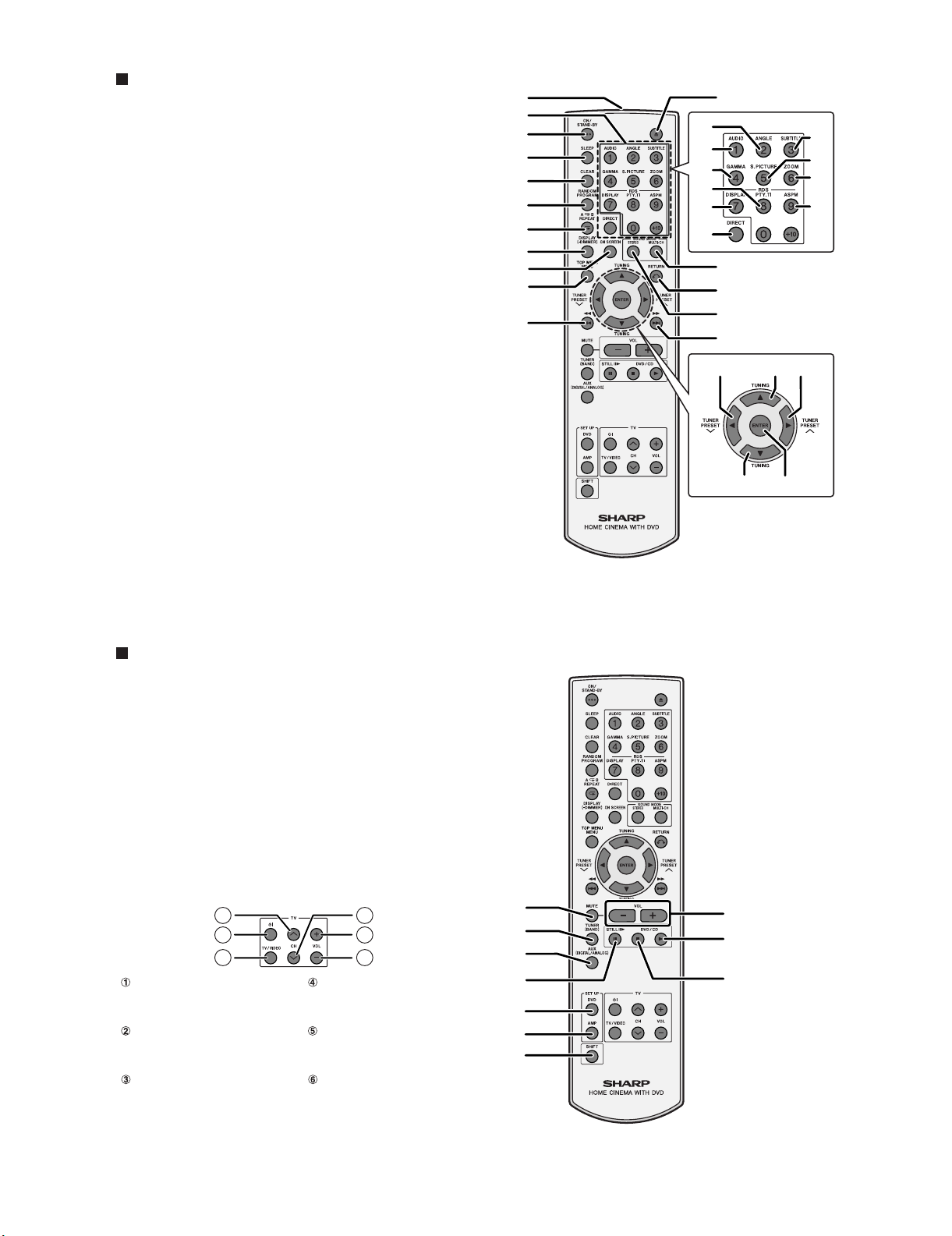
1. TUNER TEST (Tuner button + Stop button + Power
button)
1.1. INITIAL SETTINGS:
VOLUME = 20
FUNCTION = FM ST 87.50MHz (P-01)
1.2. PRESET STATIONS:
P-01: FM ST 87.50 MHz
P-02: FM ST 108.00 MHz
P-03: FM ST 98.00 MHz
P-04: FM ST 90.00 MHz
P-05: FM ST 106.00 MHz
P-06: AM 522 KHz
P-07: AM 1620 KHz
P-08: AM 990 KHz
P-09: AM 603 KHz
P-10: AM 1404 Hz
P-36: FM MONO 106.00 MHz
P-37: FM MONO 90.00 MHz
P-38: FM MONO 98.00 MHz
P-39: FM MONO 108.00 MHz
P-40: FM MONO 87.50 MHz
1.3. WHEN SYSTEM ENTER TUNER TEST MODE, BELOW
FOUR BUTTONS ON MAIN UNIT WILL CHANGE TO OTHER
FUNCTIONS TEMPORARILY
“STOP” BUTTON: TUNING DOW
“PLAY” BUTTON: TUNING UP
“SKIP DOWN” BUTTON: TUNER PRESET DOWN
“SKIP UP” BUTTON: TUNER PRESET UP
2. VOLUME TEST (SKIP Down button + STOP button
+ POWER button)
2.1. INITIAL SETTINGS:
VOLUME = 23
FUNCTION = AUX DIGITAL
FM ST FREQUENCY = 87.50MHz
FM MONO FREQUENCY = 87.50MHz
AM FREQUENCY = 522KHz
VOLUME 0 >> VOLUME 1 >> VOLUME 23 >> VOLUME 40 >> VOL-
UME MAX
3. KEY TEST (SKIP Up button + PLAY button +
POWER button)
3.1. PRESS EACH BUTTON OF MAIN UNIT EXCEPT “ON/
STAND-BY” BUTTON, AND THEN PRESS “ON/STAND-BY”
BUTTON.
KEY OK: “OK” SHOWN ON VFD
KEY NG: “ERROR”SHOWN ON VFD
4. VFD TEST (“SKIP Up button” + “STOP button” +
“POWER button”)
BACK LIGHT LED = ON
USE “SKIP UP” BUTTON TO CHANGE VFD DISPLAY MODE AND
BACK LIGHT LED MODE
5. SLOT-IN MECHA TEST (“EJECT button” + “FUNC-
TION button” + “POWER button”)
VFD DISPLAY TEST CYCLE NUMBER
DISC LOAD ERROR: “EL xx” (xx MEANS TEST CYCLE NUMBER)
DISC EJECT ERROR: “EE xx” (xx MEANS TEST CYCLE NUMBER)
First, the ALL_MUTE_OFF_TEST key code is sent to AMP to start it up
with all mute controls disabled.
6. DVD RESTORE (“PLAY button” + “FUNCTION but-
ton” + “POWER button”)
DVD SETUP SETTINGS RESTORED
AMP SETUP SETTINGS RESTORED
SOUND MODE SETTINGS RESTORED
ERRASE ALL OF CONTENTS OF PROGRAM PLAYBACK LIST
SHOW DVD ROM DATA VERSION NUMBER ON BOTH VFD AND
MONITOR
7. SYSTEM RESTORE (“STOP” button + “FUNC-
TION” button + “POWER” button)
ERRASE ALL OF CONTENTS OF TUNER MEMORY
RESET TUNER PRESET FLAG
SET INITIAL VOLUME TO 20
SET INITIAL FUNCTION TO DVD/CD
SET FM ST FREQUENCY TO 87.50MHz
SET FM MONO FREQUENCY TO 87.50MHz
SET AM FREQUENCY TO 522KHz
SHOW SYSTEM SOFTWARE VERSION ON VFD

HT-X1H
3 – 1
AudioHT-X1HService ManualHT-X1HMarketE
CHAPTER 3. MECHANISM BLOCKS
[1] Caution on diassembly
Caution on Disassembly
Follow the below-mentioned notes when disassembling the unit and reassembling it, to keep it safe and ensure excellent performance:
1. Take cassette tape, and compact disc out of the unit.
2. Be sure to remove the power supply plug from the wall outlet before starting to disassemble the unit.
3. Take off nylon bands or wire holders where they need to be removed when disassembling the unit. After servicing the unit, be sure to rearrange
the leads where they were before disassembling.
(A2)x7
M3x12mm
(A4)x5
M3x6mm
(A4)x2
M2.5x10mm
(A6)x1
M2x3mm
(A1)x1
Rear Panel Front Panel
Center Panel
1 Rear Panel with 1. Terminal Cover ....... (A1) x1
2. Screw .................... (A2) x7Terminal/Tuner
4. Screw ................... (A4) x15
5. Socket ...................... (A5) x1
PWB
DSP PWB/DVD
Unit
6. Screw ...................... (A6) x3
7. Shield Box A ........... (A7) x1
8. Shield Box B ........... (A8) x1
2 1. Screw ...................... (B1) x4
4. Screw ...................... (B4) x1
6. Screw ...................... (B6) x4
5. Bracket...................... (B5) x1
2. Flat Cable ............... (B2) x2
3. Socket ..................... (B3) x2
4. Socket ..................... (C4) x3
3. Socket ..................... (A3) x7
3 Front Panel with
Display/
Headphone/
Switch/LED PWB
1. Knob ...................... (C1) x1
2. Nut .......................... (C2) x1
3. Screw ...................... (C3) x6
5. Screw ...................... (C5) x2
6. Screw ...................... (C6) x3
7. Screw ...................... (C7) x1
STEP REMOVAL PROCEDURE
HT-X1H (DVD Unit)
(A4)x4
M3x10mm
(A3)x3
Terminal PWB
Rear Panel
Tuner PWB
(A3)x3
(A8)x1
(A3)x1
(A5)x1
(A7)x1
(A6)x1
M2x3mm
(A6)x1
M2x3mm
(A4)x4
M3x10mm
Center Panel with
(B1)x4
M3x8mm
DSP PWB
DSP PWB
Pull
Pull
DVD Unit
(B3)x2
(B5)x1
(B2)x1
(B2)x1
(B4)x1
M2.5x10mm
(B6)x4
M3x8mm
Display PWB
Center Panel

HT-X1H
3 – 2
Display PWB
Headphone PWB LED PWB
(C5)x2
M2.5x8mm
(C7)x1
M3x6mm
(C3)x6
M2.5x8mm
(C4)x1 (C4)x1
(C4)x1
(C1)x1
(C2)x1
Washer
Front Panel
(C6)x3
M2.5x8mm
Switch PWB
Front Panel

HT-X1H
3 – 3
(A1)x6
M4x16mm
(A1)x3
M3x12mm
Subwoofer Box
Rear Cabinet
1 Rear Cabinet 1. Screw ...................... (A1) x9
2 1. Screw ...................... (B1) x7
.................... (B2) x1
2. Socket
3. It pulls out to the front.
3 Main PWB 1. Screw ...................... (C1) x5
2. Socket.......................... (C2) x7
4 Amp. PWB 1. Screw .................... (D1) x13
2. Bracket.......................... (D2) x2
3. Socket.......................... (D3) x1
STEP REMOVAL PROCEDURE
HT-X1H (Subwoofer Unit)
Amp. Unit
(B2)x1
Main PWB
(B1)x3
M4x16mm
(B1)x4
M4x28mm
Suboofer Box
(C2 )x1
(C2)x1
Amp. PWB
Main PWB
Power PWB
(C1)x5
M3x6mm
(C2)x1
(C2)x2
(C2)x2
(D3)x1
(D1)x3
M3x6mm
(D1)x2
M3x6mm (D1)x2
M3x6mm
Amp. PWB
Power PWB
(D1)x6
M3x6mm
(D2)x1
(D2)x1

HT-X1H
4 – 1
AudioHT-X1HService ManualHT-X1HMarketE
CHAPTER 4. DIAGRAMS
[1] Block diagram
Q103
CNP402B
CNP402A
D102
Q102
Q101
F102
ZD102 ZD101
IC104
NJM4558D
F101
CNP202
D101
CNS402A FROM
POWER1 PWB
CNS402B
FROM
POWER1 PWB
FROM
MAIN POWER TRANSFORMER
CNS202
C/SW
IC101
POWER AMP.
LM4732TA
34
5
6
7
12
8
IC104
BUFFER
AMP.
Figure 4-1 BLOCK DIAGRAM (1/8)

HT-X1H
4 – 2
CNP401
F101
R
MER
IC103
POWER AMP.
LM4732TA
CNS401
FROM
POWER1 PWB
FL/FR
IC102
POWER AMP.
LM4732TA
SL/SR
Figure 4-2 BLOCK DIAGRAM (2/8)

HT-X1H
4 – 3
RLY402
RLY401
D432
D435
Q447
Q443
D459
D458
D457
D456
D442
D443
D440
D441
D455
D454
D453
D452
BI402
CNP402
TO
AMP.PWB
BI401
2345678910
1
Q455
Q450
Q451
Q452
ZD424
Q453
Q459
Q457
Q454
Q456
D434
Q448
D433
Q446
S102B
13
12
11
10
9
8
7
6
5
4
3
2
1
Q458
IC407
TCD4094B
D216
IC203
AN78L
0
VOLTAGE RE
G
3
2
1
3
2
IC406
NJM4558D
Q412
IC405
NJM4558D
IC404 IC404
BUFFER
IC405
BUFFER
IC406
BUFFER
NJM4558D
Q403
Q407
Q404
Q408
Q409
D426
D425
Q414
D410
Q413
Q434
Q435
ZD423
Q429
D42
2
S101B
S101A
TO
MAIN PWB
13
12
11
10
9
8
7
6
5
4
3
2
1
3
1
2
4 3 2 1
5 6 7 8
4 3 2 1
5 6 7 8
4 3 2 1
5 6 7 8
1716151413 12 1110
1 2 3 4 5 6 7 8
IC2
0
S101A
TO
MAIN PWB
CNP401
TO
AMP.PWB
Figure 4-3 BLOCK DIAGRAM (3/8)

HT-X1H
4 – 4
-
-
-
-
+
+
+
+
-
+
AC SOCKET
+
-
+
+
+
+
-
-
-
-
RLY402
RLY401
D432
D435
Q447
Q443
ZD425
D431
Q445
Q444 D429
BI401
2345678910
1
L415
D437
D436
D221
D434
Q448
D433
Q446
T201
POWER TRANSFORMER
CNP203
BI203
CNP201
CNS201
CNP205
3
2
1
D427A
M
M402
M
M401
BI205
3
2
1
Q439A
Q438A
Q437A
Q436A
Q433
Q432
Q437
D427
Q438
Q439
Q436
L410
L414
L413
L412
L411
D216
IC203
AN78L05
VOLTAGE REGULATOR
3
2
1
T202
SUB POWER
TRANSFORMER
D209
LF201
LINE FILTER
S0202
RLY400
Q203
D218
D219 D220
D217
ZD201
CNP204
CNS202
TO
AMP PWB
CNS204
IC201
KIA7805API
VOLTAGE
REGULATOR
3
2
1
IC202
KIA7812API
VOLTAGE
REGULATOR
3
2
1
ZD202
D210
D211
Q201
D208
D207
D205
F201
D206
D212
D411
Q416
Q415
SO401
CNP206
D426
D425
D424
1N4004
RLY403
Q413
Q434
Q435
ZD423
D416
D419
D420
D417
D418
D421
Q430
Q429
D422
2
1
3
2
1
3
IC201
CNS202
AC POWER
SUPPLY CORD
AC 230 V,
50 Hz
CNP401
TO
AMP.PWB
Figure 4-4 BLOCK DIAGRAM (4/8)

HT-X1H
4 – 5
CFW9
SW700
JOG VOLUME
D706B
D706A
D707 1N4148
CNW702
TO
MAIN PWB
BI301
CNW704
LED702 LPBB73V1
CNW707 CNP707
Q702
Q701
X701
D708
L704
D706
CNW703
L702
X702
IC701
0058SJ
SYSTEM MICROCOMPUT
E
D701
TO
MAIN PWB
TO
DVD SERVO
PWB
TO
TUNER PWB
Figure 4-5 BLOCK DIAGRAM (5/8)

HT-X1H
4 – 6
CFW6
CFW9
6
B
CNP706
FROM
DVD MECHIANISM
CNP705
CNW705
L706
L701
RX701
GP1UD261
321
CNP609
CNW609
RX702
GP1UD261
3
21
Q506
Q510
Q507
Q509
Q505 Q508
VFD701
FL DISPLAY
Q704
D702
D703
L705
L703
O
MPUTER
ZD701
D704
Q703
Q709
D705
SW701
SW708
SW704 SW707
SW706
SW705
SW703
SW702
Figure 4-6 BLOCK DIAGRAM (6/8)

HT-X1H
4 – 7
NC
CL
VDD
VREF
ROUT
RBS
RTRE
RIN
RSL0
R4
R3
R2
R1 L1
L2
L3
L4
LSL0
LIN
LTRE
LOUT
VSS
CE
DI
LBS
AUX L
D509
CNW302
FROM
TUNER PWB
Q501
S101A
TO
POWER1 PWB
13
12
11
10
9
8
7
6
5
4
3
2
1
IC501
KIA7812API
3
3
2
2
1
1
Q502
D508
IC504
NJM4558D
IC512
NJM4558D
IC507
CD4053M
IC505
LC75341M
TO
DVD SERVO PWB
BI501
IC503
LM2576T
D505
IC502
KIA7805API
D506
D507
L501
S102A
13
12
11
10
9
8
7
6
5
4
3
2
1
L502
CNW508A CNW508B
CNP702
FROM
DISPLAY PWB
TO
POWER1 PWB
IC509
NJM14558
IC508
NJM14558
IC406
NJM14558
Figure 4-7 BLOCK DIAGRAM (7/8)

HT-X1H
4 – 8
1
2
DI
CL
TUN L
TUN R
CE
L513A
L513B
CFW5
D512
D511
9
L5A1
D503
D504
BI503
TO
DVD SERVO PWB
10
9
8
7
6
5
4
3
2
1
Q5A3
Q5A4
IC511
KIA7805API
1
2
3
Q503
BI506
S505
SCART
BI502
S501
L506
L507
L511
L512
L510
L509
L503
S503
32 1
CNP704
FROM
DISPLAY PWB
FROM
DVD SERVO PWB
Q518
Q517
IC510
NJM4558D
S504
L508
Q504
Q522
Q521
Q523
TO
DVD SERVO PWB
Figure 4-8 BLOCK DIAGRAM (8/8)

HT-X1H
5 – 1
AudioHT-X1HService ManualHT-X1HMarketE
CHAPTER 5. CIRCUIT DESCRIPTION
[1] Notes on schematic diagram
•Resistor:
To differentiate the units of resistors, such symbol as K and M are
used: the symbol K means 1000 ohm and the symbol M means
1000 kohm and the resistor without any symbol is ohm-type resis-
tor. Besides, the one with “Fusible” is a fuse type.
• Capacitor:
To indicate the unit of capacitor, a symbol P is used: this symbol P
means pico-farad and the unit of the capacitor without such a sym-
bol is microfarad. As to electrolytic capacitor, the expression
“capacitance/withstand voltage” is used.
(CH), (TH), (RH), (UJ): Temperature compensation
(ML): Mylar type
(P.P.): Polypropylene type
• Schematic diagram and Wiring Side of P.W.Board for this model are
subject to change for improvement without prior notice.
• The indicated voltage in each section is the one measured by Digi-
tal Multimeter between such a section and the chassis with no sig-
nal given.
1. In the tuner section,
indicates AM
indicates FM stereo
2. In the CD section, the CD is stopped.
• Parts marked with “ “ ( ) are important for main-
taining the safety of the set. Be sure to replace these parts with
[2] Types of transistor
2SD601 AR
B
(3)
E
(1)
C
(2)
TOP
VIEW
2HC1815 GR
2SC535 C
2SC380 O
KRC104 M
KTA1266 GR
KTA1271 Y
KRA107 M
VIEW
FRONT
ECB
(S)(G)(D)
(1)(2)(3)
KRC107 M
KTC3199 GR
KTC3200 GR
KTC3203 Y
2SB562 C
Other manuals for HT-X1H
1
Table of contents
Other Sharp Home Theater System manuals

Sharp
Sharp HT-CN400DVH User manual

Sharp
Sharp HT-CN400DVW User manual

Sharp
Sharp HT-X1 User manual

Sharp
Sharp HT-CN400DVH User manual

Sharp
Sharp SD-PX15H User manual

Sharp
Sharp HT-SB20 User manual

Sharp
Sharp HT-M750H User manual

Sharp
Sharp SD-AS10 User manual

Sharp
Sharp HT-SL70 User manual

Sharp
Sharp HT-SL72 User manual

Sharp
Sharp HT-SBW182 User manual

Sharp
Sharp HT-DP2500W User manual

Sharp
Sharp SBW800 User manual

Sharp
Sharp CD-DVD500 User manual

Sharp
Sharp HT-SB60 User manual

Sharp
Sharp HT-X1H User manual

Sharp
Sharp Aquos AN-ACS1U User manual

Sharp
Sharp HT-SB20 User manual

Sharp
Sharp HT-SB60 User manual

Sharp
Sharp SD-AT100W User manual