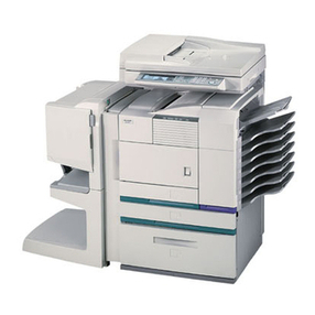
Sharp AR-MS1 User manual

This document has been published to be used for
after sales service only.
The contents are subject to change without notice.
Parts marked with “ “ are important for maintaining the safety of the set.
Be sure to replace these parts with specified ones for maintaining the safety and performance of the set.
SHARP CORPORATION
LASERPRINTEROPTIONS
MAILBINSTACKER
MODEL AR-MS1
CODE : 00ZARMS1//A1E
[1] PRODUCT OUTLINE . . . . . . . . . . . . . . . . . . . . . . . . . . . . . . . . 1 - 1
[2] CONFIGURATION . . . . . . . . . . . . . . . . . . . . . . . . . . . . . . . . . . 2 - 1
[3] SPECIFICATIONS . . . . . . . . . . . . . . . . . . . . . . . . . . . . . . . . . . 3 - 1
[4] UNPACKING AND INSTALLATION. . . . . . . . . . . . . . . . . . . . . . 4 - 1
[5] EXTERNAL VIEWS AND INTERNAL STRUCTURES. . . . . . . 5 - 1
[6] MACHINE OPERATION . . . . . . . . . . . . . . . . . . . . . . . . . . . . . . 6 - 1
[7] DISASSEMBLY AND ASSEMBLY, MAINTENANCE. . . . . . . . . 7 - 1
[8] ELECTRICAL SECTION . . . . . . . . . . . . . . . . . . . . . . . . . . . . . 8 - 1
CONTENTS
AR-MS1

AR-MS1 PRODUCT OUTLINE, CONFIGURATION 1-1
[1] PRODUCT OUTLINE
This unit is a paper exit unit, which allows to select a desirable tray in two or more paper exit trays (male bins), when installed to the following machines.
[2] CONFIGURATION
1. Before installation of this unit, one of the multi-purpose tray (AR-MU1), the large capacity paper feed desk (AR-D13), and the 3-stage paper feed
desk (AR-D14) must be installed.
2. When installing this unit together with the AR-MJ1, it may be required to install the optional power unit (AR-DC1) together.
3. This unit cannot be installed together with the finisher (AR-FN6) or the paper exit extension tray (AR-TE4) .
Applicable models AR-P350 / P450, AR-M350 / M450
Output units
AR-MS1
Scanner rack
Mail-bin stacker
=Any of the units must be installed together.
Multi purpose drawer
Stand/3 x 500 sheet paper drawer
Stand/MPD & 2000 sheet
Duplex module/bypass tray
Duplex module
B/W scanner module/DSPF
Saddle stitch finisher
Finisher
Mail-bin stacker
Exit tray
Punch unit
PS3 expansion kit
Facsimile expansion kit
Print server card
Hard disk drive
Power supply unit
Upper exit tray extension
Multi-function controller board
Fax memory (8 MB)
Network scanner expansion kit
*1
*1
B/W scanner module/DSPF(AR-EF1)
Upper exit tray
extension
(AR-TE4)
Finisher
(AR-FN6)
Mail-bin stacker
(AR-MS1)
Stand/MPD & 2000 sheet
paper drawer
(AR-D13)
Power supply unit
(AR-DC1)
Multi purpose drawer
(AR-MU1)
Stand/3 x 500 sheet
paper drawer
(AR-D14)
Saddle stitch
finisher
(AR-FN7)
Duplex
module/bypass tray
(AR-DU4)
Exit tray
(AR-TE3 or AR-DU4 Standard)
Duplex module
(AR-DU3)
Simultaneous installation not allowed
Simultaneous installation is required
! "#$%&'

AR-MS1 SPECIFICATIONS 3-1
[3] SPECIFICATIONS
1. Basic
Type Desktop type mail bin stacker with 8-exit-tray
Transport speed To support 35-45 sheet/minute
Transport alignment Center alignment
Tray type
(No. of tray) Upper
tray EXIT tray
Lower
Tray Mail bin tray (7 stages)
Output paper
capacity Upper
tray 250 sheets (A4/8.5"x11", 80g/m²)
Lower
Tray 100 sheets/bin (A4/8.5"x11", 80g/m²)
Output paper delivery Face-down
Output paper
size Upper
tray A3, B4, A4, A4R, B5, B5R, A5R
11"x17", 8.5"x14", 8.5"x13", 8.5"x11",
8.5"x11"R,5.5"x8.5"R,
Executive, Japanese post card,
Monarch(98x191),Com-10(105x241),
DL(110x220),C5(162x229),
ISO B5(176x250)
Lower
Tray A3, B4, A4, A4R, B5, B5R
11"x17", 8.5"x14", 8.5"x13",
8.5"x11", 8.5"x11"R,
Executive
Specofmedia
for paper
output
Upper
tray Tracing paper:52-59g/m² / 14-15lbs
Plain paper:60-128g/m² / 16-34lbs
Index paper:176g/m² / 47lbs
Cover paper:205g/m² / 54-55lbs
Transparency
Lower
Tray Plain 60-105g/m² / 16-28lbs
Remaining
paper
detection
Upper
tray Not Provided
Lower
Tray Not Provided
Exit tray full
detection Upper
tray Provided
Lower
tray Provided
Power consumption Less than about 20.2W
Power source Supplied from the optional power source
(DC24V 0.8A / DC5V 0.2A)
External
dimensions(WxDxH) 465x530x508 (mm)
Occupied
dimensions(WxD) 465x530 (mm)
Weight Approx. 19kg
!"#$%&

AR-MS1 UNPACKING AND INSTALLATION 4-1
[4] UNPACKING AND INSTALLATION
<Before installation>
•Start installation after checking that the DATA and COMMUNICATION
indicators on the operation panel are neither lit nor blinking.
•For installation of AR-MS1, an optional stand/paper drawer (stand/MPD
& 2000 sheet paper drawer, stand/3 x 500 sheet paper drawer or multi
purpose drawer) must have been installed.
Also if a multi purpose drawer has been installed, a power supply unit
(AR-DC1) is needed additionally.
1) Turn off the main switch of the main unit of the printer.
Turn the main switch located on the front side of the main unit to the
"OFF" position.
Then, remove the power plug of the main unit from the outlet.
2) Remove the upper cabinet of the stand/paper drawer.
<1>Pull out the paper tray of the stand/paper drawer.
Remove the four screws of the cabinet attached to the right side of
the main unit of the printer and remove the cabinet.
<2>Mount screw B to the position shown in the illustration.
3) Attach the mail-bin stacker.
<1>Remove the paper exit actuator from the main unit of the printer.
<2>Raise the relay unit at the side of the mail-bin stacker.
Caution: Do not press on the relay unit while it is raised.
(Doing so may deform or damage the unit.)
<3>Hold the grip of the mail-bin stacker and place the mail-bin stacker
on the stand/paper drawer temporarily.
<4>push the lower part to attach the mail-bin stacker by sliding it toward
the exit tray of the main unit. At this time, align the mail-bin stacker
with the exterior line of the stand/paper drawer.
<Parts included>
Mounting plates: 2 pcs.
Tray: 1 pc.
Screw B: 1 pc.
Screws A (M4x8): 5 pcs.
"OFF"
Cabinet
Screw B
Actuator
Relay unit
Push.
Push.
Place.
Grip
Grip
"# $%&'()

AR-MS1 UNPACKING AND INSTALLATION 4-2
<5>Open the front cover of the mail-bin stacker and fix the stacker with
three screws A at the positions shown in the illustration.
<6>Then, close the front cover and close the paper tray of the stand/
paper drawer.
<7>Attach the mounting plates to the positions shown in the illustration
and fix them with screws A.
Caution: Insert the mounting plate under the desk frame.
4) Attach the tray.
Steps 5) and after are the procedure to be carried out when a multi
purpose drawer has been installed.
If a stand/MPD & 2000 sheet paper drawer or a stand/3 x 500 sheet
paper drawer has been installed, carry out steps 8) and after.
5) Process the AC inlet cover attached to the rear cabinet of the stand/
paper drawer.
<1>Remove the two screws that secure the rear cabinet and remove the
rear cabinet.
<2> Remove the screw that fixes the AC inlet cover and then remove the
AC inlet cover.
Process the AC inlet cover as shown in the illustration.
6) Attach the power supply unit.
Attach the power supply unit to the hanging portions and secure it
using the supplied three screws.
7) Connect the power supply unit harness to the PCU PWB of the main
unit of the printer.
<1>Connect the power supply unit harness to the PCU PWB of the main
unit of the printer.
Screw A
Screw A
(Front side)
Mounting plate
Screws A
(Rear side)
Desk frame
Mounting plate
Tray
Cut out.
AC inlet cover
Screw
Screw
Screw
Rear
cabinet
Optional power supply unit
Screws
Screw
Hanging portion
Hanging portion
Harness cover
Screw
* "# $%&'()

AR-MS1 UNPACKING AND INSTALLATION 4-3
<2>Connect the power supply unit harness connector to CN11
(red connector) of the PCU PWB of the main unit of the printer.
<3>Reattach the harness cover to its original position and fix it with the
removed screw.
At this time, ensure that the power supply unit harness is arranged
as shown in the illustration.
* Fix the harness securely to the wire saddle.
8) Remove the AC inlet cover and then remove the rear cabinet of the
stand/paper drawer.
<1>Remove the screw that fixes the AC inlet cover and then remove the
AC inlet cover.
<2>Remove the AC cord of the power supply unit from the inlet
connector of the main unit of the printer.
Remove the four screws thatfix the rear cabinet andthen remove the
rear cabinet.
9) Arrange the harness of the mail-bin stacker.
<1>Pass the harness of the mail-bin stacker between the power supply
unit and the frame of the stand/paper drawer and connect it to the
connector of the power supply unit.
<2>Fit the snap band attached to the mail-bin stacker at the position
shown in the illustration to fix the harness.
10) Attach the rear cabinet of the stand/paper drawer.
<1>Pass the AC cord of the power supply unit as shown in the illustration
and fix the rear cabinet of the stand/paper drawer with the screws.
<2>Attach the AC inlet cover to the rear cabinet of the stand/paper
drawer and fix it with the removed screw.
11) Connect the AC cord of the optional power supply unit to the main
unit of the printer.
<1>Connect the AC cord of the power supply unit to the inlet connector
of the main unit of the printer at the location shown in the illustration.
Connector
CN11
Wire saddle
Harness cover
Optional power
supply harnesses
Screw
Wire saddle
Screw
AC inlet cover
(* Similar work for the multi purpose drawer)
Rear cabinet
(* Similar work for the multi purpose drawer)
Power supply
unit connecto
r
Snap band
Mail-bin stacker harness
(* Similar work for the multi purpose drawer)
Rear cabinet
(* Similar work for the multi purpose drawer)
Screw
AC inlet cover
(* Similar work for the multi purpose drawer)
AC cord
(* Similar work for the multi purpose drawer)
+ "# $%&'()

AR-MS1 EXTERNAL VIEWS AND INTERNAL STRUCTURES 5-1
[5] EXTERNAL VIEWS AND INTERNAL STRUCTURES
A. External view
B. Internal structure
1 Top cover 2 Top stage tray 3 Male bin tray
4 Front cover
1 Paper entry sensor (PID) 15 29 Paper transport roller 7
2 Transport sensor (MPPD1) 16 Switchback (paper entry) gate 30 Male bin tray 6 paper exit roller
3 Transport sensor (MPPD2) 17 Paper transport roller 1 31 Male bin tray 7 paper exit roller
4 Transport sensor (MPPD3) 18 Paper transport roller 2 32 Tray select gate 6
5 Transport sensor (MPPD4) 19 Paper transport roller 3 33 Tray select gate 5
6 Transport sensor (MPPD5) 20 Upper stage tray paper exit roller 34 Tray select gate 4
7 Paper exit full detection 1 (MPFD1) 21 Paper transport roller 4 35 Tray select gate 3
8 Paper exit full detection 2 (MPFD2) 22 Male bin tray 1 paper exit roller 36 Tray select gate 2
9 Paper exit full detection 3 (MPFD3) 23 Paper transport roller 5 37 Tray select gate 1
10 Paper exit full detection 4 (MPFD4) 24 Male bin tray 2 paper exit roller 38 Upper stage tray select gate
11 Paper exit full detection 5 (MPFD5) 25 Male bin tray 3 paper exit roller
12 Paper exit full detection 6 (MPFD6) 26 Paper transport roller 6
13 Paper exit full detection 7 (MPFD7) 27 Male bin tray 4 paper exit roller
14 Paper exit full detection 8 (MPFD8) 28 Male bin tray 5 paper exit roller
12
4
3
1.PID
16 17 18 19 20
21
22 23
2.MPPD1
3.MPPD2
4.MPPD3
5.MPPD4
6.MPPD5
7.MPFD1
8.MPFD2
9.MPFD3
10.MPFD4
11.MPFD5
12.MPFD6
13.MPFD7
14.MPFD8
16.MDD1
24
25
27
28
30
31
32
33
34
35
36
37
38
29
26
! "#$%&

AR-MS1 EXTERNAL VIEWS AND INTERNAL STRUCTURES 5-2
C. Sensor
Code Name Function Active condition Remark
1 PID Paper entry sensor Detection of paper entry
into the interface transport section L: Paper loaded
(sensor ON)
2 MPPD1 Transport sensor 1 Paper transport detection L: Paper loaded
(sensor ON)
3 MPPD2 Transport sensor 2 Paper transport detection L: Paper loaded
(sensor ON)
4 MPPD3 Transport sensor 3 Paper transport detection L: Paper loaded
5 MPPD4 Transport sensor 4 Paper transport detection L: Paper loaded
6 MPPD5 Transport sensor 5 Paper transport detection L: Paper loaded
7 MPFD1 Paper exit full sensor 1 Top tray full detection L: Paper full detected
8 MPFD2 Paper exit full sensor 2 No. 1 bin tray full detection H: Paper full detected
9 MPFD3 Paper exit full sensor 3 No. 2 bin tray full detection H: Paper full detected
10 MPFD4 Paper exit full sensor 4 No. 3 bin tray full detection H: Paper full detected
11 MPFD5 Paper exit full sensor 5 No. 4 bin tray full detection H: Paper full detected
12 MPFD6 Paper exit full sensor 6 No. 5 bin tray full detection H: Paper full detected
13 MPFD7 Paper exit full sensor 7 No. 6 bin tray full detection H: Paper full detected
14 MPFD8 Paper exit full sensor 8 No. 7 bin tray full detection H: Paper full detected
15 DOPD Top cover open/close sensor Top cover open/close detection L: Upper cover open
16 MDD1 Front cover open/close sensor Front cover open/close detection L: Front cover open
15.DOPD
1.PID
2.MPPD1
3.MPPD2
4.MPPD3
5.MPPD4
16.MDD1
6.MPPD5
8.MPFD2
7.MPFD1
9.MPFD3
10.MPFD4
11.MPFD5
12.MPFD6
13.MPFD7
14.MPFD8
' ! "#$%&

AR-MS1 EXTERNAL VIEWS AND INTERNAL STRUCTURES 5-3
D. Motor, clutch, PWB
Code Name Function Remark
1 SM MAIN PWB Male bin control PWB Communication with the machine, operation
and control of the machine
2 MM Transport motor Drives rollers.
3 GSOL1 No. 1 gate solenoid No. 1 gate select
4 GSOL2 No. 2 gate solenoid No. 2 gate select
5 GSOL3 No. 3 gate solenoid No. 3 gate select
6 GSOL4 No. 4 gate solenoid No. 4 gate select
7 GSOL5 No. 5 gate solenoid No. 5 gate select
8 GSOL6 No. 6 gate solenoid No. 6 gate select
9 GSOL7 No. 7 gate solenoid No. 7 gate select
10 FGS Paper entry gate solenoid Paper entry gate select
1.SM MAIN PWB
2.MM
3.GSOL1
10.FGS
4.GSOL2
5.GSOL3
6.GSOL4
7.GSOL5
8.GSOL6
9.GSOL7
( ! "#$%&

AR-MS1 MACHINE OPERATION 6-1
[6] MACHINE OPERATION
1. Setting in the printer driver
When printing, to specify a mail bin, select "Properties" in the printer driver setting screen and set as follows.
A. Specifying a mail bin
Open the "Paper" tab and select a mail bin for delivery in the "Output" drop down. (The top tray can be selected.)
Note:
•The settings screens above will appear only if the devices have been set properly in the printer driver configuration.
•The combination of paper selection and other functions may not be compatible. For instance, if heavy paper, envelopes, label stock, etc. are selected,
it will not be possible to select duplex, offset tray, saddle stitch, etc. For details, see printer driver help.
The illustration below shows the screen for a PCL printer driver in the Windows 98 environment.
! "#$%&

AR-MS1 DISASSEMBLY AND ASSEMBLY, MAINTENANCE 7-1
[7] DISASSEMBLY AND ASSEMBLY, MAINTENANCE
1.Maintenance System Table
Check (Clean, replace, or adjust as necessary.) Clean Replace Adjust Lubricate Move position
Unit name Part name When
calling 50K 100K 150K 200K 250K 300K 350K 400K Remark
Transport section Transport rollers
Transport paper guides
Drive section Gears (Specified position)
Belts
Other Sensors
Discharge brushes
! "#$%&

AR-MS1 DISASSEMBLY AND ASSEMBLY, MAINTENANCE 7-2
2. Disassembly and assembly
A. Unit transit
Note: When carrying the Mail bin stacker unit removed from the printer,
fold the transport unit as described below.
If not, the frame may be bent, causing a breakdown of the
machine.
B. External cabinet
C. Transport unit
(1) Gate solenoid
(2) Transport roller
1)
2)
1)
2)
2)
3)
4)
4)
5)
6) 5)
7)
8)
No. Parts name Job item cycle
1 Transport rollers Clean 100K
2 Transport paper guide Clean 100K
3 Gears Lubricate 100K
4 Belts Check 300K
2)
2)
3)
4)
1)
1)
2)
1)
2)
3)
4)
5)
4)
' ! "#$%&

AR-MS1 DISASSEMBLY AND ASSEMBLY, MAINTENANCE 7-3
(3) Upper open/close sensor
(4) Upper cover
(5) Paper entry sensor
(6) Transport roller
1)
2)
3)
4) 5)
6)
3)
2)
1)
1)
3)
4)
1)
2)
3)
5)
4) 6) 7)
8)
9) 10) 11)
5)
4)
3)
4) 3)
2) 1)
3)
2)
1)
1)
2)
3)
1)
1)
1)
4)
5)
3)
2)
( ! "#$%&

AR-MS1 DISASSEMBLY AND ASSEMBLY, MAINTENANCE 7-4
D. Inside of the unit
(1)Transport sensor
(2)Transport sensor
(3)Paper guide
* When assembling the paper guide, check to insure that the paper
guide boss is securely inserted into the mounting hole.
No. Parts name Job item cycle
1 Sensors Clean 100K
2 Transport paper guides Clean 100K
1)
2)
1)
1)
2)
2)
3)
1)
2)
3)
4)
3)
5) 6) 5)
1)
1)
2)
2)
3)
3)
4)
5)
5)
4)
1)
2)
3)
4)
5)
1)
2)
3)
4)
6)
1)
2)
1)
3) 6)
4)
5)
) ! "#$%&

AR-MS1 DISASSEMBLY AND ASSEMBLY, MAINTENANCE 7-5
E. Front side of the unit
(1)Front door open/close sensor
F. Rear side of the unit
(1)Main PWB/Main motor
(2)Paper exit full sensor
No. Parts name Job item cycle
1 Sensors Clean 100K
1)
2)
2)
3)
1)
2)
No. Parts name Job item cycle
1 Sensors Clean 100K
1)
2)
1)
1)
1)
2)
3)
1)
2)
2)
2)
1)
2)
3) 4)
* ! "#$%&

AR-MS1 DISASSEMBLY AND ASSEMBLY, MAINTENANCE 7-6
G. Upper side of the unit
(1)Paper guide
(2)Paper transport sensor/Paper exit full sensor
(3)Gate solenoid
(4)Transport roller
H. Right side of the unit (Paper exit side)
No. Parts name Job item cycle
1 Sensors Check 100K
2 Discharge brushes Lubricate 100K
3 Transport rollers Clean 100K
1)
2)
2)
3)
1)
2)
1)
1)
1)
2)
3) 2)
No. Parts name Job item cycle
1 Sensors Check 100K
2 Discharge brushes Lubricate 100K
3 Transport rollers Clean 100K
3)
1)
2)
1)
1)
2)
2)
2)
2)
3)
4)
5)
3) 4)
5) 3)
4)
5)
6)
7)
6)
8)
1)
2)
3)
3)
4)
+ ! "#$%&

AR-MS1 DISASSEMBLY AND ASSEMBLY, MAINTENANCE 7-7
(1)Paper transport sensor
I . Paper exit tray unit
(1)Gate tray
(2) Paper exit full sensor
No. Parts name Job item cycle
1 Sensors Clean 100K
2 Transport paper guides Clean 100K
1)
1)
2)
3)
2)3)
3) 4)
5)
1)
4)
7)
10)
13)
16)
19)
2)
2)
5)
11)
14)
17)
20)
22)
3)
9)
5)
11)
14)
17)
20)
22)
12)
15)
18)
21)
23)
1)
1) 1) 2)
1)
2)
3)
4)
! "#$%&

AR-MS1 ELECTRICAL SECTION 8-1
[8] ELECTRICAL SECTION
1. BLOCK DIAGRAM
CPU
XTAL
4.91MHz
DRIVER
IC
GSOL1
GSOL2
GSOL3
GSOL4
GSOL5
GSOL6
GSOL7
MM
IMPORT
CIRCUIT
EXPORT
CIRCUIT
IMPORT
CIRCUIT
EXPORT
CIRCUIT
MPPD1
MPPD2
MPPD3
MPPD4
MPPD5
MPFD1
MPFD2
MPFD3
MPFD4
MPFD5
MPFD6
MPFD7
MPFD8
IMPORT
CIRCUIT
IMPORT
CIRCUIT
IMPORT
CIRCUIT
IMPORT
CIRCUIT
IMPORT
CIRCUIT
IMPORT
CIRCUIT
IMPORT
CIRCUIT
IMPORT
CIRCUIT
IMPORT
CIRCUIT
IMPORT
CIRCUIT
IMPORT
CIRCUIT
IMPORT
CIRCUIT
IMPORT
CIRCUIT
IMPORT
CIRCUIT
IMPORT
CIRCUIT
EXPORT
CIRCUIT
CURRENNT LIMIT
CURRENNT LIMIT
DOPD
RELAY UN
PID
FGS
CURRENNT LIMIT
MDD1
IMPORT
CIRCUIT
IMPORT
CIRCUIT
IMPORT
CIRCUIT
IMPORT
CIRCUIT
POWER UN
SMALL
MAIL BIN
UN
SMALL MAIL BIN PWB
ROM
+24V
+24V
+5V
+5V
+24V
+5V
+24V
+5V
A
A
B
B
C
C
D
D
E
E
4 4
3 3
2 2
1 1
MAIL-BIN STACKER BLOCK DIAGRAM
!"#$%

AR-MS1 ELECTRICAL SECTION 8-2
2. WIRING DIAGRAM
A
A
B
B
C
C
D
D
E
E
4 4
3 3
2 2
1 1
MAIL-BIN STACKER WIRING DIAGRAM
5
2
1 +24V
GND1
MME/
MMLK/
MMCK MM
MDD1
2
1+24V
+24VM DOOR SW
MAIN MOTOR
SMP-9V-BC SMR-9V-B
OPDCPS
SM MAIN PWB
UNIT OUTSIDE
1COM(MPPD2) MPPD2
MPPD2
2GND2
3
1+5V MPPD3
MPPD3
2GND2
3
1+5V MPPD4
MPPD4
2GND2
3
GND2
1MPPD5 MPPD5
2
3
+5V
10
9
1
5
6
2
7
3
8
4
11
12
SMP-18V-NC SMR-18V-N
1 COM(PID)
GND2 PID
2
3 PID
2GND2 DOPD
+5V1
3DOPD
PAPER IN SENSOR
DOOR OPEN SENSOR
1
2
3
4
5
6
7
8
9
RERAY PASS UN
GSOL2 2
1
MPFD2
GND2
MPFD2 1+5V 2
3
1
2
GSOL3
1+5V 2
3
MPFD3
MPFD3 GND2
1
GND2
MPFD4 MPFD4 3
2
+5V 1
GSOL4 2
2
1+5V
GND2 3
MPFD5 MPFD5
1
MPFD6
MPFD6 3
2
2
1
GND2
+5V
GSOL6
2
1+24V
GND1
25COM(PID)
(B32B-PHDSS) CN-D
CN-A (B16B-PHDSS)
1FGS
2RERAY PASS UN GATE SOLENOID
1
2
3
4
5
6
7
8
9
SMP-12V-BCSMR-12V-B
14
13
15
16
18
17
3
4
6
5
7
8
10
9
11
12
14
13
15
16
+24V
GND1
+24V
GND1
GND2
GND2
+5V
N.C
TXD-FIN2
RXD-FIN2
DTR-FIN2/
DSR-FIN2/
RES-FIN2
FGS-FIN2
GND2 3
MPFD1
1
3
GATE SOLENOID 1
1
3
2
1
MPPD1
PAPER FULL SENSOR 1
GSOL1
2
MPPD1 COM(MPPD1)
GND2
PAPER PASS SENSOR 1 2
MPFD1
1
2
+5V
GSOL5 1
2
3
1
+5V
MPFD7
1
+5V
MPFD7
MPFD8
1
2
GND2
MPFD8
3
2
GND2
GSOL7 2
16
+24V
+24V
+5V
3
11
MPFD5
7
+24V
5
18
+5V
CN-C (B18B-PHDSS)
GND2
13
2
1
N.C
10
+5V
9
GND2
14
GSOL3
GSOL2
MPFD3
15
4
12
GND2
8
GSOL4
6
17
MPFD4
N.C
N.C
MPFD7
3
11
+5V
8
+24V
+5V
GND2
+24V
MPFD6
GND2
CN-B (B18B-PHDSS)
12
9
2
5
6
13
15
N.C
+5V
+24V
GSOL6
1
18
4
14
7
GND2
10
MPFD8
17
GSOL5
16
N.C
N.C
GSOL7
GND2
23
15
19
16 +5V
COM(MPPD1)
24 +24V
22
MPFD2
18
21
GND2
MPFD1
GND2
GSOL1
14
13
CN-D (B32B-PHDSS)
+5V20 MPPD1
10
11
12
27
29
26
28
30
31
32
GND2
PID
+5V
DOPD
GND2
+24V
FGS
5+24VM
(B9B-PH-K-S) CN-E
8
7
9
GND1
MME/
MMLK/
MMCK
3
1
COM(MPPD2)
GND2
CN-D (B12B-PHDSS)
5
2
6
4
7
9
8
11
10
12
MPPD2
+5V
GND2
MPPD3
+5V
GND2
MPPD4
+5V
GND2
MPPD5
P-GND
16
RXD-FIN2/
RES-FIN2
13
P-GND
2
6
GND2
15
DSR-FIN2/
S-GND
N.C.
FGS-FIN/
9
17
14
S-GND
7
4
+24V-F
TXD-FIN2
+5V
DTR-FIN2/
1
SMR-18V-N
12
5
18
P-GND
+24V-F
10
3
11
F.G.
+24V-F
8
3
4
+24V
6
PAPER FULL SENSOR 2
GATE SOLENOID 2
PAPER FULL SENSOR 3
GATE SOLENOID 3
PAPER FULL SENSOR 4
GATE SOLENOID 4
PAPER FULL SENSOR 5
PAPER FULL SENSOR 6
GATE SOLENOID 5
GATE SOLENOID 6
PAPER FULL SENSOR 7
GATE SOLENOID 7
PAPER FULL SENSOR 8
PAPER PASS SENSOR 2
PAPER PASS SENSOR 3
PAPER PASS SENSOR 4
PAPER PASS SENSOR 5
4
5
6
1
2
3
4
N.C
N.C
+24VM
(B2B-PH-K-S) CN-F
+24V
FAN 2
1
Transport UN
& !"#$%

AR-MS1 ELECTRICAL SECTION 8-3
3. CIRCUIT DIAGRAM
POWER
(JST:B16B-PHDSS-B)
7
POWER
FGS-FIN/
GND2 6
N.C
14
TXD-FIN2
RES-FIN2 15
5+24V
RXD-FIN2
4
FGS
12
DTR-FIN2/
+24V 3
GND2
11 DSR-FIN2/
16
2
10
GND1
UART
1
+5V 9
GND1
13
UART
CN-A
GND1
8
+24V
TRY8 4
7
18
1
GND
+5V
15
MPFD7
+24V
N.C TRY8
GSOL6/
14
8
11
2
GND
5MPFD8
N.C TRY6
(JST:B18B-PHDSS-B)
GSOL7/
TRY6 16 MPFD6
+24V
12 +5V
TRY7
6
GND
9
CN-B
3+5V
GSOL5/ 17
TRY7
+24V
N.C 13
10
8
10
3
912N.C
17
MPFD4
+24V
(JST:B18B-PHDSS-B)
GSOL3/
4
1
+24V
11
GND
TRY4
+5V
7
15 14 TRY3
2TRY5
TRY3
5
GSOL4/
+24V
GND
+5V
CN-C
13 16
TRY4
MPFD5
18
N.C +5V
GND
MPFD3
N.C
6
TRY5
GSOL2/
DOPD/
GNDPID/
COM(PID)
+24V
GND
FGS/
+5V
4
+5V 9
MPPD2/
MPPD5/
+5V
5
GND 8
1
11
6
GND
MPPD3/
3+5V
10
GND
MPPD4/
2
12
7
GND
COM(MPPD2)
(JST:B32B-PHDSS-B)
GSOL1/
GND MPFD1/
N.C MPFD2
+5V
+24V
GND
CN-D
MPPD1/
+5V MPFD2
GND
COM(MPPD1)
GSOL1
MMLK/
+24VM
7
5
2
MOTOR
8
N.C
+24VM
N.C
GND
DSW1
MME/
9 MMCK/
+24V
3
4
1
6
CN-E
(JST:B9B-PH-K-S)
13 14
1615 1817 2019 2221 2423
25 26
27 28
3029 3231
2 N.C FAN
+24V1
CN-F
(JST:B2B-PH-K-S)
(IC1)
A1
A2
A0
A3
1 8
2 7
3 6
4 5
1
2
3
4
1
2
3
4
.1
.2
.
3.
1
.
2.3
.1
.2
.
3
.
1
.
2.3
.1
.2
.
3
.
1
.
2.3
..
..
B
2
E1
C3
B2
E
1
C
3
B
2
E1
C3
B2
E
1
C
3
B
2
E1
C3
B
2
E1
C3
1 8
2 7
3 6
4 5
B
2
E1
C3
1 8
2 7
3 6
4 5
1 8
2 7
3 6
4 5
1 8
2 7
3 6
4 5
1 8
2 7
3 6
4 5
1 8
2 7
3 6
4 5
1 8
2 7
3 6
4 5
CND-32
/FGS
CND-1
COM(MPPD2)
CND-25
COM(PID)
R24
220J(1/4W)
R1
C5
CNE-1
+24V
CND-31
+24V
CNC-13
+24V
CNB-7
+24V
CNA-3 +24V
CND-13
+24V
CNB-13
+24V
CNE-6
GND
CNA-2 GND1
CNC-7
+24V
CNC-1
+24V
CNB-1
+24V
CNA-5 +24V
CNA-4 GND1
CNA-6 GND1
CNA-1 +24V
C17
223Z/50V
C18
47uF/35V
+
CNC-14
+5V
CNC-8
+5V
CNB-18
GND
CNC-6
GND
CNB-8
+5V
CNB-12
GND CNB-6
GND
CNB-2
+5V
CNC-2
+5V
CNA-7 GND2
CND-14
+5V
CND-18
GND
CND-20
+5V
CNB-14
+5V
CNC-12
GND
C24
47uF/35V
+
CNA-9 +5V
C23
473Z/16V
CND-26
+5V
CND-21
GND
CNC-18
GND
CNA-8 GND2
RN
10
K
RN
10
K
MPFD2
CND-16
MPFD1/
CND-22
MPFD8
CNB-4
MPFD7
CNB-10
MPFD5
CNC-4
MPFD4
CNC-10
MPFD3
CNC-16
MPFD6
CNB-16
R36
10KJ
TR1
2SD1768STP
R37
510J
R2
10KJ
CND-3
GND CND-24
GND
CND-9
GND
CND-10
GND
CND-4
GND
D101
DAN202K
D102
DAP202K
CNA-14 DSR-FIN2/
C26 222Z/50V
C27 473Z/16V
D103
DAN202K
C22
473Z/16V
CNA-13 DTR-FIN2/
R16
R8
R10
CNA-15 RES-FIN2
R9
R7
CNA-16 FGS-FIN/
CNA-12 RXD-FIN2
R11
4.7KJ X 5
R18
4.7KJ X 4
R15
D106
DAP202K
D105
DAN202K
R17
D104
DAP202K
CNA-11 TXD-FIN2
CP2
TXD
CP1
RXD
CND-27
GND
CND-30
GND
C13
C15
C7
C16
C14
222Z/50V x 8
C8
C6
CND-8
+5V
CND-7
+5V
CND-2
+5V
D4
1SS133
DTR102
DTC114YKA
DTR104
DTC114YKA
DTR103
DTC114YKA
DTR105
DTC114YKA
DTR109
DTC114YKA
DTR101
DTC114YKA
CND-19
COM(MPPD1)
R13
CNF-2
/FAN
R21
10KJ
TR2
2SD1768STP
R22
510J
D6
1SS133
DTR106
DTC114YKA
CNF-1
+24V
C12 C9 C20
473Z/16V x 3
C21
47uF/35V
+
R3
4.7KJ
R
1
R
1
R32
10KJ
R
1
R
1
R
1
R33
10KJ
RN13
10KJ x4
C19
222Z/50V x 3
C10 C11
L1
MMZ1608S121AT
+5V
GND
+24V
+24V
+5V
+5V
+5V
+24V
+5V
VDD
VDD
VDD
+5V
+5V
+5V
+5V
+5V
+5V
+5V
EXOUT1
EXOUT2
EXOUT3
FAN
A
A
B
B
C
C
E
D
C
B
A
Upper
cabinet UN
Upper
cabinet UN
Interface
path UN
Interface
path UN
Vertical
transport UN
Vertical
transport UN
' !"#$%
Table of contents
Other Sharp Printer manuals

Sharp
Sharp AJ-2100 User manual

Sharp
Sharp JX-9500 User manual

Sharp
Sharp AR-M350N User manual

Sharp
Sharp AL-1340 - B/W Laser - Copier User manual

Sharp
Sharp AR-M351N User manual

Sharp
Sharp MX-M350-U User manual

Sharp
Sharp Laser Printer User manual

Sharp
Sharp AL-840 - B/W Laser Printer User manual

Sharp
Sharp MX-2300G User manual

Sharp
Sharp BP-1200S User guide

Sharp
Sharp AR-215 User manual

Sharp
Sharp DX-B350P User manual

Sharp
Sharp AR-CF2 User manual

Sharp
Sharp M-820 User manual

Sharp
Sharp PR-45M User manual

Sharp
Sharp DX-B350P User manual

Sharp
Sharp AR-M355N User manual

Sharp
Sharp JX-9600 User manual

Sharp
Sharp DX-B450P User manual

Sharp
Sharp MX-6500N User manual