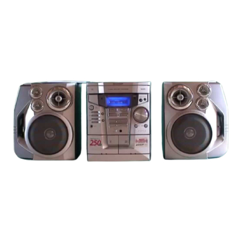
Sharp GX-68Z User manual

SHARP
SERVICE
MANUAL
S3928GX-68ZBK
5tlI
DOLBY
SYSTEM @
Dolby noise reduction manufactured under license from Dolby Labora-
tories Licensing Corporation.
“Dolby” and the double-D symbol
[xl
are trademarks of Dolby Labora-
tories Licensing Corporation.
GX=68Z(
BK)
CP-XS(BK)
/g
f-“---
I
I
In the interests of user-safetythe set should be restored to its original
condition and only parts identical to those specified be used.
INDEX TO CONTENTS
Page
SPEClFlCATlQNS ..................................................................2
STRINGING
OF
DIAL
CORD
.........................................................
,,QLTAGESELEC-IoN
............................................................
.
NAMES OF PARTS .............................................................*3,4
PROPER
USE
OF
THE
REMOTE
CONTROL ...........................................
.4
BLOCKDIAGRAM
.................................................................
DISASSEMBLY ................................................................
..6.7
ADJUSTMENT .............................................................
.*.&lo
,=,,NCTlQ,,,
TABLE
OF
IC..........................................................,
,
SCHEMATIC DIAGRAM/WIRING SIDE OF P.W.BOARD ...........................
-12-23
EQUIVALENT CIRCUIT (BLOCK DIAGRAM) OF
IC
...............................
*24-26
AC
POWER
SUPPLY
CORD
.......................................................
.26
EXPLODED VIEW ...........................................................
.27-29
REPLACEMENT
PARTS
LIST
...................................................
.30-37
SHARP
CORPORATION
FOR A COMPLETE DESCRIPTION OF THE OPERATION OF THIS UNIT, PLEASE
REFER TO THE OPERATION MANUAL.
SPECIFICATIONS
AC
11
OV-
127V/22OV-24OV,
50/60
Hz
DC 15V (External DC input)
DC
1.5V
(UM/SUM-3
or
R6
x
1)
(for clock/
timer)
Power consumption: 130 W
Output power: PMPO; 240W
(12OW
+
12OW)
(AC operation)
Radio
Frequency range: FM; 88
-
108 MHz
MW; 526.5
-
1,606.5
kHz
SWl;
2.3
-
7.3 MHz
SW2; 7.3
-
22 MHz
General
Power source:
MPO; 120W
(6OW
+
6OW)
(AC
operation)
RMS; 40W
(2OW
+2OW)
(AC
operation, 10% T.H.D.)
Input sensitivity and impedance:
CD/LINE IN; 530
mV/47
kohms
Loaded impedance: Headphones; 8
-
50 ohms
(recommended 32 ohms)
Dimensions: Width; 290 mm
(11-7/l
6”)
Height; 280 mm (1
l-l/l
6”)
Depth; 230 mm
19-
1
/16”1
Weight: 6.4 kg (14.1
Ibs.)
_
Tape
recorder
Tape: Compact cassette tape
Frequency response: 50
-
15,000 Hz
(CrO,
tape)
50
-
14,000 Hz (Normal tape
)
Signal/noise ratio: 55
dB
(TAPE 1, playback)
50
dB
(TAPE 2, recording/playback)
Wow and flutter: 0.25% (WRMS)
Speaker
system
Type.:
2-way
bass reflex type
Speakers: 12 cm
(4-3/4”)
woofer
x
2
5 cm
(2”)
tweeter
x
2
Rated power: 2ow
Impedance: 4 ohms
Dimensions: Width;
180
mm
(7-l/8”)
Height; 280 mm
(11
-l/16”)
Depth; 207 mm
(8-3/16”)
Weight: 2.5 kg (5.5
Ibs.)/each
Specifications for this model are subject to change without
prior notice.
STRINGING OF DIAL CORD
1. Turn the drum full-y in the direction
@
shown in Fig. 2-l and
stretch its cord over the parts in the numerical order.
2. Then turn the tuning control shaft fully in the direction
@
shown in Fig. 2-1 and fix its pointer as shown in Fig.
2-1.
DIAL PDINTER
TlJNERFwl3
E!RACKET<232)
/
blAL
Co
ASS Y
(202)
Figure
Z-
1
(*“)
VOLTAGE SELECTION
Before operating the unit on mains, check the preset voltage.
If the voltage is different from your local voltage, adjust the
voltage as follows: Slide the AC power supply socket cover
by slightly loosing the screw to the visible indication of the
side of your local voltage.
-2-

NAMES OF PARTS
1.
AM/PM
Indicator
2.
Clock/Timer
Displav
3.
Timer
Indicator:
6
4.
Sleep
Off
Button
5.
Sleep
On
Button
6.
Hour
Button
7.
Timer
Adjust
Button
8.
Clock
Adjust
Button
9.
Minute
Button
10.
Power
Switch
and
indicator
11.
Timer
Switch
and
Indicator
12.
Dolby
NR
Switch
and
Indicator
13.
FM
Stereo
Indicator
14.
Dial
Pointer
15.
Radio Band
Selector
16.
Fine
Tuning
Control
17.
Tuning
Control
18.
Function
Switches
and
Indicators
19.
Graphic
Equalizer
Controls
20.
Balance
Control
21.
Volume
Control
and
Indicator
22.
TAPE
2)
Cassette
Compartment
23.
TAPE
1)
Cassette
Compartment
24.
Record
Button:
0
25.-Play
Button:
)
26.
Rewind
Button:
44
27.
Fast
Forward
Button:
w
28.
Stop/Eject
Button:
n
/A
29.
Pause
Button:
II
30.
Reverse
Mode
Switch:
Ia
=a
31.
Play
Button:
4)
32.
Fast
Wind
Button:
44
33.
Fast
Wind
Button:
b
34.
Stop/Eject
Button:
n
/A
35.
Direction
Switch:
4,
36.
Direction
Indicators
37.
Headphone
Socket
38.
Extra Bass
Switch
and
Indicator
39.
Remote
Control
Sensor
and
Indicator
40.
VU
Meters
41.
Tape
Selector
Switch
42.
Mixing
Microphone
Socket
43.
Microphone
Volume
Control
44.
Pause
Indicator
45.
Tape
Speed
Switch
46.
CD/Line
Input
Sockets
47.
MW/SWl
Loop
Aerial
48.
FM/SW
Telescopic
Rod
Aerial
49.
Beat
Cancel
Switch
50.
Speaker
Lead
Holders
51.
Speaker
Terminals
52.
Battery
Compartment
53.
AC
Power
Input
Socket
54.
External
DC
Power
Input
Socket
1.
Bass
Reflex
Port
2.
Tweeter
3.
Woofer
4.
Speaker
Lead
1.
Remote
Control
Transmitter
Window
2.
Operate
Button
(Power
Switch)
3.
Volume
Up/Down
Buttons
4.
Pause
Button:
II
-3-
/
8
9
1.5
1617
///III
/II\\\\
PA
25
2627
2829
30
31
32
3334
35 36
_.
--
--
~~
TAPE
2
I
TAPE
I
1

DISASSEMBLY
Caution on Disassembly
Follow the below-mentioned notes when disassembling the
unit and reassembling it, to keep its safety and excellent
performance:
1. Take cassette tape of the unit.
2. Be sure to remove the power supply plug from the
wall outlet before starting to disassemble the unit and
remove the batteries from the unit.
3. Take off nylon bands, wire holders or connectors where
they need be removed when disassembling the unit.
After servicing the unit, be sure to rearrange the leads
where they were before disassembling.
4. Take sufficient care on static electricity of integrated
circuits and other circuits when servicing.
1
15
t
16
-t
i
(Allxl
03xlOmm
REMOVAL
I
PROCEDURE
1
FIGURE
1
Side Panel
(7. Screw
..+Al)xl4(
6-l
/
~‘““:::::::
2.
Socket........(C2)X4
6-3.7-1,
Power Amp. PWB
3. Flat Wire. . . . .
(C3)
X
3 6-3
1.
Screw . . . . . . .
.iDl)
X9
6-2.6-3,
7-l
Volume PWB
Timer PWB
2.
Socket........(D2)Xl
6-3
1. Knob . . . . . . .
(El
)
x
, 7-2
2. Nut
. . . . .
*
.
*
. .
(E2)
x
1
3.
Socket*..-....(EB)Xl
/
4. Flat Wire ......
(E4)
X
2
/
1. Screw
........(F~)x
2
/
7-4
5_~
3. Flat
Wire......(HB)X4
7-1.7-3
Mechanism Block
I
1. Screw .
. . . . .
..(KliX71
7-4
j
HeadphonesPWB
Tape Switch PWB
Microphone PWB
1. Screw
. . . . . . . .
(Ll)X,
7-4
I.
Screw..
. .
*.
.
.(Ml
)
X
1 7-4
1. Screw
. . . . . . . .
(Nl)xl
7-4
Level Meter PWB
/
1. Hook
. . . . . .
..(Pl)X41
7-4
1
Remote Control
PWR
1. Hook
.......
.(0,)x2!
7-4
(
LED PWB
/
1.
Screw. . . . .
..(Rl)xl
1
7-4
1
k(Al)x2
03xl2mm
I
(Cl1x3
63x8mm
Figure 6-1
hop
Cabinet
Front
Panel
Main Chassis
*Each P.W.B should be removed until the parts to be
exchanged can be removed when servicing. If the parts to
be exchanged are in the exchangeable condition, the rest
of P.W.Bs need not to be removed.
Power
Transformer
(Dl)xZ
03x8mm
Figure
6-2
(Dl)x
I
03x6mm
.(Cl)X2
03x6mm
-6-

1
L
I
I
I
I’
+82
Figure 5 BLOCK DIAGRAM
-5-

37
38
39
41
4243
50-
-50
46 47
48 49
A7
-
-
PROPER
REMOTE
1
/\
1
OPERATE
I
z---n
rVOLUME
DOWN VP
1
TAPE
PAUSE
II
4----o
c
CONTROL
Aim (within range of 60’ with no obstacles) the remote control
at the remote control sensor and operate as shown.
Notes concerning use:
0
Replace the batteries if control distance decreases or oper-
ation becomes erratic.
0
Periodically clean the transmitter window on the remote
control and the sensor on the main unit with soft cloth.
l
Exposing the sensor on the main unit to strong light can
interfere with operation. Reposition the unit away from the
strong light source.
0
Keep the remote control away from moisture, excessive heat,
shock, and vibrations.
0
The remote control’s usable range is between 0.4 m
(I
.4
feet)
and 6 m
(20
feet) away from the sensor.
60"
-4-

Front
Panel
-
AM
Motchlng
PWB
/
, Bock Chossis
%+qy
Chassis
(Dl)xZ
8-
A-
fa3
xl0mm
Figure 7
-
1
@“)”
Front Panel
&E2)
x
I
(Gllx2
63x6mm
(Hl)xl
pr3x6mm
Power
Switch PWB
Volume PW
B
+iMain
PWB
Figure
7-2
(Jllx2
Front Panel
83xlOm
F%P
!Hl\x
I
@3x6mm
Figure 7-3
Timer PWB
-(Fi)x2
11x2
3xlOmm
(Kllx7
‘Q3x12mm
LED
PWB,
w
(Rl)xl
03x8mmd
Microphone PW
B--f
03x8mm
(Milxl
(Nl)x I WB
1)x2
3
x6mm
03xlOmm
Level
Meter
PWB
PWB
Figure 7
-
4
-7-

1
MAIN
PWB-Al
CD/LINE
IN
J281
n
,EMITTER
COLLECTOR
Q514
#
VRIOI
(u
VR102
Figure
10
ADJUSTMENT POINTS
-lO-

MECHANISM
SECTION
TAPE
SECTION
. Driving Force check
I
Position of each switch or control
Volume
Beat cancel switch
1
Max
/
A
I
Toraue
Meter
I
Soecified
value
I
Play: TW-2412
Reverse play: TW-2422
. Torque Check
Over 50
g
Over
60
g
Graphic equalizer
Tape selector switch
Function
Dolby
NR
Swrtch
Center
Normal
Tape
Off
Torque Meter Specified value
Taoe 1
Taoe 2
-a
/
Play: TW-2111 35 to
60
g.cm
30 to
60
g.cm
Reverse play: TW-2121 35 to 60
g.cm
30 to 60
g.cm
Fast forward: TW-2231 55 to 120
g.cm
55 to 120
q.cm
*
Bias
Oscillation Frequency check
Adjustment
ooint Specified value
Rewind: TW-2231
+
Head Azimuth
55 to 120
g.cm
/
55 to 120
g.cm
1
L341
B:
104
t_
1.5 kHz
Beat cancel
-
A: -2
+
4
kHzforB
-
c:-8
&
2
kHzfor
B
Test Tape
MTT-114
Instrument Connection
J602
(Ext.
SP)
(Load resistance: 4 ohms)
9
Bias Current check
Adjustment
nnint
Specified value
I
. Tape Speed
+z”“#L
Resistor for L:
VRlOl
Normal
CrO2
measurement: 10 ohm
R:
VR102 460
&
50
,~A/720
+
75
.uA
Test Tape Adjusting Point Specified value Instrument
Connection
Normal
J602
speed MTT-111 Tape 2: VR502 3,000
f
60 Hz
(Ext.
SP)
+
Erase Current check
t
,
II
1
(Load
I
I
Specified value
1
j
;ftil
j
/
MTT-111 Tape 2: VR501 6,000
f
700 Hz
/ /
;f;:;;e’
j
Resistor for
measurement: 1 ohm Normal
1
CrOz
25*4mA145+7mA
To
set normal speed, short-circuit collector and emitter of Cl51 4.
-
Playback Amplifier Sensitivity check
I
Test Tape
I
Specified value
I
Instrument Connection
I
*
Tape
1
Playback Amplifier Sensitivity
Test Tape Adjusting Specified value Instrument
Point Connection
MTT-
150
L: VR201 Normal: 580 mV L: TP201
@
R:
VR202
R:
TP201 @
*
Tape 2 Playback Amplifier Sensitivity
Test Tape Adjusting Specified value Instrument
Point Connection
MTT- 150 L: VR203 Normal: 580 mV L: TP201
@
R:
VR204
R:
TP201
@
. Record/Playback Sensitivity
CASSETTE HOLDER COVER
Test Tape Adjusting
Point Specified value Instrument
Connection
MTT-502
72
HEAD
Ti
REVERSE
i-1
FF
(FFI
HEAD
REVERSEI
HEAD
Figure 9 AZIMUTH POINTS
-9-

TUNER
SECTION
ADJUSTMENT
fL:
Low-range frequency
fH:
High range frequency
. AM IF/RF
Test Stage Specified value/
Adjusting Point instrument Connection
IC 7-9
/
Input: Antenna
I
II
MW band
I.3
I
fL:
L5
/
Output: Pin 5 of IC2
coverage
1
fH: TC3
*
FM IF/RF
Test Stage
IF
Detection
Band coverage
Tracking
Specified value/
Adjusting Point Instrument Connection
Tl
T2
fL:
L2 Input: Antenna
fH: TC2Output: Pin 9 of IC2
88.0 MHz:
Ll
108.0 MHz:
TCl
I
TIMER
PWB-~3
I
,
40&,
,/’
‘)
IC551
. Clock Reference Frequency
Adjusting Point Specified value Instrument Connection
TC551 32,768 kHz
+
0.15 Hz
1
Pin 40 of IC551
Figure 8-l ADJUSTMENT POINTS
/TUNER
PwB-cl
Figure 8-2 CLOCK REFERENCE FREQUENCY
I
TC5
Figure 8-3 ADJUSTMENT POINTS
-8-

FUNCTION TABLE OF
IC
IX1
436AF
l
FUNCTIONS AND RECEPTION CODE
-ll-
-.---
-.~__

NOTES ON SCHEMATIC DIAGRAM
. Resistor: . Parts marked with
“A”
(-243)
are important for
maintaining
To differentiate the units of resistors, such symbol as
K
is the safety of the set. Be sure to
rePlaCe
these parts with
used: the symbol
K
means 1000 ohm and the resistor specified ones for maintaining the safety and performance
without any symbol is ohm-type resistor. of the set.
. Capacitor:
*
Schematic diagram and Wiring Side of
P.W.Board
for this
To indicate the unit of capacitor, a symbol
P
is used: model are subject to change for improvement without
prior
this symbol
P
means micro-micro-farad and the unit of notice.
the capacitor without such a symbol is microfarad. As to
electrolytic capacitor, the expression “capacitance/withstand
voltage” is used.
(CH),
(TH),
(RH),
(UJ):
Temperature compensation
(ML): Mylar type
(P.P.):
Polypropylene type
*
The indicated voltage in each section is the one measured by
Digital
Multimeter
between such a section and the chassis
with no signal given.
SLC22UR
LD701
DU
LD701
UR
SLR34UR7
SLR34UR3
SLR54DC4
SLT35UR3
2SD2061
E
FRON
VIEW
a
8
CE
2SC2785
EF
2SC2240
BL
rl
2SC2001
K
FRONT
2SB562
C
VIEW
DTC124
XS
II-n-f
ECB
DTC114
YS
2SD1858
R3
2562878
B
2SC.1815 GR
2SA933
SR
(l)(2)(3)
2S8824
S
Figure 12 TYPES OF TRANSISTOR AND LED
-12-

-.----
--
L--C”
,281
CD/
iiN
iw
R--C”
-
A
C
E
F
G
H
1
I
2
I
3
I
4
I
5
l
NOTES ON SCHEMATIC DIAGRAM can be found on page 12.
-13-

Iii
r
i
I
7
I
8
I
9
I
10
I
SCHEMATIC
11
I
12 I’
1
DIAGRAM
(l/3)
5
-14-

A
1
I
2
I
3
I
4
I
5
I
6
I
Figure 15 WIRING SIDE OF
P
-15-

P23
I-b
r--------’
I
I
P.W:BOARD
I
8
9
I
10
11
I
12
1
IDE
OF
(l/3)
-16-

C
PI4
11-a
c1
B
D
F
G
P14
11-D
-
H
1
I
2
I
3
I
4
I
5
I
6
l
NOTES ON SCHEMATIC DIAGRAM can be found on page 12.
Figure
17 SCHEh
-17-

El
--B
I
ii
1
Q601.
Q602:MUTING
r
Q603.
Q604:GAIN
CONTROL
-
-
I
i20
OK
-
-
-
-
I
7
I
8
I
9
I
10
I
11
I
12
J
SCHEMATIC DIAGRAM
(Z/3)
-18-

A
B
C
D
E
F
G
!
H
1
I
2
I
3
I
4
I
5
I
6
I
Figure
19
WIRING SIDE OF P.\
-19-

I
00
,
Other manuals for GX-68Z
1
This manual suits for next models
3
Table of contents
Other Sharp Stereo System manuals

Sharp
Sharp CD-C470H User manual

Sharp
Sharp CD-C452 User manual

Sharp
Sharp CD-C500Z User manual

Sharp
Sharp CD-DP900S User manual

Sharp
Sharp VZ-1600H User manual

Sharp
Sharp CD-BA3100 User manual

Sharp
Sharp XL-MP110E User manual

Sharp
Sharp CD-XP300W User manual

Sharp
Sharp XL-B510 User manual

Sharp
Sharp XL-HP550E User manual

Sharp
Sharp XL-T300H User manual

Sharp
Sharp XL-HF300PH(S) User manual

Sharp
Sharp CD-DP900E User manual

Sharp
Sharp QT-CD210H User manual

Sharp
Sharp CD-XP500 User manual

Sharp
Sharp XL-B512 User manual

Sharp
Sharp CD-C250X BK User manual

Sharp
Sharp XL-HP404V User manual

Sharp
Sharp CD-RW5000 User manual

Sharp
Sharp CD-C5H User manual