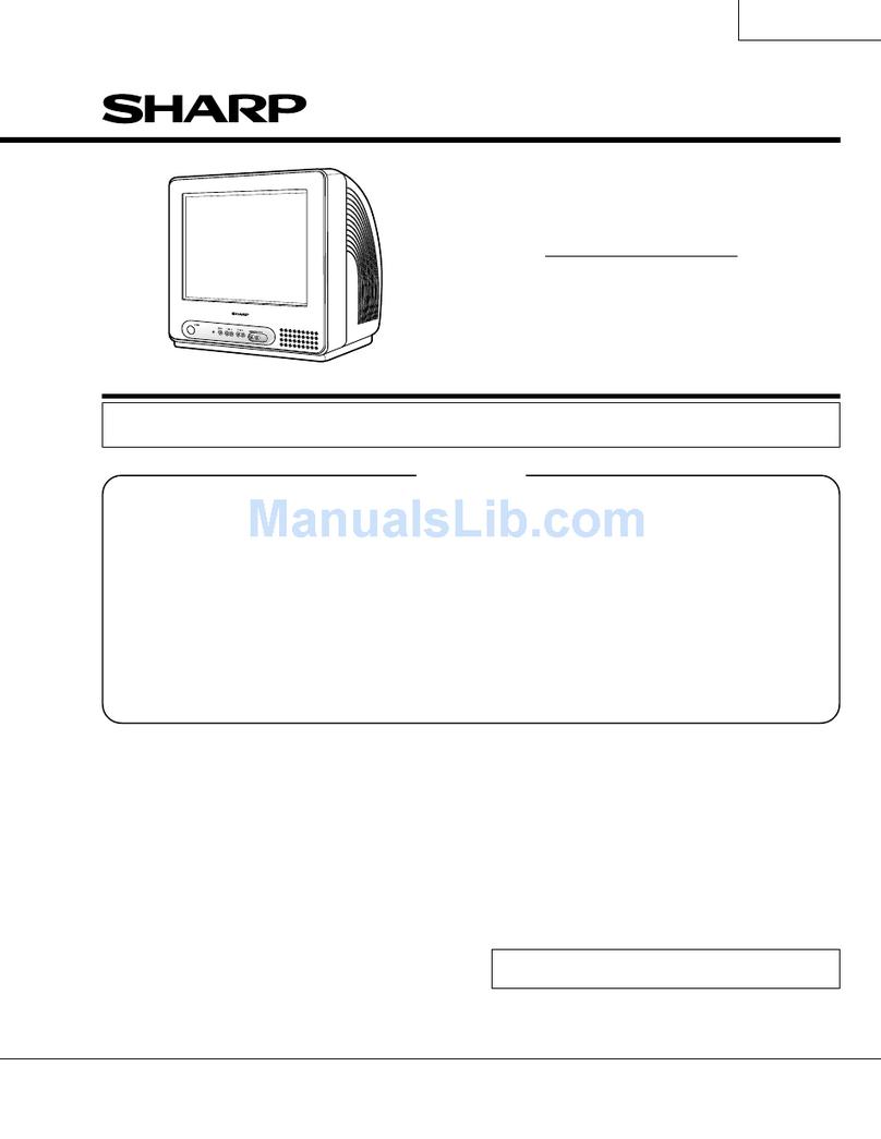
Sharp 29WF200 User manual

1
29WF200
29WF500
SHARP CORPORATION
SERVICE MANUAL
29WF200
29WF500
MODELS
In the interests of user-safety (Required by safety regulations in some countries) the set should be restored
to its original condition and only parts identical to those specified should be used.
FEATURES
ËPAL-B/G, NTSC (AV only) (29WF200)
ËWorld Multi 28 System (29WF500)
Ë100-CH Program Memory
ËAV Mode (Standard / Dynamic / Soft)
ËCATV Hyper Band Ready
ËPAL/NTSC 3 Line Comb Filter
ËOn/Off Velocity Modulation
ËBlack Stretch Circuit
ËPicture Noise Reduction
ËWhite Temp. Select
ËAperture Control
ËS-BOOSTER
ËOSD-Language (English ONLY)
ËOn/Off Reminder Timer
ËPower Save Mode
ËRear AV-IN 1 & 2, S-Video In, AV Output (Monitor Out),
Headphone and Front AV-IN 3
Ë3.5L Speaker Box
ËAFT
ËComponent Input Terminal
ËAV Stereo (29WF200)
ËNICAM/A2 (29WF500)
WARNING
The chassis in this receiver is partially hot. Use an isolation transformer between the line cord plug and power
receptacle, when servicing this chassis. To prevent electric shock, do not remove cover. No user – serviceable
parts inside. Refer servicing to qualified service personnel.
»SPECIFICATIONS ...........................................2
»IMPORTANT SERVICE NOTES ......................2
»ADJUSTMENT PRECAUTIONS .....................3
»TROUBLE SHOOTING FLOWCHART..........15
»SOLID STATE DEVICE BASE DIAGRAM.....19
»WAVEFORMS ...............................................20
»CHASSIS LAYOUT........................................22
»BLOCK DIAGRAM.........................................24
»DESCRIPTION OF SCHEMATIC DIAGRAM .. 26
»SCHEMATIC DIAGRAM
ËCRT UNIT.................................................27
ËMAIN UNIT ...............................................28
ËAV COMB UNIT........................................36
ËS-CONTROL UNIT ...................................40
ËFRONT UNIT............................................44
»PRINTED WIRING BOARD ASSEMBLIES ...48
»REPLACEMENT PARTS LIST
ËELECTRICAL PARTS............................... 56
ËMISCELLANEOUS PARTS ......................66
ËSUPPLIED ACCESSORIES.....................66
ËPACKING PARTS.....................................66
ËCABINET PARTS .....................................66
»PACKING OF THE SET ................................67
Page Page
CONTENTS
COLOUR TELEVISION
Chassis No. GB-1
S14N129WF200/0//
29WF200 29WF500

2
29WF200
29WF500
2-1 2-2
SPECIFICATIONS
Convergence .................................................................Self Convergence System
Focus.........................................................Bi-Potential, Uni-Potential Electrostatic
Sweep Deflection......................................................................................Magnetic
Intermediate Frequencies
Picture IF Carrier ..................................................................................38.9MHz
Sound IF Carrier Frequency
5.5MHz ............................................................................33.4MHz(29WF200)
6.5MHz ............................................................................32.4MHz(29WF500)
6.0MHz ............................................................................32.9MHz(29WF500)
5.5MHz ............................................................................33.4MHz(29WF500)
4.5MHz ............................................................................34.4MHz(29WF500)
Colour Sub-Carrier Frequency
PAL ..................................................................................................34.47MHz
NTSC...............................................................................................35.32MHz
Power Input..................................................................... 110 ~ 240V AC 50/60 Hz
Power Consumption ....................................................................158W(29WF200)
165W(29WF500)
Audio Power Output Rating ....................................................... 10W X 2 (at Max.)
Speaker
Size.....................................................................8 x 12 cm + 5cm round (2pcs.)
Aerial Input Impedance
VHF/UHF .......................................................................... 75 ohms Unbalanced
Receiving Channel
PAL-B/G
VHF-Channels.............................................................................. E2 thru E12
UHF-Channels............................................................................. E21thru E69
CATV ........................................................................ X thru Z +2, S1 thru S41
PAL-B/G, SECAM-B/G
VHF-Channels............................................................ E2 thru E12(29WF500)
UHF-Channels.......................................................... E21 thru E69(29WF500)
CATV .................................................... X thru Z + 2, S1 thru S41 (29WF500)
PAL-D/K, SECAM-D/K
VHF-Channels...................................... R1 thru R12, C1 thru C12(29WF500)
UHF-Channels........................................21 thru 69, C21 thru C57(29WF500)
PAL-I, SECAM-I
VHF-Channels................................................ (IRELAND) B thru J(29WF500)
UHF-Channels.......................................... (U.K.& H.K.) 21 thru 69(29WF500)
NTSC-M
VHF-Channels..........................................................2 thru 13(US)(29WF500)
1 thru 12 (Japan)(29WF500)
UHF-Channels........................................................14 thru 69(US)(29WF500)
13 thru 62 (Japan)(29WF500)
CATV ............................................. A-6 thru A-1, A thru W+29(US)(29WF500)
C13 thru C63 (Japan)(29WF500)
Receiving Frequency
VHF ....................................................................... 44.25 MHz thru 423.25 MHz
UHF ..................................................................... 431.25 MHz thru 863.25 MHz
Dimensions...................................................................................... Width: 800mm
Height: 583mm
Depth: 506mm
Weight(approx): 47 kg
Specifications are subject to change without prior notice.
IMPORTANT SERVICE NOTES
Maintenance and repair of this receiver should be done by qualified
service personnel only.
SERVICE OF HIGH VOLTAGE SYSTEM AND PIC-
TURE TUBE
When servicing the high voltage system, remove static charge from it by
Connecting a 10K ohm Resistor in series with an insulated wire(such as a
test probe) between picture tube dag and 2nd anode lead. (AC line cord
should be disconnected from AC outlet.)
1. Picture tube in this receiver employs integral implosion protection.
2. Replace with tube of the same type number for continued safety.
3. Do not lift picture tube by the neck.
4. Handle the picture tube only when wearing shatterproof goggles and after discharging
the high voltage completely.
X-RAY
This receiver is designed so that any X-Ray radiation is kept to an absolute
Minimum. Since certain malfunctions or servicing may produce potentially
hazardous radiation with prolonged exposure at close range, the followin
precautions should be observed:
1. When repairing the circuit, be sure not to increase the high voltage to more than 33.0kV
(at beam 0 µA) for the set.
2. To keep the set in a normal operation , be sure to make it function on 30.0kV ±1.5kV (at
beam 1,700 µA) in the case of the set. The set has been factory - Adjusted to the above-
mentioned high voltage.
∴∴
∴∴
∴If there is a possibility that the high voltage fluctuates as a result of the repairs,
never forget to check for such high voltage after the work.
3. Do not substitute a picture tube with unauthorized types and/or brands which may cause
excess X-ray radiation.
BEFORE RETURNING THE RECEIVER
Before returning the receiver to the user, perform the following safety Checks.
1. Inspect all lead dress to make certain that leads are not pinched or that hardware is not
lodged between the chassis and other metal parts in the receiver.
2. Inspect all protective devices such as non-metallic control knobs, insulating fishpapers,
cabinet backs, adjustment and compartment covers or shields, isolation resistor- ca-
pacity networks, mechanical insulators etc.

3
3-1 3-2
29WF200
29WF500
ADJUSTMENT PRECAUTIONS
This model’s setting are adjusted in two different ways: through the I2C bus control and in the
conventional analog manner. The adjustments via the I2C bus control include preset-only items
and variable data.
1. Setting the service mode by the microprocessor.
1When the JA366 and JA367 are short-circuited, enter into the service mode.
(Adjustment through the I2C bus control).
(Use JWS Key to set as well).
2Press the CH DOWN / UP key on the remote controller to get ready to select the
mode one by one.
3Press the CH DOWN / UP key on the remote controller to select the modes
reversibly one by one.
4Using the VOLUME UP/ DOWN key on the remote controller, the data can be modi-
fied.
5When the short circuit between the JA366 and JA367 is cut off, it will be released
from the service mode.
2. Factory Presetting.
1Short JA366 & JA367 and turn on the main power switch.
Initial values are automatically preset, only when a new EEPROM is used (Judge
with the first 4 bytes).
2The initial data are preset as listed in page 5 to 8.
3Make sure whether the data need to modification or not (Initial data).
Note: Once the chassis has been assembly together and ready to be POWER ON for the FIRST TIME,
make sure to short JA366 & JA367 to switch to the service mode position first and then turn on the
main power switch. (See 2-11
11
1above).
Precaution: If haven’t done this initialization, it may possibly generate excessive Beam current.
SERVICE MODE
(1) In the Service Mode, Key is used to select the mode in the following order.
CUT OFF
MODE 50Hz ADJ.
MODE
60Hz ADJ.
MODE SUB ADJ.
MODE
SERVICE MODE 2
(refer to page 5)
INFOMATION
MODE
SERVICE MODE 1
OPTION MODE 2
(refer to page 4) OPTION MODE 1
(refer to page 4)
CUT OFF MODE
R-CUT OFF
G-CUT OFF
B-CUT OFF
3 sec. TIME OUT CUT OFF
BKGD
MODE
3 sec. TIME OUT G-DRIVE
B-DRIVE
CUT OFF
DATA
LENGTH
63 ~ 255
INITIAL
DATA
63
DRIVE
DATA
LENGTH
0 ~ 127
INITIAL
DATA
63
" _ / _ _ "
LATERAL MODE
(R, G, B-CUT OFF)
KEY
R-CUT OFF
G-CUT OFF
B-CUT OFF
G-DRIVE
B-DRIVE
UP
1 KEY
2 KEY
3 KEY
7 KEY
8 KEY
DOWN
4 KEY
5 KEY
6 KEY
F/B KEY
0 KEY
MENU button
of R/C MENU button
of R/C
MENU button
of R/C
MENU button
of R/C
MENU button
of R/C

4
29WF200
29WF500
4-1 4-2
V - SIZE 50Hz (V-SIZE 50)
↓
V-LINEARITY 50Hz (V-LINE 50)
↓
V S-CORRECTION 50Hz (V S-CORR 50)
↓
V-POSITION 50Hz (V-CENT 50)
TRAPEZIUM 50Hz (TRAPE 50)
↑
E/W CORNER 50Hz (E/W COR 50)
↑
E/W PARABOLA 50Hz (E/W PARA 50)
↑
H-SIZE 50Hz (H-SIZE 50)
↑
H-POSITION 50Hz (H-CENT 50)
V - SIZE 60Hz (V-SIZE 60)
↓
V-LINEARITY 60Hz (V-LINE 60)
↓
V S-CORRECTION 60Hz (V S-CORR 60)
↓
V-POSITION 60Hz (V-CENT 60)
TRAPEZIUM 60Hz (TRAPE 60)
↑
E/W CORNER 60Hz (E/W COR 60)
↑
E/W PARABOLA 60Hz (E/W PARA 60)
↑
H-SIZE 60Hz (H-SIZE 60)
↑
H-POSITION 60Hz (H-CENT 60)
SECAM R-Y (SCM R-Y)
↓
SECAM B-Y (SCM B-Y)
↓
SECAM BELL (SCM BELL)
↓
SUB BRIGHT (SUB BRI)
↓
SUB BRIGHT (DVD) (SUB BRI DVD)
↓
SUB CONT (SUB CONT)
↓
SUB CONT (DVD) (SUB CONT DVD)
SUB ADJ.
MODE
PIF VCO (PIF VCO)
↑
SUB VOLUME (SUB VOL)
↑
RF SUB SOUND (RF S-SOUND)
↑
RF AGC (RF AGC)
↑
SUB COLOUR (DVD) (SUB COL DVD)
↑
SUB COLOUR (SUB COL)
↑
SUB TINT (DVD) (SUB TINT DVD)
↑
SUB TINT (SUB TINT)
FORWARD: CH DOWN KEY
REVERSE: CH UP KEY
FORWARD: CH DOWN KEY
REVERSE: CH UP KEY
FORWARD: CH DOWN KEY
REVERSE: CH UP KEY
60Hz ADJ.
MODE
50Hz ADJ.
MODE
USER DATA IN SERVICE MODE OPTION
• While SERVICE MODE 1 on, EEPROM DATA will switch to the service data.
Also, once press the menu button at the remote controller, EEPROM will switch to SERVICE MODE OPTION.
Once press the menu button again at the remote controller, EEPROM will switch back to SERVICE MODE 1.
• In the service option the user data establish as below,
No. SERVICE MODE EEPROM ITEM OSD DATA INITIAL DATA
1 OPTION MODE 1 WHITE TEMP SETTING WT LOW/HIGH HIGH
2 S-BOOST OPTION S-BOOST OFF/ON ON
3 PIF FREQ. SETTING PIF 33.50MHz ~ 58.75MHZ 38.9MHz
4 SPRIT/INTER CARRIER S/I SPRIT/INTER
SPRIT
5 FORCED COLOUR KILLER F-ID OFF/ON OFF
6 TEXT OPTION TEXT OFF/ON OFF
7 NICAM OPTION NICAM OFF/ON OFF
8 A2 STEREO OPTION A2 OFF/ON OFF
9 MONO BILINGUAL OPTION MONO-BIL OFF/ON OFF
10 OPTION MODE 1 SECAM OPTION SECAM OFF/ON ON
11 RF-NTSC OPTION RF NTSC OFF/ON ON
12 SOUND SYSTEM SETTING S-SYS BG / I / DK / M BG I DK M
13 ROTATION OPTION ROTATION OFF/ON OFF
14 SERCH SPEED SETTING S SPD 350kHz / 450kHz / 550kHz 450kHz
15 HOTEL MODE OPTION H MODE OFF/ON OFF
16 HOTEL MODE POSITION H POSITION 0 ~ 99 / — 0
17 HOTEL MODE VOLUME H VOLUME 0 ~ 60 0
18 OSD LANGUAGE LANGUAGE E / C / F / R / M / A E C F R M A
19 COMB COMB OFF/ON ON
20 AI AI OFF/ON ON
Service Mode Option MENU
Option setting data
No. OSD SETTING DATA
29WF200 29WF500
1 WT HIGH HIGH
2 S-BOOST ON ON
3 PIF 38.9MHZ 38.9MHz
4 S/I SPRIT SPRIT
5 F-ID OFF OFF
6 TEXT OFF OFF
7 NICAM OFF ON
8 A2 OFF ON
9 MONO-BIL OFF OFF
10 SECAM OFF ON
11 RF NTSC OFF ON
12 S-SYS BG BG I DK M
13 ROTATION OFF OFF
14 S SPD 550kHz 550kHz
15 H MODE OFF OFF
16 H POSITION 0 0
17 H VOLUME 0 0
18 LANGUAGE E E
19 COMB ON ON
20 AI ON ON

5
5-1 5-2
29WF200
29WF500
#1 R CUT (63 ~ 255), G CUT (63 ~ 255), B CUT (63 ~ 255), G DRV (0 ~ 127), B DRV (0 ~ 127)
#2 R CUT (63), G CUT (63), B CUT (63), G DRV (63), B DRV (63)
#3 WHILE ADJUSTING SECAM R-Y, SECAM B-YAND SUB-TINT, Y-MUTE OF 1 CHIP IS SET TO ON.
#4 WHILE CHOOSING PIFVCO MODE, RF AGC SETTO "0 0"AND PIFVCO IS SET TO "1".
#5 ADJUSTMENT FOR 60Hz. IS CHANGE AUTOMATICALLY BY 50Hz.ADJUSTMENT AS BELOW.
60Hz. ADJ. OFFSET VALUE FROM 50HzADJ.
V-SIZE (60Hz) +3
V-LINEARITY (60Hz) +1
VS-CORRECTION (60Hz) +1
V-POSITION (60Hz) -1
H-POSITION (60Hz) +3
H-SIZE (60Hz) 0
E/W-PARABOLA (60Hz) +1
E/W-CORNER (60Hz) 0
TRAPEZIUM (60Hz) 0
AFTER SHORT JA 366 & JA 367, AND TURN ON THE MAIN POWER SWITCH, READ DATA
FROM EEPROM ADDRESS 00H ~ 03H, AND COMPARE TO THE LIST BELOW, IF
DIFFERENT, INITIALIZE THE EEPROM.
1. SERVICE MODE 1.
ADDRESS DATA
00H 3AH
01H 76H
02H 3BH
03H 76H
No. EEPROM SETTING DATA OSD IC DATA SETTING INITIAL
SETTING
LENGTH DATA DATA
1 CUT OFF #1 CUTOFF BKGD 1 CHIP CUTOFF/DRIVE #2 —
2 CUT OFF (DVD) #1 CUTOFF DVD BKGD 1 CHIP CUTOFF/DRIVE #2 —
3 V-SIZE (50Hz) 0 ~ 63 V-SIZE 50 1 CHIP V-SIZE 7 22
4 V-LINEARITY (50Hz) 0 ~ 15 V-LINE 50 1 CHIP V-LINEARITY 3 3
5
VS-CORRECTION (50Hz)
0 ~ 15 V S-CORR 50 1 CHIP
V S-CORRECTION
54
6 V-POSITION
(50Hz)
0 ~ 7 V-CENT 50 1 CHIP V-POSITION 3 4
7 H-POSITION
(50Hz)
0 ~ 31 H-CENT 50 1 CHIP H-P0SITION 11 8
8 H-SIZE (50Hz) 0 ~ 63 H-SIZE 50 1 CHIP H-SIZE 31 50
9 E/W-PARABOLA (50Hz) 0 ~ 63 E/W PAR 50 1 CHIP
E/W PARABORA
31 35
10 E/W CORNER (50Hz) 0 ~ 15 E/W COR 50 1 CHIP E/W CORNER 8 7
11
E/W TRAPEZIUM (50Hz)
0 ~ 31 TRAPE 50 1 CHIP
E/W TRAPEZIUM
517
12 SECAM R-Y #3 0 ~ 15 SCM R-Y 1 CHIP SECAM R-Y 8 8
13 SECAM B-Y #3 0 ~ 15 SCM B-Y 1 CHIP SECAM B-Y 8 8
14 SECAM BELL 0 ~ 1 SCM BELL 1 CHIP BELL F0 0 0
15 SUB BRIGHT 0 ~ 127 SUB BRI 1 CHIP BRIGHTNESS 80 80
16 SUB BRIGHT (DVD) 0 ~ 127 SUB BRI DVD 1 CHIP BRIGHTNESS 80 80
17 SUB CONT 0 ~ 15 SUB CONT 1 CHIP SUB CONTRAST 8 4
18 SUB CONT (DVD) 0 ~ 15 SUB CONT DVD 1 CHIP SUB CONTRAST 8 4
19 SUB TINT #3 0 ~ 127 SUB TINT 1 CHIP TINT 64 64
20 SUB TINT (DVD) #3 0 ~ 31 SUB TINT DVD 1 CHIP BB-TINT 16 16
21 SUB COLOUR 0 ~ 127 SUB COL 1 CHIP COLOUR 45 45
22 SUB COLOUR (DVD) 0 ~ 127 SUB COL DVD 1 CHIP COLOUR 45 70
23 RF AGC 0 ~ 63 RF AGC 1 CHIP RF AGC 46 34
24 RF SUB SOUND 0 ~ 127 RF S-SOUND 1 CHIP
IF AUDIO ATT
96 95
25 SUB VOLUME 0 ~ 255 SUB VOL
SOUND
VOLUME 60 255
26 PIF VCO #4 PIFVCO 1 CHIP #4 - -
27 V-SIZE (60Hz)#5 0 ~ 63 V-SIZE 60 1 CHIP V-SIZE 7 26
28 V-LINEARITY (60Hz)#5 0 ~ 15 V-LINE 60 1 CHIP V-LINEARITY 3 3
29
VS-CORRECTION (60Hz)#5
0 ~ 15 V S-CORR 60 1 CHIP
V S-CORRECTION
56
30 V-POSITION (60Hz)#5 0 ~ 7 V-CENT 60 1 CHIP V-POSITION 3 2
31 H-POSITION (60Hz)#5 0 ~ 31 H-CENT 60 1 CHIP H-POSITION 11 10
32 H-SIZE (60Hz)#5 0 ~ 63 H-SIZE 60 1 CHIP H-SIZE 31 50
33
E/W PARABOLA (60Hz)#5
0 ~ 63 E/W PAR 60 1 CHIP
E/W PARABORA
31 32
34
E/W CORNER (60Hz)#5
0 ~ 15 E/W COR 60 1 CHIP E/W CORNER 8 5
35 TRAPEZIUM (60Hz)#5 0 ~ 31 TRAPE 60 1 CHIP E/W TRAPEZIUM 5 17
36 V-ENT 0 ~ 7 V-ENT 1 CHIP V-ENT 6 6
37 H-ENT 0 ~ 7 H-ENT 1 CHIP H-ENT 5 5
1 WHITE PEEK CONTROL 0 ~ 1 WPS 1 CHIP WPS 1 1
2 SUB CONTRAST 0 ~ 127 S CONT 1 CHIP CONTRAST 127 127
3 NTSC PHASE 0 ~ 3 N-P NT 1 CHIP N PHASE 0 0
4 SUB SHARPNESS (TV) 0 ~ 63 S SHARP T 1 CHIP SHARPNESS 10 10
5 SUB SHARPNESS (AV) 0 ~ 63 S SHARPA 1 CHIP SHARPNESS 10 10
6 SUB SHARPNESS (DVD) 0 ~ 63 S SHARP D 1 CHIP SHARPNESS 10 10
7 RGB CONTRAST 0 ~ 63 RGB CONT 1 CHIP
RGB CONTRAST
32 42
8 Y-DL (B/G B/W) 0 ~ 3 Y B B 1 CHIP Y-DL 0 0
9 Y-DL (B/G PAL) 0 ~ 3 Y B P 1 CHIP Y-DL 1 0
10 Y-DL (B/G SECAM) 0 ~ 3 Y B S 1 CHIP Y-DL 0 0
11 Y-DL (B/G N443) 0 ~ 3 Y B N4 1 CHIP Y-DL 0 0
12 Y-DL (B/G N358) 0 ~ 3 Y B N3 1 CHIP Y-DL 0 0
13 Y-DL (I B/W) 0 ~ 3 Y I B 1 CHIP Y-DL 0 0
14 Y-DL (I PAL) 0 ~ 3 Y I P 1 CHIP Y-DL 3 3
15 Y-DL (I SECAM) 0 ~ 3 Y I S 1 CHIP Y-DL 0 0
16 Y-DL (I N443) 0 ~ 3 Y I N4 1 CHIP Y-DL 0 0
17 Y-DL (I N358) 0 ~ 3 Y I N3 1 CHIP Y-DL 0 0
18 Y-DL (D/K B/W) 0 ~ 3 Y DK B 1 CHIP Y-DL 0 0
19 Y-DL (D/K PAL) 0 ~ 3 Y DK P 1 CHIP Y-DL 3 0
20 Y-DL (D/K SECAM) 0 ~ 3 Y DK S 1 CHIP Y-DL 3 0
21 Y-DL (DK N443) 0 ~ 3 Y DK N4 1 CHIP Y-DL 0 0
22 Y-DL (DK N358) 0 ~ 3 Y DK N3 1 CHIP Y-DL 0 0
23 Y-DL (M B/W) 0 ~ 3 Y M B 1 CHIP Y-DL 0 0
24 Y-DL (M PAL) 0 ~ 3 Y M P 1 CHIP Y-DL 0 0
25 Y-DL (M SECAM) 0 ~ 3 Y M S 1 CHIP Y-DL 0 0
26 Y-DL (M N443) 0 ~ 3 Y M N4 1 CHIP Y-DL 1 1
27 Y-DL (M N358) 0 ~ 3 Y M N3 1 CHIP Y-DL 1 0
28 Y-DL (AV B/W) 0 ~ 3 YAB 1 CHIP Y-DL 0 0
29 Y-DL (AV PAL) 0 ~ 3 Y A P 1 CHIP Y-DL 0 0
30 Y-DL (AV SECAM) 0 ~ 3 Y A S 1 CHIP Y-DL 0 0
31 Y-DL (AV N443) 0 ~ 3 YA N4 1 CHIP Y-DL 0 0
32 Y-DL (AV N358) 0 ~ 3 YA N3 1 CHIP Y-DL 0 0
33 SECAM GP-PHASE 0 ~ 3 S G-PHASE 1 CHIP S GP-PHASE 1 1
34 SECAM ID-SENS 0 ~ 1 S ID-SENS 1 CHIP S ID-SENS 0 0
35 SECAM ID-MODE 0 ~ 1 S ID-MODE 1 CHIP S ID-MODE 0 0
36 P/N-ID 0 ~ 1 PN ID 1 CHIP P/N-ID 0 0
37 6.5M SIF FIX 0 ~ 1 6.5M 1 CHIP 6.5M S-FIX 0 0
38 DC RESTORATION 0 ~ 3 DC REST 1 CHIP
DC RESTORATION
33
39 BLACK STRETCH 0 ~ 3 S ST 1 CHIP
BLACK STRETCH
12
40 ABL START POINT 0 ~ 3 ABL ST 1 CHIP
ABL START POINT
32
41 ABL GAIN 0 ~ 3 ABL GA 1 CHIP ABL GAIN 2 2
42 COLOUR GAMMA 0 ~ 1 COL G 1 CHIP COLOUR GAMMA 1 1
43 V RAMP REF. VOLTAGE 0 ~ 1 V RAMP 1 CHIP V RAMP 1 1
44 VSM PHASE 0 ~ 1 VSM PHASE 1 CHIP VSM PHASE 0 0
45 AUDIO ATT 0 ~ 127 ATT 1 CHIP IF AUDIOATT 0 0
46 DATAILS CORING 0 ~ 63 WECOR COMB/AI WECOR 32 5
47 DATAILS DIFF FREQ. 0 ~ 1 DCNG COMB/AI DCNG 1 1
48 DATAILS GAIN 0 ~ 7 SPAL COMB/AI SPAL 6 2
2. SERVICE MODE 2.
HOTEL MODE
When hotel mode is ON;
— Maximum volume data is determined by option setting H VOLUME.
— Channel position after POWER ON is determined by option setting H POSITION
(if option setting HOTEL-POS is not set, processing is according to last position data).
— PRESET mode is disabled.
— CH SETTING menu is not available.
No. EEPROM SETTING DATA OSD IC DATA SETTING INITIAL
SETTING
LENGTH DATA DATA

6
29WF200
29WF500
6-1 6-2
49 DATAILS LIMIT 0 ~ 15 PKLM COMB/AI PKLM 8 4
50 OUTLINE DFF FREQ. 0 ~ 1 YDO COMB/AI YDO 0 1
51 OUTLINE CORING 0 ~ 7 RCOR COMB/AI RCOR 5 4
52 OUTLINE CORRECTION 0 ~ 15 RMY COMB/AI RMY 14 14
53 DATAILS OUTLINE 0 ~ 255 GAINA COMB/AI GAINA 64 90
54 YNR CORING 0 ~ 7 BLC COMB/AI BLC 4 0
55 CHROMA BPF TV 0 ~ 3 BPS T COMB/AI BPS T 0 3
56 CHROMA BPFAV 0 ~ 3 BPS A COMB/AI BPS A 0 0
57 Y-DELAY TV 0 ~ 7 YDL T COMB/AI YDL T 4 4
58 Y-DELAY AV 0 ~ 7 YDLA COMB/AI YDLA 3 3
59 V OUTLINE LIMIT 0 ~ 15 VPL COMB/AI VPL 8 8
60 V OUTLINE CORING 0 ~ 15 KOA COMB/AI KOA 2 7
61 V OUTLINE DETECT 0 ~ 1 YHO COMB/AI YHO 1 1
62 YNR DETECT GAIN 0 ~ 3 YNG COMB/AI YNG 2 0
63 YNR CORING 0 ~ 15 COR COMB/AI COR 8 1
64 B-STRETCH REFLECT 0 ~ 3 APSL COMB/AI APSL 1 1
65 B-STRETCH THRE 0 ~63 APMN COMB/AI APMN 20 20
66
PEDESTAIL CORRECTION
0 ~ 7 PHD COMB/AI PHD 6 6
67 B-STRETCH INITIAL 0 ~ 31 APA COMB/AI APA 6 4
68 AI ON/OFF 0 ~ 1 AION COMB/AI AION 0 1
69 HISTGRAM LIMIT 0 ~ 63 LMT COMB/AI LMT 12 15
70 Y-MIN DETECT GAIN 0 ~ 3 MNSL COMB/AI MNSL 2 1
71 Y-MIN LIMIT 0 ~ 63 MINLT COMB/AI MINLT 32 32
72 BASE AMOUNT 0 ~15 BSE COMB/AI BSE 15 15
73 Y-MIN DETECT OFFSET 0 ~15 MNOFT COMB/AI MNOFT 6 9
74 APL LAST GAIN 0 ~ 1 APGA COMB/AI APGA 1 1
75 APL LIMIT LAST GAIN 0 ~ 63 APLT COMB/AI APLT 10 32
76 APL SWITCH LAST GAIN 0 ~ 127 APDT COMB/AI APDT 37 10
77 LOW APL COL LEVEL 0 ~ 63 APC COMB/AI APC 28 10
78 LOW APL COL GAIN 0 ~ 3 CAS COMB/AI CAS 0 2
79 HIGH APLCOL LEVEL 0 ~ 63 APU COMB/AI APU 54 5
80 HIGH APLCOL GAIN 0 ~ 3 CUS COMB/AI CUS 2 2
81 PRESCALE SCART 0 ~ 127 PRE S NICAM PRESCALE 24 24
82 PRESCALE FM/AM 0 ~ 127 PRE F NICAM PRESCALE 10 10
83 PRESCALE NICAM 0 ~ 127 PRE N NICAM PRESCALE 63 24
84 AUTO VOLUME CORR 0 ~ 3 AVC NICAM PRESCALE 0 0
85 VOLUME NICAM BG 0 ~ 127 BG L NICAM VOLUME 127 113
86 VOLUME NICAM I 0 ~ 127 I L NICAM VOLUME 127 103
87 VOLUME NICAM DK 0 ~ 127 DK L NICAM VOLUME 127 95
88 VOLUME IGR BG 0 ~ 127 IGR L NICAM VOLUME 127 125
89 VOLUME FM 0 ~ 127 FML NICAM VOLUME 127 125
90 OSD H-POSITION 0 ~ 127 OSD-H - - 26 25
91 TEXT H-POSITION 0 ~ 127 TEXT-H - - 34 10
92 TEXT V-POSITION 0 ~ 63 TEXT-L - - 35 37
93 VSM GAIN(AVM1) 0 ~ 7 VG1SP1 1 CHIP VSM GAIN 3 7
94 GAMMA POINT(AVM1) 0 ~ 3 G-POINT1 1 CHIP GAMMA POINT 3 2
95 TREBLE(AVM1) 0 ~ 60 TRE1SP1 SOUND TREBLE 25 31
96 BASS(AVM1) 0 ~ 60 BASS1SP1 SOUND BASS 25 28
97 SURR EFECT(AVM1) 0 ~ 15 EF1SP1 SOUND SURR LEVEL 15 10
98 SURR LOOP(AVM1) 0 ~ 1 LO1SP1 SOUND LOOP 0 0
99 VSM GAIN(AVM2) 0 ~ 7 VG1SP2 1 CHIP VSM GAIN 5 4
100 GAMMA POINT(AVM2) 0 ~ 3 G-POINT2 1 CHIP GAMMA POINT 2 2
101 TREBLE(AVM2) 0 ~ 60 TRE2SP1 SOUND TREBLE 30 30
102 BASS(AVM2) 0 ~ 60 BASS2SP1 SOUND BASS 32 30
103 SURR EFECT(AVM2) 0 ~ 15 EF2SP1 SOUND SURR LEVEL 15 10
104 SURR LOOP(AVM2) 0 ~ 1 LO2SP1 SOUND LOOP 0 0
No. EEPROM SETTING DATA OSD IC DATA SETTING INITIAL
SETTING
LENGTH DATA DATA
105 VSM GAIN(AVM3) 0 ~ 7 VG1SP3 1 CHIP VSM GAIN 7 7
106 GAMMA POINT(AVM3) 0 ~ 3 G-POINT3 1 CHIP GAMMA POINT 1 2
107 TREBLE(AVM3) 0 ~ 60 TRE3SP1 SOUND TREBLE 35 32
108 BASS(AVM3) 0 ~ 60 BASS3SP1 SOUND BASS 35 30
109 SURR EFECT(AVM3) 0 ~ 15 EF3SP1 SOUND SURR LEVEL 15 10
110 SURR LOOP(AVM3) 0 ~ 1 LO3SP1 SOUND LOOP 0 0
111 S-BOOST MER 0 ~ 255 MER - - 127 80
112 S-BOOST MEL1 0 ~ 255 MEL1 - - 180 150
113 S-BOOST MEL2 0 ~ 255 MEL2 - - 195 156
114 S-BOOST MEL3 0 ~ 255 MEL3 - - 210 163
115 S-BOOST MEL4 0 ~ 255 MEL4 - - 225 165
116 S-BOOST MEL5 0 ~ 255 MEL5 - - 240 170
117 S-BOOST MEL6 0 ~ 255 MEL6 - - 255 180
118 S-BOOST START POINT 0 ~ 255 SSTP - - 25 21
119 S-BOOST STOP POINT 0 ~ 255 SSPP - - 45 60
120 SIBOOST STEP POINT 0 ~ 255 SSTEP - - 5 7
121 AUDIO AGC 0 ~ 1 SUR AGC SOUND AGC 1 1
122 NICAM FM 0 ~ 255 NICAM FM SOUND NICAM 80 80
No. EEPROM SETTING DATA OSD IC DATA SETTING INITIAL
SETTING
LENGTH DATA DATA
7
7-1 7-2
29WF200
29WF500
SREC/SRAC/SYI SREC-SCA
R/C CODE
MCL 1 (R/C CODE 117h) MCL 2 (R/C CODE 169h)
TV-CH. CH-No. Fv (MHz) S-SYSTEM CH-No. Fv (MHz) S-SYSTEM
0 SKIP OFF FREE 590.25 5.5 B/G
1 E-2 48.25 5.5 B/G AU-0 46.25 5.5 B/G
2 E-4/B-3 62.25 5.5 B/G AU-2 64.25 5.5 B/G
3 OIR-3 77.25 6.5 D/K AU-3 86.25 5.5 B/G
4 E-5 175.25 5.5 B/G AU-4 95.25 5.5 B/G
5 E-6/B-5 182.25 5.5 B/G AU-5A 138.25 5.5 B/G
6 OIR-7 183.25 6.5 D/K AU-6 175.25 5.5 B/G
7 OIR-8 191.25 6.5 D/K AU-7 182.25 5.5 B/G
8 E-8/B-7 196.25 5.5 B/G AU-8 189.25 5.5 B/G
9 J-9 199.25 4.5 M AU-9 196.25 5.5 B/G
10 E-10/B-9 210.25 5.5 B/G AU-10 209.25 5.5 B/G
11 E-12/B-11 224.25 5.5 B/G AU-11 216.25 5.5 B/G
12 E-21 471.25 5.5 B/G SKIP OFF FREE
13 I-23 487.25 6.0 I SKIP OFF FREE
14 E-25 503.25 5.5 B/G SKIP OFF FREE
15 E-34 575.25 5.5 B/G SKIP OFF FREE
16 E-35 583.25 5.5 B/G SKIP OFF FREE
17 E-37 599.25 5.5 B/G SKIP OFF FREE
18 J-38 621.25 4.5 M SKIP OFF FREE
19 OIR-42 639.25 6.5 D/K SKIP OFF FREE
20 B-50 703.25 5.5 B/G SKIP OFF FREE
21 I-54 735.25 6.0 I SKIP OFF FREE
22 E-58 767.25 5.5 B/G SKIP OFF FREE
23 E-64 815.25 5.5 B/G SKIP OFF FREE
24 I-69 855.25 6.0 I SKIP OFF FREE
25 E-69 855.25 5.5 B/G SKIP OFF FREE
26 US-2 55.25 4.5 M SKIP OFF FREE
27 A-6 83.25 4.5 M SKIP OFF FREE
28 JA-6 183.25 4.5 M WE-28 527.25 5.5 B/G
29 JA-8 193.25 4.5 M SKIP OFF FREE
30 JA-12 217.25 4.5 M SKIP OFF FREE
31 US-14 471.25 4.5 M SKIP OFF FREE
32 JA-14 477.25 4.5 M SKIP OFF FREE
33 JA-50 693.25 4.5 M SKIP OFF FREE
34 US-83 885.25 4.5 M SKIP OFF FREE
35 S-2 112.25 5.5 B/G SKIP OFF FREE
36 S-10 168.25 5.5 B/G SKIP OFF FREE
37 SKIP OFF FREE AU-37 590.25 5.5 B/G
38 S-20 294.25 5.5 B/G SKIP OFF FREE
39 S-41 463.25 5.5 B/G SKIP OFF FREE
40 SKIP OFF FREE SKIP OFF FREE
41 B-43 647.25 5.5 B/G E-2 48.25 5.5 B/G
42 B-45 663.25 5.5 B/G WE-4 62.25 5.5 B/G
43 B-47 679.25 5.5 B/G OI-3 77.25 6.5 D/K
44 E-5 174.95 5.5 B/G E-5 175.25 5.5 B/G
45 E-5 175.55 5.5 B/G OIR-7 183.25 6.5 D/K
46 SKIP OFF FREE OIR-8 191.25 6.5 D/K
47 SKIP OFF FREE E-10 210.25 5.5 B/G
48 SKIP OFF FREE E-12 224.25 5.5 B/G
49 SKIP OFF FREE I-23 487.25 6.0 I
50 SKIP OFF FREE WE-25 503.25 5.5 B/G
51 SKIP OFF FREE E-34 575.25 5.5 B/G
INITIAL SETTING
(1) Execute MCL 1/2 key to set the following data in EEPROM.
SREC/SRAC/SYI SREC-SCA
R/C CODE
MCL 1 (R/C CODE 117h) MCL 2 (R/C CODE 169h)
TV-CH. CH-No. Fv (MHz) S-SYSTEM CH-No. Fv (MHz) S-SYSTEM
52 SKIP OFF FREE E-37 599.25 5.5 B/G
53 SKIP OFF FREE JPN-38 621.25 4.5 M
54 SKIP OFF FREE OI-42 639.25 6.5 D/K
55 SKIP OFF FREE I-54 735.25 6.0 I
56 SKIP OFF FREE E-58 767.25 5.5 B/G
57 SKIP OFF FREE WE-64 815.25 5.5 B/G
58 SKIP OFF FREE I-69 855.25 6.0 I
59 SKIP OFF FREE JA-1 91.25 4.5 M
60 SKIP OFF FREE JA-6 183.25 4.5 M
61 SKIP OFF FREE JA-8 193.25 4.5 M
62 SKIP OFF FREE JA-12 217.25 4.5 M
63 SKIP OFF FREE US-14 471.25 4.5 M
64 SKIP OFF FREE JA-50 693.25 4.5 M
65 SKIP OFF FREE S-2 112.25 5.5 B/G
66 SKIP OFF FREE S-10 168.25 5.5 B/G
67 SKIP OFF FREE S-20 294.25 5.5 B/G
68 SKIP OFF FREE S-41 463.25 5.5 B/G
69 SKIP OFF FREE E-5 174.95 5.5 B/G
70 SKIP OFF FREE E-5 175.55 5.5 B/G
99 SKIP OFF FREE SKIP OFF FREE
~
~
~

8
29WF200
29WF500
8-1 8-2
FACTORY-SET9
R/C 238 (Eeh)
S-SYSTEM B/G
LANGUAGE SELECT ENGLISH
SHIPPING SETTING & CHECKING
MODE 1 2 3
SOFT STANDARD DYNAMIC
CONTRAST 50 60 60
COLOUR -5 0 10
BRIGHT 0 0 0
TINT 0 0 0
SHARPNESS -5 0 5
PEICTURE NR ON OFF OFF
WHITE TEMP 0 0 0
SURROUND OFF OFF ON
TREBLE # # #
BASS # # #
S-BOOSTER OFF ON ON
# SERVICE MODE DATA
ITEM DATA
SETTING
LAST POWER ON
LAST TV/AV MODE
TV
LAST CH CH1
FLASH BACK CH1
FAVORITE CH1 CH10
FAVORITE CH2 CH20
FAVORITE CH3 CH30
FAVORITE CH4 CH40
1 DIGIT/2 DIGIT 2 DIGIT
VOLUME 0
ROTATION 0
SAVE OFF
AV MODE 2
BALANCE 0
BLUE BACK OFF
ITEM DATA SETTING
VM ON
TEXT 1
ON TIMER IN ACTIVE
ON TIMER CH IN ACTIVE
ON TIMER VOLUME IN ACTIVE
REMINDER IN ACTIVE
AFT ALL CH ON
COLOUR SYSTEM ALL CH AUTO
SKIP ALL CH OFF
NICAM ON/OFF ALL CH ON
NICAM STEREO MODE ALL CH STEREO
NICAM BILINGUAL MODE
ALL CH M1
A2 ON/OFF ALL CH ON
A2 STEREO MODE ALL CH STEREO
A2 BILINGUAL MODE ALL CH MAIN
(1) The following default data has been factory-setting for the EEPROM.
(2) Normal setting for AV MODE.
PIF ADJUSTMENT
No. Adjusting point Adjusting condition/procedure Waveform or others
TUNER IFT
( PRESET )
TU200
11. Get the tuner ready to receive the CH. E -9
signal,but with no signal input.
Adjust the PLL data.
2. Connect the sweep generator's output cable to the
tuner antenna. ( RF SWEEP )
3. Adjust the sweep generator's to 80dBµV.
4. Connect the response lead ( use LOW IMPED-
ANCE probe with wave detector ; see Fig.1 ) to the
tuner's IF output terminal. ( This terminal must
have the probe alone connected ).
5. Set the RF AGC to 0 - 6 V with no saturation with
the waveform.
6. Adjust the tuner IF coil to obtain the waveform as
shown in Fig. 2.
Note: Be sure to keep the tuner cover in position
during this adjustment.
RF-AGC
TAKE OVER
POINT AD-
JUSTMENT
(I2C BUS
CONTROL)
1. Receive "PAL COLOUR BAR" signal.
»Signal Strength: 54 ±1 dBµV (75 ohm open)
2. Connect the oscilloscope to TP51 (Tuner’s AGC
Terminal) as shown in Fig. 3.
3. Call "RF-AGC" mode in service mode. Adjust the
"RF-AGC" bus data to obtain the Tuner output pin
drop 0.1V ~ 1.0V below maximum voltage.
4. Change the antenna input signal to 63~67dBµV,
and make sure there is no noise.
5. Turn up the input signal to 90~95 dBµV to be sure
that there is no cross modulation beat.
Note: For the 50 W signal
strength gauge, when not us-
ing 50/75 impedance adapter,
signal strength is
52±1dBµV(75 W open), in-
stead of 54±1dBµV (75 W
open).
Precaution: The loss of using
impedance adapter.
2
»Bias box: About 4.5 V
Oscilloscope
0.1V
~1.0V
TV Set
Bias box
TP51+
+
—
—
Fig. 3
E-9 CH
P C
10k
100k
1n60
75ohm
IF OUT
-1.5+/-0.8dB
1000p
1000p
Oscilloscope
Fig.1
Fig.2

9
9-1 9-2
29WF200
29WF500
PURITY ADJUSTMENT
No. Adjusting point Adjusting condition/procedure Waveform or others
PURITY ADJ. 1. Select the green monocolour screen with re-
mote controller, and set the beam current of
1.7mA with the contrast control.
2. Degauss the CRT enough with the degausing coil.
For the adjustable magnetic field
NOTE: Horizontal = 0
Vertical = 0.1
Adjustable magnetic field is shown in P8-1.
3. The purity magnet must be previously set at the
zero magnetic field, and the convergence must
be adjusted to be rough.
With P-MG, adjust it to the center - rank A.
4. Observe the points a, b as shown in Fig. 4-1
through the microscope.
Move DY fore and aft to set the landing at the
point. (rank A)
5. If the a/b balance is poor, compensate it to the
center "Rank AB".
6. Aline it to zero, keeping the raster rotation in the
east direction.
7. Tighten the deflection coil fastening screws.
»Tightening torque: 108 ±20 N (11 ±2 kgf)
8. Checking the CRT corner area, bond the mag-
netic sheet to set the landing at Rank A for com-
pensation.
Note: Apply the adjustment after aging with
the beam current 1700
±
50
µ
A or more
for 30 minutes or more.
Note: Select the service mode, and press the
monocolour key of R/C for process,and
the monocolour screen (green) will be
selected.
1
ab
A
B
A
90mm 90mm
B
A = B
A = B
Rank "A"
(on the right of CRT)
Rank "A"
(on the left of CRT)
Fig. 4-1
Fig. 4-2
Fig. 4-3
* Continuosly press the mono-
colour key 1 second or more,
and the monocolour mode will
be selected without the service
mode.
* Even with TEXT key or "R/G/
Cy" key, it can be directly
switched to each monocolour
screen.
Monocolour
screen release
Monocolour
GREEN
screen
Monocolour
BLUE
screen
Monocolour
RED
screen
* Adjustment for uniformity is mentioned in another
content. Please refer to the following page.
* Every push of the monocolour key, changes the
screen as follows.
PURITY ADJUSTMENT (Continued)
No. Adjusting point Adjusting condition/procedure Waveform or others
Uniformity
adjustment (To
perform after
the purity and
convergence
adjustment.)
2Before adjustment begin,
Horizontal magnetic field = 0G
Vertical magnetic field = Each destination's adjust-
ment magnetic field.
Make sure degauss it.
(North direction Red uniformity)
1. Horizontal mf = Set to monocolour screen Red
and adjust to + 0.25G.
2. Pay attention to the edge of CRT, if the landing is
poor, adjust by attaching the compensation mag-
net at the back of the CRT. (Refer to Fig.5)
(South direction Red uniformity)
1. Horizontal mf = Set to monocolour screen Red
and adjust to - 0.25G.
2. Pay attention to the edge of CRT, if the landing is
poor, adjust by attaching the compensation mag-
net at the back of the CRT.
(The same method is applied for adjustment of
monocolour screen Blue for blue uniformity, and
changing both the magnetic field for North and South
direction.)
* During the pasting of compensation magnet, use
the crosshatch pattern.
Make sure there is no blur or bend lines occur.
If the blur or bend are serious, adjust the location
of compensation magnet to make it better.
(CRT surface)
(CRT back)
Miss landing
Compensation magnet
Fig. 5

10
29WF200
29WF500
10-1 10-2
BRRB
BRRB
B
X axis
Y axis
CONVERGENCE ADJUSTMENT
No. Adjusting point Adjusting condition/procedure Waveform or others
CONVERGENCE
ADJ.
( To be done
after the purity
adjustment.)
1. Receive the "Crosshatch Pattern" signal.
2. Using the remote controller, call NORMAL mode.
Static convergence
1. Overlap blue and red with the open-/closing an-
gle and rotation of the 4 pole magnet.
2. Overlap green on blue and red with the open-/
closing angle and rotation of the 6 pole magnet.
Dynamic convergence
1. Fix the wedges in a position so that the deflection
york neck is at the center of top bottom and left
right. (Straight line and without any blur horizon-
tal / vertical line.)
2. Adjust the Red, Blue, upper and lower of the
center Y axis on the screen by using the
Volume(YH, YHC) at the deflection york. (Refer
to Fig.6-1 and 6-2.)
3. If the Horizontal Red, Blue (XV) on the screen
center X axis is shifted, correct the Red. Blue (XV)
by adjusting the balance coil on the deflection
york. (Refer to Fig.6-3.)
4. After confirm that there is no problems on the
entirescreen,bondeach wedge on CRTand glass
tape on it. Fastening the screws of DY and mag-
net unit (purity, 4-pole and 6-pole), then coat the
lacquer paint on DY fastening screw and magnet
unit fastening screw.
Note:
In case of poor convergence adjustment on
the top and bottom of the screen, adjust DY
by swing rightward and leftward. (Refer to
Fig.6-4.)
1
Fig. 6-1
Adjust by YHC
Fig. 6-2
Adjust by YH
Fig. 6-3
Adjust by Balance Coil
CRT NECK
Lacquer
Purity Magnet 4-Pole Magnet
6-Pole Magnet.
25mm ±0.5mm
YH
YHC
Balance Coil
Fig. 6-4
Adjust by Swing DY
FOCUS ADJUSTMENT
No. Adjusting point Adjusting condition/procedure Waveform or others
FOCUS AD-
JUSTMENT 1. Receive E-5CH (Monoscope Pattern).
2. With the remote controller, make the image
normal.
3. Adjust the focus VR to make the character "575"
on left bottom of monoscope as fine as possible.
1

11
11-1 11-2
29WF200
29WF500
CUT-OFF, BACKGROUND AND SUB-CONTRASTADJUSTMENT
No. Adjusting point Adjusting condition/procedure Waveform or others
CRT CUTOFF
ADJUSTMENT
(I2C BUS
CONTROL)
1. Receive "WHITE" Pattern with Colour Burst
signal.
2. Select P-NORM with the remote controller.
3. Select the CUT OFF BKGD mode at the service
mode.
4. Select the screen VR 0/10.
5. Press "-/--" key of the remote controller to select
the lateral in-line mode.
6. Turn the screen VR clockwise, and adjust the first
lighting lateral in-line raster to slighly light.
7. Adjust the CUT OFF data of two other colours,
and coarsely adjust the lateral in-line to become
white. (Note 1)
8. Turn the screen VR in the opposite direction to
the point where the lateral in-line raster goes out.
Note 1: Apply the adjustment after aging with
the beam current 1,700±50µA or more for 30
min or more.
9. Press "-/--" key of the remote controller to select
the normal mode.
1
On the monocolour screen of white or
green.
WHITE BAL-
ANCE BACK-
GROUND I2C
BUS ADJUST-
MENT (AV-IN
SIGNAL)
1. Receive "WHITE" Pattern with COLOUR BURST
signal.
2. Select P-NORM with the remote controller.
3. Connect the beam ammeter between TP1601 and
TP1602.
4. Coarsely confirm the beam current to approx.
1.7mA.
5. Receive the window pattern with AV input.
(PAL burst is generated with the signal genera-
tor.)
6. With the data of G-drive and B-drive, adjust the
colour temperature 12,300°K of the 50% white.
7. Adjust the right dark area of the window to
17,000°K with R-cut off, G-cut off and B-cut off.
8. Read just the colour temperature at the 50%
white.
9. Check 12,300°K at the dark white.
Note1 : Apply this adjustment after aging with
the beam current 1,700±50µA or more for 30
min or more.
(On the white or green minocolour screen)
* The colour temperature is based on the shipment
initial setting table.
2Note1: Data up/down is possible
with the below comparison.
R CUT OFF UP "1"KEY
DOWN "4"KEY
G CUT OFF UP "2"KEY
DOWN "5"KEY
B CUT OFF UP "3"KEY
DOWN "6"KEY
G-DRIVE UP "7"KEY
DOWN " "KEY
B-DRIVE UP "8"KEY
DOWN "0"KEY
*18,000°K X : 0.255 Y : 0.255
*17,000°K X : 0.261 Y : 0.261
*12,300°K X : 0.272 Y : 0.275
(With Minolta colour thermometer
CA-100)
* Befor doing adjustment, make sure the
R/G/B-cut and the B/G-Drive is at initial
value.
WHITE BAL-
ANCE BACK-
GROUND I2C
BUS ADJUST-
MENT (DVD
SIGNAL)
1. The window pattern is received with DVD signal
(component signal).
2. Apply the adjustment in the same manners as 2
(AV-IN SIGNAL) and subsequence above. (G-
DRIVE, B-DRIVE, R-CUT OFF, G-CUT OFF, B-
CUT OFF)
Apply the adjustment after the end of 2 (AV-IN
SIGNAL).
3
Note2:
Use the window pattern of the sig-
nal generator SX-1006 for
adjustment.
(PAL and colour burst are
present.)
50% white
Dark white
CUT-OFF, BACKGROUND AND SUB-CONTRASTADJUSTMENT
(Continued)
No. Adjusting point Adjusting condition/procedure Waveform or others
SUB-BRIGHT-
NESS
ADJUSTMENT
(I2C BUS
CONTROL)
(AV-IN
SIGNAL)
1. Receive the window pattern with AV input.
2. Make the image normal with the remote control-
ler.
3. Select the SUB-BRIGHT adjustment mode with
the remote controller, and adjust the right dark
white area of the window pattern to 5.5 ±0.5 cd.
4
SUB-
CONTRAST
I2C BUS
ADJUSTMENT
(AV-IN
SIGNAL)
1. Receive the window pattern with AV input.
2. Make the image normal with the remote control-
ler.
3. Select the SUB-CONTRAST adjustment mode
with the remote controller, and adjust 50% white
to 165 ±10cd.
6 Note 3:
Use "Y" of Minolta colour
analyzer CA-100 in adjustment.
Note 4:
Use the window pattern of the
signal generator SX-1006 for ad-
justment.
SUB-
CONTRAST
I2C BUS
ADJUSTMENT
(DVD SIGNAL)
1. Select the DVD mode.
2. Receive the signal of the DVD signal generator.
(Component signal) (Window pattern)
3. Select the SUB-CONTRAST adjustment mode
(DVD) with the remote controller, and adjust 50%
white to 165 ±10 cd.
7
SUB-BRIGHT-
NESS
ADJUSTMENT
(I2C BUS
CONTROL)
(DVD SIGNAL)
1. Select DVD mode.
2. Receive the signal of the DVD signal generator.
(Component signal) (Window pattern)
3. Make the image normal with the remote control-
ler.
4. Select the SUB-BRIGHT adjustmentmode(DVD),
and adjust the right dark white area of the window
pattern to 2.8 ±0.5 cd of the window pattern.
5
Reference:
*When E-2 CH (Crosshatch pattern)
or equivalent signal is received.
1.Make the image normal with the
remote controller.
2.Adjust the 4rd (1 thru 5 from the
left) black of the window pattern to
sink.
CUT OFF POINT
50% white
Dark white

12
29WF200
29WF500
12-1 12-2
HORIZONTALAND VERTICAL DEFLECTION LOOPADJUSTMENT
No. Adjusting point Adjusting condition/procedure Waveform or others
V-AMP 50 Adjust the overscan to 8.5%.(monoscope)
V-LINE 50 Adjust the linearity to the best.(monoscope)
V S-CORR 50 Already preset. (Adjust this unless the linearity is
achieved.) (monoscope)
V-CENT 50 Align the center of the screen to the geometric center
of CRT.(monoscope)
H-CENT 50 Align the center of the screen to the geometric center
of CRT.(monoscope)
H-SIZE 50 Adjust the overscan to 8.5%.(monoscope)
E/W-PAR 50 Adjust the 2nd vertical line from the right end of the
crosshatch pattern so that the midddle 4 blocks are
straight. (Refer to Fig.7-1)(crosshatch)
E/W-COR 50 Adjust the 2nd vertical line from the right end of the
crosshatch pattern so that the top are straight. (Refer
to Fig.7-2)(crosshatch)
TRAPE 50 Adjust the 2nd vertical line from the right end of the
crosshatch pattern so that the D1 (center area of the
second vertical line-edge of screen) and D2 (top area
of the second vertical line-edge of screen) are
same.(Refer to Fig.7-3)
V-EHT Already preset.
H-EHT Already preset.
OTHER On the items of V-AMP 60, V-LINE 60, V S-CORR
60, V-CENT 60, H-CENT 60, H-SIZE 60, E/W-PAR
60, E/W-COR 60 and TRAPE 60, the data is
automatically input if the 50Hz mode adjusutment is
done.
however, if it is largely devisted when it is check in
the 60Hz. Mode Readjust in the 60Hz. Mode.
Attention:
Don'tchange50Hzmode data after adjust 60Hz mode
data.Because 60Hz mode data follow the 50Hz mode
data automatically.
1MAIN SCREEN
ADJUSTMENT
D2
D1
Fig. 7-1
Fig. 7-2
Fig. 7-3
PAL CHROMA ADJUSTMENT
No. Adjusting point Adjusting condition/procedure Waveform or others
SUB COLOUR
(I2C BUS
CONTROL)
1. Receive "PAL Colour Bar" signal.
2. Make the image normal with the remote control-
ler.
3. Connect the oscilloscope to IC850#9pin. (Using
10:1 Probe)
Range : 2 V/Div
Sweep Time : 20 µsec/Div
4. Set the sub-colour adjustment mode with the
remote controller, and vary the sub colour data to
make 75% W of the colour bar and RED at the
same level for adjustment shown in Fig.8-1.
1
Fig. 8-1
75% W YMg
R
BGCy
100% W
A
B
C
W Y Cy G Mg R B
(B-Y)
A=B=C
AB
W Y Cy G Mg R B
(B-Y)
A=B
RF input
Optional
AV input
No. Adjusting point Adjusting condition/procedure Waveform or others
SUB-TINT
(I2C BUS
CONTROL)
1. Select the sub-tint adjustment mode (automatic
Ycut) to receive the "NTSC Colour Bar" (AV input).
2. Connect the oscilloscope to TP47B
»Range : 20mV/Div. (AC)(Use Probe 10:1)
»Sweep time : 20 µsec/Div.
3. Vary the sub tint data to adjust the waveform to
be gained as shown in Fig.9-1.
TP47B......(KY) 6pin
NOTE: (Optional)
If using RF input, please refer to the Fig.
9-2 waveform.
1
Fig. 9-1
NTSC CHROMA ADJUSTMENT
Fig. 9-2

13
13-1 13-2
29WF200
29WF500
OFF SET
OFF SET
No. Adjusting point Adjusting condition/procedure Waveform or others
SECAM BLACK
LEVEL R-Y/B-Y
I
2
C BUS AD-
JUSTMENT
1. Receive (SECAM colour bar).
2. Select SECAM black level adjustment R-Y mode.
3. Connect the oscilloscope to pin(20) of IC201(R
out).
»Range : 10mV/Div.
»Sweep time : 20 µsec/Div.(Probe 10:1 is used)
4. Vary R-Y data to minimize the offset between the
non-signal line and signal line as shown in Fig.10-
1(b)
5. Select SECAM black level adjustment B-Y mode.
6. Reconnect the oscilloscope to 22pin of IC800 (B
Out)
The conditions are the same as in Item 3.
7. Vary B-Y data to minimize the offset between the
non-signal line and signal (TP47RB) line as shown
in Fig.10-2(b)
1
Fig. 10-1(a)
SECAM CHROMA ADJUSTMENT(29WF500 only)
Fig. 10-1(b)
Fig. 10-2(a)
Fig. 10-2(b)
FUNCTION OPERATION CHECKING (VIDEO AND AUDIO)
No. Adjusting point Adjusting condition/procedure Waveform or others
CONTRAST
key 1. Receive "Monoscope Pattern" signal.
2. Press to MENU mode, then Select Picture Mode
and set to select CONTRAST.
3. Press Volume Up/Down key to check whether the
CONTRAST effect is OK or not.
1
1. Receive "Colour Bar" signal.
2. Press to MENU mode, then Select Picture Mode
and set to select COLOUR.
3. Press Volume Up/Down key to check whether the
COLOUR effect is OK or not.
2COLOUR key
BRIGHTNESS
key 1. Receive "Monoscope Pattern" signal.
2. Press to MENU mode, then Select Picture Mode
and set to select BRIGHTNESS.
3. Press Volume Up/Down key to check whether the
BRIGHTNESS effect is OK or not.
3
TINT key 1. Receive the "NTSC Colour Bar" signal thruAV in.
2. Press to MENU mode, then Select Picture Mode
and set to selectTINT.
3. Press Volume Up/Down key to check TINT, UP
for GREEN direction and DOWN for RED direc-
tion whether is OK or not.
4
SHARPNESS
Key 1. Receive "Monoscope Pattern" signal.
2. Press to MENU mode, then Select Picture Mode
and set to select SHARPNESS.
3. Press Volume Up/Down key to check whether the
SHARPNESS effect is OK or not.
5
WHITE TEMP 1. Receive "Monoscope Pattern" signal.
2. Set FUNCTION to select WHITE TEMP.
3. Press Volume Up/Down key to check WHITE
TEMP Option, STANDARD:
NORMAL SETTING, WARM for more REDDISH
direction changing, COOL for more BLUISH di-
rection changing.
8
NORMAL Key71. Once in PICTURE Mode, and the NORMAL key
is pressed, all the settings will be present to nor-
mal setting.
(Normal setting value for every mode, refer table
on page8-1.)
Notes:If nothing is display
mean contrast, colour, bright,
tint, sharpness are all in nor-
mal setting.
CH DISPLAY
COLOUR 1. All Ch (1~99) will have an OSD display of the
channel number in green colour under AFT ON
condition.
6

14
29WF200
29WF500
14-1 14-2
FUNCTION OPERATION CHECKING (VIDEO AND AUDIO)
(Continued)
No. Adjusting point Adjusting condition/procedure Waveform or others
COLOUR
SYSTEM
(29WF500
only)
1. Receive the "PAL COLOUR BAR" signal, press
the COLOUR SYSTEM key to select modes ex-
cept PAL, check the COLOUR is not working prop-
erly. Then, select the "PAL" mode. Check again
its colour so that it is working properly.
2. Receive "SECAM COLOUR BAR" signal, press
COLOUR SYSTEM key to select modes except
SECAM, check the COLOUR is not working prop-
erly. Then, select the "SECAM" mode. Check
again its colour so that it is working properly.
3. Receive “NTSC 4.43” signal, press COLOUR
SYSTEM key to select modes except NTSC4.43,
check the COLOUR is not working properly. Then,
select the “NTSC 4.43” mode. Check again its
colour so that it is working properly.
4. Receive “NTSC 4.43/3.58 COLOUR BAR” signal
thru AV, press COLOUR SYSTEM key to select
modes except N4.43/3.58, check the COLOUR
is not working properly. Then, select the “NTSC
4.43/3.58” mode. Check again its colour so that it
is working properly.
9
SOUND
SYSTEM
(29WF500
only)
10 1. Receive “PAL-D/K” signal, press the “SOUND
SYSTEM” to select B/G, I. Check the sound out-
put is not working properly. Select D/K and check
the sound output to make sure it is working prop-
erly.
2. Receive “PAL-I” signal, press the “SOUND SYS-
TEM” to select B/G, D/K. Check the sound output
is not working properly. Select I and check the
sound output to make sure it is working properly.
3. Receive “PAL-B/G” signal, press the “SOUND
SYSTEM” to select I, D/K. Check the sound out-
put is not working properly. Select B/G and check
the sound output to make sure it is working prop-
erly.
HEADPHONE
OUTPUT
CHECKING
1. Receive PAL COLOUR BAR with SOUND 400Hz,
100% MODULATION (±50kHz Dev).
2. Maximum volume, and check the headphone out-
put with 400Hz sound and no sound out from
speaker.
11
(Ref: Output level of Headphone is as following
Apx. 500mVp-p)
NOISE MUTE
CHECKING 1. Receive "PAL COLOUR BAR" signal.
2. Turn up the volume control to maximum, make
sure the sound is beard from the speakers. Then
put the unit in no signal state.
3. Check the sound mute is effective.
4. Finally turn sound level of CTV to minimum.
12
No. Adjusting point Adjusting condition/procedure Waveform or others
H•V PROTEC-
TOR 1. Receive E-5CH (Monoscope Pattern).
2. Connect the Bias Box to the cathode side (R653)
of D652.
3. Set the voltage of the Bias Box at 10V, and verify
that the protector does not operate.
4. Set the voltage of the Bias Box at 18V, and verify
that the protector operate.
1
OTHER
PROTECTORS
OUTPUT
CHECKING
* Correspondence for short circuit of smoothing
electrolysis of +B line and so on.
To check the operation of protector and so on,
take care for the breakage, deterioration and so
on of each element.
2
PROTECTOR OPERATION CHECKING
Reference Approx. 12.2V as or-
dinary.

15
15-1 15-2
29WF200
29WF500
TROUBLE SHOOTING FLOWCHART
Check the voltage at pin (6) of IC501.
NO VERTICAL SCAN
Check IC501 and
related circuits
Normal Abnormal
Normal
Check IC201 and its
peripheral parts.
Check vertical trigger pulse at pin (26) of IC201. Check D501 and R501.
Abnormal
TROUBLE SHOOTING FLOWCHART (Continued)
NO RASTER
Normal
Check CRT connector (KY), (H) bias.
LED COLOUR ?
Power on by R/C.
Abnormal
Check IC850.
Check
protecter circuit
and its related
parts (23) pin
of IC2001
vertical pulse.
Check the power
circuit consisting
of IC701, Q701
IC702, IC703 and
Q602.
GREEN
GREEN
Yes No
RED
RED
Does horizontal circuit
momentary oscillate?
Check R621,
IC201 and its
peripheral parts.

16
29WF200
29WF500
16-1 16-2
TROUBLE SHOOTING FLOWCHART (Continued)
Check the
peripheral circuit
of IC701, IC702,
IC703, IC751 and
D725.
Check the power circuit
consisting of T702, IC701,
Q701 etc.
Normal
Check F3700.
Replace the Fuse.
Is the Fuse again blown out?
Does 5V appear at pin (39) of IC2001.
Blown out
No
No Yes
Yes
Check Q2003,
Q2059 and
IC2001.
Check F4701.
NO LED LIGHT
Check TU51.
TROUBLE SHOOTING FLOWCHART (Continued)
NO PICTURE
Does the snow noise appear
on the picture tube at max
contrast and brightness
control?
B
Snow noise increase.
Does 5V appear at pin (6) and (7)
of TU51 (TUNER). Check IC751.
No
Does 33V appear at pin (9) of
TU51. Check IC751, Q728 etc.
Yes
No
Yes
No
Yes

17
17-1 17-2
29WF200
29WF500
TROUBLE SHOOTING FLOWCHART (Continued)
Normal
No snow noise.
Check pin (6) and (7) IC201.
Abnormal
B
Noise or signal
appear.
Is AV1, AV2, AV3 or
input normal? Check Q405 and their
peripheral circuit.
Check TU51(TUNER),
SF201 and its related parts.
Yes
No
Check pin (43) of
IC1900 noise or
signal appear?
Check IC1900 and its
peripheral circuit.
No
Yes
Check pin (39) of
IC201 noise or signal
appear?
Check IC1900,
IC1901 Q1901, and
their peripheral
circuit.
Check IC201 RGB
out Normal?
Check IC201 and
their peripheral
circuit.
Check the
peripheral circuits
of screen heater
(FBT) and the CRT.
Check IC850 and
their peripheral
circuit.
Yes
Are pin (7), (8) and (9) of
IC850.
Yes
No No Yes No
(Noise)
(Noise)
(Signal)
(Signal)
No Yes
YesNo
Is there audio
signal at pins
(46), (48) of
IC1900?
Check
IC1900 and
its peripheral
circuit.
Check
TU51
peripheral
parts.
Check TU51
and its
peripheral
circuits of no
problem, set
the sound
system
inpositon.
TROUBLE SHOOTING FLOWCHART (Continued)
NO NORMAL SOUND
Is audio output terminal J901
normal.
Yes
YesNo
No
Check TV sound. Is there audio signal at pins (2), (23)
of IC3501?
Change the sound system.
Is sound normal? Check IC1900
peripheral
parts.
Is there audio
signal at pin (2)
and (5) of IC361?
No
No
Yes
Check IC3501.
Yes
Check IC361, and
their peripheral
parts.
Set S-Volume at
maximum.
Do pins (5), (20)
of IC3501 work?
Check IC4301 and
their peripheral
circuit.

18
29WF200
29WF500
18-1 18-2
NoYes
Yes
Yes
No
Turn on colour control. Does
colour appear?
TROUBLE SHOOTING FLOWCHART (Continued)
NO SPECIFIC COLOUR
C
Is only RF signal's colour abnormal?
Set colour
control.
Turn on colour system forced
switch. Does colour appear?
Fix cotrol to
coloured
system.
Check Q1900
and their
peripherals.
Check D621
and its
peripherals.
Check TU51, Q405,
IC1900 and their
peripherals.
Yes
Yes
Yes
No
No
Is chroma input level of IC201
pin (43) proper?
Are signal waveforms at
TP47R and TP47B proper?
Is SCP signal waveform at pin (30) of
IC201 proper?
No
NO COLOUR
Check IC850.
Check IC201 and
their peripherals.
No
PAL, SECAM,
NTSC4.43:
Check X800, pin
(12) of IC201 and
their peripherals.
SET Sub-
colour.
Check IC201
and its
peripherals.
TROUBLE SHOOTING FLOWCHART (Continued)
C
COLOUR PRODUCED
Colour in B/W mode. Colour control circuit detective.
Colour saturation control does not
work. Fix control to coloured system.
Turn colour control to minimum.
Does colour disappear?
Turn up and down colour control.
Does colour gain go up and
down?
Can the sub-colour be readjusted
in service mode?
Turn on colour system forced
switch. Does colour appear?
APG circuit:
Check IC201
and its
peripherals.
Yes Yes
White
balance:
Check RGB
output circuit
of IC201.
Check IC201.
No
Yes No
Check D621 and its
peripherals.
PAL, SECAM, NTSC4.43:
Check X800 pin (12) of IC201 and
their peripherals.
No
No
Is chroma input level pin (43) of
IC201 proper?
Ref. value: 100 ~ 500mVp-p.
Yes
Fix control to
coloured system.
No
Is SCP signal waveform at pin
(30) of IC201 proper?
Are signal waveforms at TP47B and TP47R
proper?
Yes
Yes
Check pin (45) of
IC1900, IC1402, and
their peripherals.
No
NoYes
Check IC201.

19
29WF200
29WF500
SOLID STATE DEVICE BASE DIAGRAM
TOP VIEW
SIDE VIEW

20
29WF200
29WF500
WAVEFORMS
This manual suits for next models
1
Table of contents
Other Sharp TV manuals

Sharp
Sharp 14A1-RU User manual

Sharp
Sharp 20BM2-GMK2 User manual

Sharp
Sharp 29H-FG3RU User manual

Sharp
Sharp LC-32DH57E-BK User manual

Sharp
Sharp 42CJ1I Technical manual

Sharp
Sharp 29LF-92E User manual

Sharp
Sharp SX-68JS7 SX-68JS9 User manual

Sharp
Sharp LC-40UG7252E User manual

Sharp
Sharp 27SC26BR User manual

Sharp
Sharp LC-24CHG6001KF Technical manual

Sharp
Sharp 27L-S500 User manual

Sharp
Sharp LC-32WD1E/S/RU User manual

Sharp
Sharp 19PR100 User manual

Sharp
Sharp 29K-FG1SC User manual

Sharp
Sharp LC-22CFF4011E User manual

Sharp
Sharp 21HT-15C User manual

Sharp
Sharp LC-42LE756EN User manual

Sharp
Sharp 29H-S3P User manual

Sharp
Sharp SV-2588H(BK) User manual

Sharp
Sharp 20MR10M User manual