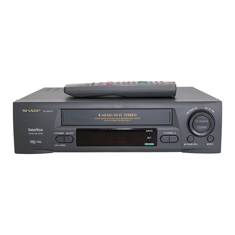
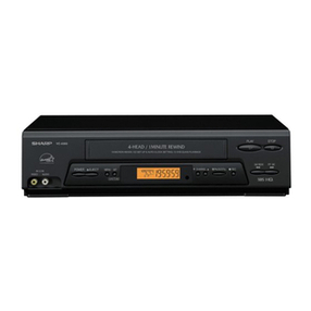
Sharp VC-H9888U User manual

VC-H9888U
1
VIDEO CASSETTE RECORDER
In the interests of user-safety (Required by safety regulations in some
countries) the set should be restored to its original condition and only parts
identical to those specified should be used.
SERVICEMANUAL
CONTENTS
VC-H9888UMODEL
Page
1. GENERAL INFORMATION .............................. 5
1-1 FEATURES.................................................5
1-2 SPECIFICATIONS ..................................... 5
1-3 LOCATION OF MAJOR COMPONENTS
AND CONTROL ......................................... 6
2. DISASSEMBLY AND REASSEMBLY .............. 7
2-1 DISASSEMBLY OF MAJOR BLOCKS....... 7
2-2 CARES WHEN REASSEMBLING.............. 8
Page
3. ELECTRICAL ADJUSTMENT .......................... 9
4. TROUBLESHOOTING .................................. 12
5. BLOCK DIAGRAM ..........................................22
6. CIRCUIT DIAGRAM AND PWB FOIL
PATTERN .......................................................32
7. REPLACEMENT PARTS LIST ....................... 45
8. EXPLODED VIEWS ....................................... 55
9. PACKING OF THE SET ................................. 59
This document has been published to be used for
after sales service only.
The contents are subject to change without notice.
SHARP CORPORATION
SX8Z5VCH9888U

VC-H9888U
2
part.Anyreadingof0.45Vrms(thiscorrespondsto0.3mArms
AC.) or more is excessive and indicates a potential shock
hazard which must be corrected before returning the video
cassette recorder to the owner.
IMPORTANT SERVICE NOTES
WARNING : TO REDUCE THE RISK OF FIRE OR ELEC-
TRIC SHOCK, DO NOT EXPOSE THIS AP-
PLIANCE TO RAIN OR MOISTURE.
RISK OF ELECTRIC SHOCK
DO NOT OPEN
CAUTION
CAUTION: TO REDUCE THE RISK OF ELECTRIC SHOCK. DO NOT
REMOVE COVER. NO USER-SERVICEABLE PARTS IN-
SIDE. REFER SERVICING TO QUALIFIED SERVICE PER-
SONNEL.
This symbol warns the user of uninsulated voltage
withintheunitthatcancausedangerouselectricshocks.
This symbol alerts the user that there are important
operatingandmaintenanceinstructionsintheliterature
accompanying this unit.
This symbol mark means fast operating fuse.
For continued protection against risk of fire, replace
only with same type fuse F901 (1.6A, 125V).
CAUTION:
BEFORE RETURNING THE VIDEO CASSETTE
RECORDER
Before returning the video cassette recorder to the user, perform
the following safety checks.
1. Inspectallleaddresstomakecertainthatleadsarenotpinched
or that hardware is not lodged between the chassis and other
metal parts in the video cassette recorder.
2. Inspect all protective devices such as non-metallic control
knobs, insulation materials, cabinet backs, adjustment and
compartment covers or shields, isolation resistor/capacitor
networks, mechanical insulators etc.
3. Tobe sure that no shock hazard exists, check for current in the
following manner.
●Plug the AC line cord directly into a 120 volt AC outlet (Do not
use an isolation transformer for this test).
●Using two clip leads, connect a 1.5k ohm, 10 watt resistor
paralleled by a 0.15µF capacitor in series with all exposed
metalcabinet partsanda knownearthground,such asawater
pipe or conduit.
●Use an SSVM or VOM with 1000 ohm per volt, or higher,
sensitivity or measure the AC voltage drop across the resisor
(See Diagram).
●Move the resistor connection to earth exposed metal part
having a return path to the chassis (antenna, metal cabinet,
screw heads, knobs and control shafts, etc.) and measure the
AC voltage drop across the resistor. Reverse the AC plug on
thesetandrepeatACvoltagemeasurementsforeachexposed
SSVM
AC SCALE
1.5k ohms.
10W
CONNECT TO
KNOWN EARTH
GROUND
TO EXPOSED
METAL PARTS
0.15 µF
TEST PROBE
1.6A 125V

VC-H9888U
3
entrelarésistance.InverserlaficheCA(uneficheintermédiaire
non polarisée doit être utilisée à seule fin de faire ces
vérifications.) sur l’appareil et répéter les mesures de tension
CA pour chaque piéce métallique exposée. Toute lecture de
0,45 Vrms (ceci correspond à 0,3 mArms CA) ou plus est
excessive et signale un danger de choc qui doit être corrigé
avant de rendre le magnétoscope à son utilisateur.
NOTES DE SERVICE IMPORTANTES
ATTENTION: POUR REDUIRE LES RESQUES D'IN-
CENDIE OU DE CHOC ELECTRIQUE,
NE PAS EXPOSER CET APPAREIL A
LA PLUIE OU A L'HUMIDITE.
AVANT DE RENDRE LE MAGNETOSCOPE
Avant de rendre le magnétoscope à l’utilisateur, effectuer les
vérifications de sécurité suivantes.
1. Vérifiertoutes les gaines defil pour êtresûr que les filsne sont
paspincés ou que le matériel n’est pas coincéentre le châssis
et les autres pièces métalliques dans le magnétoscope.
2. Vérifiertouslesdispositifsdeprotectiontelsquelesboutonsde
commande non métalliques, les matériaux d’isolement, le dos
ducoffret,lescouverclesdecompartimentetajustementoules
boucliers,lesréseauxderésistance/condensateurd’isolement,
Ies isolateurs mécaniques, etc.
3. Pourêtresûrqu’iln’yaaucunrisquedechocélectrique,vérifier
le courant de fuite de la maniére suivante.
●Brancher le cordon d’alimentation secteur directement dans
une prise de courant de 120 volts. (Ne pas utiliser de
transformateur d’isolement pour cet essai).
●Utiliser deux fils à pinces et connecter une résistance de 10
watts 1,5 kohm en parallèle avec un condensateur de 0,15 µF
ensérieavecdespiècesducoffretmétalliqueexposéesetune
masse de terre connue telle qu’un tuyau ou un conduit d’eau.
●Utiliser un VTVM ou VOM avec une sensibilité de 1000 ohms
par volt ou plus ou mesurer la chute de tension CA entre la
résistance (voir diagramme).
●Déposer la connexion de la résistance à toutes les pièces
métalliques exposées ayant un parcours de retour au châssis
(connexionsd’antenne,coffretmétallique,tétesdevis,boutons
etarbresdecommande,etc.)etmesurerlachutedetensionCA
RISQUE DE CHOC ELECTRIQUE
NE PAS OUVRIR
ATTENTION
Ce symbole avertit l'utilisateur que des instructions
importantesrelativesàl'utilisationetàl'entretiensetrouvent
dans le manuel accompagnant l'appareil.
ATTENTION: AFINDEREDUIRELESRISQUESDECHOCELECTRI-
QUE, NE PAS RETIRER LE COUVERCLE, AUCUN
ORGANE INTERNE NE PEUT ETRE REPARE PAR
L'UTILISATEUR. CONFIER L'APPAREIL A UN
DEPANNEUR QUALIFIE.
Ce symbole signale à l'utilisateur la présence d'une
tensionnonisoléeàl'intérieurdel'appareilquipeutêtrela
cause de secousses électriques dangereuses.
PRECAUTION:
Cette marque indique le fusible à action in stantansée.
Pourlaprotectioncontinuecontrelerisqued'incendie,ne
remplacer que par le fusible type F901 (1,6A, 125V).
0,15 µF
SONDE D'ESSAI
VERS PIECES
METALLIQUES
EXPOSEES
VTVM
ECHELLE CA
1.5 KOHMS
10W
CANNECTER A
UNE MASSE DE
TERRE CONNUE
1,6A 125V
VC-H9888U
4
PRECAUTIONS IN PART REPLACEMENT
When servicing the unit with power on, be careful to the section marked white all over.
This is the primary power circuit which is live.
Whenchecking thesoldering sideinthe tapetravel mode,makesure firstthat thetapehas beenloaded andthenturn
over the PWB with due care to the primary power circuit.
Makereadjustment,ifneededafterreplacementofpart,withthemechanismanditsPWBinpositioninthemainframe.
(1) Start and end sensors: Q701 and Q702
Insert the sensor’s projection deep into the upper hole of the holder. Referring to the PWB, fix the sensors tight
enough.
(2) Photocoupler: IC901
Refer to the symbol on the PWB and the anode marking of the part.
(3) Cam switches A and B: D708 and D709.
Adjust the notch of the part to the white marker of the symbol on the PWB. Do not allow any looseness.
(4) Take-up and supply sensors: D707 and D706.
Be careful not to confuse the setting direction of the parts in reference to the symbols on the PWB. Do not allow
any losseness.

VC-H9888U
5
1. GENERAL INFORMATION
1-1 FEATURES
• Hi-Fi Stereo Sound
• Built-in MTS (Multi-channel TV Sound) Decoder
• The VCR Plus+ Programming System / Cable Box Channel
Control Function / Digital Satellite Receiver Control Fundtion
• 360 Times Rewind Speed to Fast Forward and Rewind
• EZ Set up
• Double-Azimuth 4 Head
•19µClear Picture System (in EP mode)
• Auto VIEWCAM Dubbing Function
• HQ System for Better Resolution and color Reproduction
• Multi-Language(English/Spanish/French)OSD(OnScreen
Display) with Menu Screen Guidance
• 181-channelPLLQuartzSynthesizedRandomAccessTuner
with Automatic Channel Setting
• Quick Start with Full Loading Mechanism
• 1-Year, 8-Event Programmable Timer
• Simple Recording Timer
• Ruminus Universal Remote Control
• Gamma Function
• Sharp Super Picture
• Field-Still / Variable Slow / Frame Advance
1-2 SPECIFICATIONS
1) Recording system Format: VHS NTSC standard
Luminance signal: FM recording
Chroma signal: Low frequency converted direct recording
Color system: NTSC
Number of video head: 4
Tape speed: SP (33.35mm/sec.)
LP (16.67mm/sec.) (playback only)
EP (11.12mm/sec.)
2) Video signal Input level: 0.5 ~ 2.0Vp-p, 75 ohm Unbalanced
Output level: 1.0Vp-p, 75 ohm Unbalanced
Horizontal resolution: 220 lines (SP mode)
Signal to noise ratio: 45dB (SP mode)
3) Audio signal Input level: –8dBs (309mVrms, 47k ohm)
Output level: –8dBs (309mVrms, 1k ohm)
Frequency response: 80Hz ~ 10kHz (SP mode linear), 20Hz ~ 20kHz (Hi-Fi mode)
Signal to noise ratio: 43dB (SP mode linear)
Hi-Fi Dynamic range: 90dB (Hi-Fi models)
Wow and flutter: 0.005% max. (Hi-Fi mode) with T-120 tape
4) Receiving channel VHF: Channels 2 ~ 13
UHF: Channels 14 ~ 69
CATV: Channels A-8, A-5 ~ W+84
Antenna input Impedance: VHF/UHF; 75 ohm
5) Misc. Fast forward/Rewind time: Approximate 1.0 minutes with T-120 cassette
Power source: 120V, 60Hz
Power consumption: 20W
: 4W (When POWER is OFF)
: 0.6W (When Energy Saving is ON and POWER is OFF)
Allowable ambient temperature: 5°C to 40°C (41°F to 104°F)
Operating humidity: below 80% RH
Dimensions: 430 (W), 284 (D), 92 (H) mm (16-15/16, 11-6/32, 3-5/8 inch)
Weight: 3.5kg (7.7 lbs)
Accessories included: 75 ohm coaxial cable, Operation manual, Operation guide,
infrared remote control, Battery (2 pcs.)
Note: Specifications may be changed for improvement without notice.
• Real-Time Counter
• Automatic Daylight Saving-Time (D.S.T) Adjustment
• Blue Screen Noise Elimination
• Energy Saving Function
• Auto Tracking Control System
• Digital Program Search System (DPSS)
• Skip Search
• Instant Replay
• Auto Zero Back
• Recroded Section Auto Repeat
• Full Automatic Playback
• Tamper Proof
• Up to 8 Hours of Recording and Playback (with T-160
Cassette)
• Built-in Shuttle Control System
• Built-in Front AV Jacks
• Automatic Head Cleaning System
• 20 seconds Timer Back-up

VC-H9888U
6
1-3 LOCATION OF MAJOR COMPONENTS AND CONTROL

VC-H9888U
7
B
A
B
A
C
D
D1
D1
SHARP
C
Front AV PWB
Jack PWB
Front Panel
Operation PWB
Mechanism
Chassis
Top Cabinet
Main PWB
1
1
2
2
10
11
7
6
8
9c
9
3
3
Antenna
Terminal
5
5
f
13
b
e
d
a
g
D
TOP CABINET : Remove 4 screws 1.
FRONT PANEL : Remove 2 screws 2and 7 clips 3.
Becarefulnottoundothelowerhooks
alone andattempt to tilt the front panel
outof position. The jack PWBholder's
right-hand hook may get broken.
Undothefrontpanel'supperandlower
hooks together and take out the front
panel untilted.
OPERATION PWB
: Remove 1 clip a.
FRONT AV PWB/
: Remove 2 screws 5and 2 clip b.
JACK PWB/
JACK PWB HOLDER
MECHANISM / : Undothe 3 hooks each ofthefront left-
hand and right-hand PWB holders d
and e. Remove the 2 screws qand
9each first and then the 2 screws
6. Undo the hooks fand c. (Take
themechanism,thePWBs,andthe an-
tenna terminal board in this order out
of the chassis.)
ANTENNA : Remove 1 screw 8and shield case
g(Top). Remove 1 screw 7.
MAIN PWB : Remove 1 screw e.
CASSETTE : Removing the cassette control from
mechanism, remove 2 screws 0.
MAIN PWB UNIT/
ANTENNA
TERMINAL
COVER
2. DISASSEMBLY AND REASSEMBLY
2-1. DISASSEMBLY OF MAJOR BLOCKS
TERMINAL
COVER

VC-H9888U
8
INSTALLING THE CASSETTE CONTROLLER
When the cassette controller is installed on the mecha-
nism, the initial setting is essential condition.
There are two initial setting methods, namely electrical
and mechanical.
1. Electrical initial setting
So as to perform initial setting of mechanism execute the
Step1ofInstallationofcassettehousing.Afterascertain-
ing the return to the initial setting position (*1) install the
cassette controller. (Conditions: When mechanism and
PWB have been installed)
2. Mechanical initial setting
Feed the pulley feed gear of loading motor with screw
driver. After ascertaining the return to the initial set
position(*1) installthe cassettecontroller inthe specified
position.(Thismethodisappliedonlyforthemechanism.)
INSTALLING THE MECHANISM ON PWB
Lower vertically the mechanism, paying attention to the
mechanism edge, and install the mechanism with due
care so that the parts are not damaged. So as to fix the
mechanismtothemainPWBinstalltwohousings.(Fitthe
antenna cover to one of them. For other, fix the vicinity of
loading motor and solder joint side of main PWB.) Con-
nect again the FFC cable (AA-MH, AD-ME, AH-MZ)
between the mechanism and the main PWB.
Pulley feed gear
Screwdriver
Tilt mark (*1)
Casecon
drive gear
Drive angle of
cassette control
PARTS WHICH NEED PARTICULAR CARE
Wheninstallingthe mechanismchassis onthe PWBunit,
take care so as to prevent deformation due to contact of
mechanism chassis with REC TIP SW.
AL CONNECTOR
START SENSOR
REC TIP SWITCH
AE CONNECTOR
END SENSOR
AC CONNECTOR
2-2. CARES WHEN REASSEMBLING

VC-H9888U
9
3. ELECTRICAL ADJUSTMENT
Notes:
• Before the adjustment:
Electrical adjustments discussed here are often required after replacement of electronic components and
mechanical parts such as video heads.
Checkthatthemechanismandallelectriccomponentsareingoodworkingconditionpriortotheadjustments,otherwise
adjustments can not be completed.
• Theservocircuit adjustment data is written on the memory IC (IC710) that is used in this product. When this IC has
been replaced, it is necessary to readjust the servo circuit data.
• Before readjusting this data, warm up and age the set for more than 5 minutes.
• Instruments required:
• Color TV monitor • Dual-trace oscilloscope
• Alignment tape (VROATSV, VROABZGS) • Valve voltmeter (2-channel type)
• TV signal generator • Sound multiplex signal generator
• Blank video cassette tape • Screwdriver for adjustment
• Test point layout
Figure 3-1
TP202
TP802

VC-H9888U
10
Measuring
instrument
Mode
Cassette
Test point
Adjusting
point
Specification
Dual-trace oscilloscope
Playback
Alignment tape (VROABZGS)
TP202 (H.SW.P)
VIDEO OUT jack
Call up the test mode (get TP802
short-circuited). Usethe tracking/
channel select (') and (") buttons
of the set.
5.5±0.5H (lines)
SERVO CIRCUIT ADJUSTMENT
3-1 ADJUSTMENT OF HEAD SWITCHING
POINT
1. Play the alignment tape (VROABZGS).
2. ConnecttheoscilloscopetoTP202(CH-1)andVIDEO
OUTjack (CH-2).
3. GetTP802 onthemain PWBshort-circuitedto call the
test mode.
4. Press the PLAY button, and the play icon starts flash-
ing in the display and the automatic adjustment func-
tion gets started.
5. Wait until the play icon in the display stays on to
indicate that the adjustment is complete.
6. Watch the oscilloscope screen and make sure the
setting is 5.5 ±0.5 H.
7. Ifthesettingisoutofthisrange,readjustthedatausing
thechannelselect(')and(")buttonsofthesetorthe
remote controller.
8. Finally press the STOP button to quit the test mode.
Figure 3-2.
3-2 ADJUSTMENT OF SLOW TRACKING
PRESET
Measuring
instrument
Mode
Input signal
Test point
Adjusting
point
Specification
Color TV monitor
Makerecordingonself-recordingtape
inSPmodeorEPmode.Playitback.
Commercial broadcast or video sig-
nal
Color TV monitor
Call up the test mode (get TP802
short-circuited).UsetheTRACKING/
CHANNEL select (') and (") but-
tons of the set.
Sweep the noise bar down to the
bottom of the colormonitor screen.
1. Input commercial broadcast or video signal to video
input terminal.
2. Make recording on self-recording tape in SP mode.
Play it back.
3. Pressthe SLOW button andputthe unit in slowmode.
4. In the slow mode, get TP802 on the main PWB short-
circuited. Make sure all the display marks light up and
the test mode is called up.
5. Watchingthecolormonitor screen,pressthe tracking/
channel select (') and (") buttons. Sweep the noise
bar down to the bottom of the color monitorscreen.
6. Press the PLAY button to bring back the play mode.
Thenpress thePAUSE/STILL button tocall up thestill
playmode.Nowmakesurethereisnonoisebaronthe
screen.
7. For the EP mode put adjustment at the same adjust-
ment way as SP mode.
3-3. ADJUSTMENT OF FV (False Vertical
Sync) OF STILL PICTURE
Measuring
instrument
Mode
Input signal
Test point
Adjusting
point
Specification
Color TV monitor
Make recording on self-recording
tape in SP mode or EP mode. Play it
back.
Commercial broadcast or video sig-
nal
Color TV monitor
TRACKING/CHANNEL select (')
and (") buttons of the set.
No vertical jitter of picture
5.5±0.5H (lines)
CH-1
HEAD
SWITCHING
PULSE
CH-2
VIDEO OUT
CH-1: 1V/dev 50µsec/dev
CH-2: 2V/dev 50µsec/dev
V-sync.

VC-H9888U
11
1. Input commercial broadcast or video signal to video
input terminal.
2. Make recording on self-recording tape in SP mode.
Play it back.
3. Press the PAUSE/STILL button to freeze the picture.
4. Look at the monitor screen and adjust (') or (")
TRACKING/CHANNEL select buttons so that the ver-
tical jitter of the picture is minimized.
5. For the EP mode put adjustment at the same adjust-
ment way as SP mode.
3-4. ADJUSTMENT OF MULTIPLEX
SEPARATION
Measuring
instrument
Mode
Input signal
Test point
Adjusting
point
Specification
TV signal generator, Sound multi-
plexsignalgeneratorandValvevolt-
meter (2-channel type)
E-E mode
Sound multiplex signal
Audio output terminal (L, R)
R141 (S-IF ADJ.)
Maximumdifferenceinvalvevoltme-
ter pointer readings(over 25 dB).
1. Using the TV signal generator or the sound multiplex
signalgenerator,feedthesoundmultiplexsignaltothe
set's antenna terminal.
2. Set the sound multiplex signal generator to the stereo
mode. Give the left and right channels 400 Hz, 100%
modulation and 400 Hz, 0% modulation, respectively.
3. Connect the valve voltmeter's CH-1 and CH-2 to the
left-channel and right-channel audio output jacks, re-
spectively. Adjust R141 (S-IF ADJ.) so that the valve
voltmeter's pointer readings between both the chan-
nels be maximum (over 25 dB).

VC-H9888U
12
FLOW CHART NO.1 POWER TROUBLESHOOTING(1)
No power
Unplug the AC power cord. Replug it a few
seconds later.
YES
YES
YES
YES
NO
NO
NO
NO
NO
Is the fuse good?
Is AT 5V voltage line normal?
Check the secondary rectifier circuits.
Check the error voltage detection circuit
(Q705 and Q706).
Is "H" level applied at pin(1) of IC701?
Check the primary circuit parts for leakage or
short-circuit. (L901, D921 thru D924, D912,
T901, C904, IC903, D904, D913, D910, C908,
C918, etc.)
Replace the fuse. If it blows out again, go to
FLOW CHART NO.2 (Fuse blows out).
Are STBY 40V, STBY 23V, STBY 12V, STBY
5V, STBY -28V and filament voltage lines
normal?
FLOW CHART NO.2 POWER TROUBLESHOOTING(2)
In case of fuse blown out.
Check primary circuit forshort-circuit or leak.
(L901, D921-4, D912, T901, C904, IC903, D
904, D913, D910,C908, C918, etc.)
Check the secondary rectifier circuits and
rectifier diodes for short-circuit. (D905 thru
D909, D918, etc.)
Case (1) Case (2)
4. TROUBLESHOOTING
FLOW CHART NO.3 POWER TROUBLESHOOTING(3)
In case of abnormal noise(sound)
Check the secondary rectifier circuits and rectifier diodes for short-circuit. (D905 thru D909, D914,
D916 thru D918, Q902 thru 903, IC904, etc.)
FLOW CHART NO.5 TIMER TROUBLESHOOTING (1)
The flourescent display tube fails light up.
Is the supply voltage of 5V fed to pin(18) of IC801? Check STBY 5V line.
Is the supply negative voltage of -24V fed to pin(16)
of IC801? Check STBY -24V line.
Is there 4MHz oscillation at pins(19) and (20) of
IC801? Check FL801 and IC801.
Do IC701, IC801, a well as the KEY FIP DATA, FIP
CLOCK and FIP CS signal lines function? Check or replace the IC701 and IC801.
Check the fluorescent display tube and its periph-
erals. Check for cracks on the fluorescent
display tube.
YES
YES
YES
YES
YES
NO
NO
NO
NO
NO
Is the filament voltage applied between (1) and (2)
and (61)/(62) of the fluorescent display tube? Check power circuit and D952.
NO
YES
YES
NO
NO
FLOW CHART NO.3 POWER TROUBLESHOOTING(4)
Output voltage fluctuates too much.
Check the circuit and replace the defective
parts.
Check the circuit and replace the defective
parts. (IC901, IC903, D904, D913, D910,
D901, D903,R908, R912, R906, R907,
C908, C918, C910, C907, T901, etc.)
Replace IC901.
Does the secondary photocoupler circuit
function?
Does the primary photocoupler circuit
function?

VC-H9888U
13
FLOW CHART NO.6 TIMER TROUBLESHOOTING (2)
Are the key switches installed correctly and functioning?
Are the input voltages at pins (8) and
(9) of IC701 as specified?
Check the key switches connected with
pins (8) and (9) of IC701 and their peri-
pheral circuits.
Check peripheralcircuits of IC701.
YES (with shuttle switch)
YES
Replace IC701.
YES
Check AT 5V line.
YES
Check back-up circuit (Q704 thru 705).
NO
NO
NO NO
YES YES
Are the input voltages at pins (88) and
(87) of IC701 as specified? (KEY 1/2)
Key-in operation does not function.
YES (with tact keys)
Are the voltages at pins (8) and (9) of IC701 5V?
Check the key switches connected with
pins (88) and (87) of IC701 and their peri-
pheral circuits.
Is the cassette housing distorted? Fix or replace the cassette housing.
NO
YES
YES
YES
YES
NO
YES
NO
YES
FLOW CHART NO.8 CASSETTE CONTROL TROUBLESHOOTING(1)
A cassette tape is not take in.
NO
NO
NO
Check start sensor cover.
Check line between start sensor and pin(79)
of IC701
Check line between pin(93) of IC701 and pin
(2) of IC705.
Check IC705.
Check line between IC705 and loading motor.
Replace loading motor.
Is the specified voltage ( about 10V)applied at
the loading motor terminal when the cassette
tape is inserted?
Does pin(5) of IC705 change to about 10V
when the cassette tape in inserted?
Does pin(2) of IC705 go to a "H" level (about
1.7V) when the cassette tape is inserted?
Does pin(79) of IC701 change from"H" to "L"
level when the cassette tape is inserted?
Does the start sensor cover go to open when
the cassette tape is inserted?
NO
NO
NO
FLOW CHART NO.9 CASSETTE CONTROL TROUBLESHOOTING(2)
A cassette tape is taken in, but ejected at once.
Does the start sensor pulse at pin(79) of
IC701 change from "L" to "H" level when the
cassette tape is loaded?
Check line between start sensor and pin(79)
of IC701.
Does the end sensor pulse at pin(85) of
IC701 change from "L" to "H" level when the
cassette tape is loaded?
Check line between end sensor and pin(85)
of IC701.
Does the master cam mode shifter operate
normally when the cassette tape is loaded? Check line between cam switchs (A)/(B) and
pins (7)/(6) of IC701.
Replace IC701.
YES
YES
YES
FLOW CHART NO.7 INFRARED R/C TROUBLESHOOTING
No operation is possible from the infrared remote control.
Does the infrared remote control function? Replace infrared remote control
as required.
Is the supply voltage of 5V fed to C813 of (+) side? Check AT 5V and GND lines.
Is "L" pulse sent out from pin(1) of the receiver when
the infrared remote control is activated? Replace receiver.
Check between at pin(1) of receiver and all the way
up thru to pin(5) of IC701. Replace IC701.
YES
NO
YES NO
NO
NO
YES

VC-H9888U
14
FLOW CHART NO.10 LOADING MOTOR AND EJECT TROUBLESHOOTING
The cassette tape fails to come out.
Does the capstan motor start when the EJECT
button is pressed?
See FLOW CHART NO.12 CAPSTAN
MOTOR TROUBLESHOOTING
Does the take-up reel disk turn when the capstan
motor is running? Check reel disk and reel drive
unit.
With the take-up reel disk running, is the reel
pulse signal being fed to pin (2) of IC701?
Check line between pin(2) of IC701
and take-up reel sensor.
Is the voltage about 10V sent out from pin(7) of
IC705? Check IC705.
Is the specified voltage applied at the loading
motor terminal? Check line between IC705 and
loading motor.
Does the loading motor run? Replace loading motor.
Replace cassette cam, gear, etc.
YES
YES
YES
YES
YES
YES
NO
NO
NO
Is the pin (4) of IC705 at "H" level(about 1.7V)
when the reel pulsesignal is inputted?
Check pin(92) of IC701.
YES
NO
NO
NO
NO
YES
YES
NO
NO
NO
FLOW CHART NO.11 SYSTEM CONTROL TROUBLESHOOTING
No power is turned on.
Does power control (H) signal at pin(94) of
IC701 change from "L" to "H" level? Check IC701.
Does the base voltage of Q951 change from
about 5.0V to 4.5V? Check line between Q952 and pin(94) of
IC701.
Is voltage of 5.0V sent out from the emitter of
Q951? Check Q951 and STBY 15V line.
FLOW CHART NO.12 CAPSTAN MOTOR TROUBLESHOOTING
The capstan motor fails to run.
Is the voltage more than about 2.6V DC
given out of pin(32) of IC701? Check IC701.
NO
NO
NO
NO
NO
YES
YES
YES
YES
Is the supply voltage of 5V fed to pin(8) of
AC connector? Check PC 5V line.
Is the voltage more than 2.6V DC sent in
pin(4) of AC connector? Check line between the AC connector and pin
(32) of IC701?
Is the voltage of pin(3) of AC connector 1.6
~2.7V? Check pin(60) of IC701.
Is 12V voltage fed to pin (5) of AC
connector?
YES
Replace capstan motor.
Check the capstan power supply circuit .
(in normal mode)
Check D957 and the STBY 12V line.
(in high-speed FF/REW mode).
Check Q955 thru Q958, D962 thru
D967 and the STBY 23V line.
FLOW CHART NO.13 DRUM MOTOR TROUBLESHOOTING(1)
The drum motor fails to run.
Is the voltage more than about 2.6V DC fed to
pin(31) of IC701? Check IC701.
NO
NO
YES
Is the voltage more than about 2.6V DC fed to
pin(7) of AD connector? Check line between pin(7) of AD connector
and pin(31) of IC701.
NO
YES
YES
Is the voltage of 12V fed to pin(4) of AD
connector?
Replace drum motor.
Check STBY 12V line.

VC-H9888U
15
FLOW CHART NO.14 DRUM MOTOR TROUBLESHOOTING(2)
The drum motor runs only for a few seconds.
Is drum PG signal fed to pin(5) of AD
connector?
Is drum PG signal fed to pin(66) of IC701? Check line between pin(5) of AD
connector and pin(66) of IC701.
Is head switching pulse sent out from the
pin(23) of IC701? Check IC701.
Replace IC701.
Check drum motor.
YES
YES
YES
NO
NO
NO
D-FG
about 5Vp-p
D-PG
about 5Vp-p
YES
NO
YES
YES
NO
NO
FLOW CHART NO.15 HEAD SWITCHING PULSE TROUBLESHOOTING.
No head switching pulse.
See FLOW CHART NO.13, 14
(DRUM MOTOR
TROUBLESHOOTING(1), (2))
Is the drum motor rotating?
Is the drum PG signal and drum FG signal
properlypresent on pins(66) and (65) of
IC701, respectively? Replace IC701.
Check line between pins(3) and (5) of AD c
onnector and pins(66) and (65).
Check line between AD-ME harness and
drum motor.
Are there drum PG and FG signals at pins
(3) and (5) of IC701, respectively?
Check peripheral circuit of X701.
NO
YES (In PB mode) YES (In PB mode)
Is there drum FG signal at pin(65) of IC701
present? Is the V-SYNC signal(reference) at pin(50) of
IC701?
YES
YES NONO
Check peripheral circuit of C770 - C771
and R770.
Check drum FG signal line.
Is the head switching pulse at pin(23) of IC701
present?
NO
See FLOW CHART NO.15
(HEAD SWITCHING PULSE
TROUBLESHOOTING.)
YES
Is there drum error signal at pin (33) of IC701?
NO
Replace IC701.
YES
Is the drum control voltage applied to pin(7)
of AD connector? Is pin(31) of IC701 in high impedance?
NO
NO
Is there 14.3MHz oscillation at pins(37) and (38) of IC701?
YES
Check the harness between AD connector
and ME connector. Replace drum motor.
NO
FLOW CHART NO.16 DRUM SERVO TROUBLESHOOTING
Drum servo does not function.

VC-H9888U
16
12
FLOW CHART NO.17 CAPSTAN SERVO TROUBLESHOOTING
Capstan servo does not function.
Only PB mode inoperative Only REC mode inoperative
YES
NO
YES
NO
NO
NO
Check peripheral circuit
of C770, C771 and
R770.
Is there 14.3MHz
oscillation at pins(38)
and (37) of IC701?
Check peripheral circuit
of X701.
YES
Check capstan motor
unit and/or replace.
Is there capstan error
signal at pin(34) of
IC701?
Replace IC701.
Replace A/C head.
YES
YES
YES
NO
NO
NO
Is there capstan error
signal at pin (34) of
IC701?
YES
NO
Does pin(32) of IC701
operatenormally?
YES
NO
Is there REC CTL
signal output at pins
(74) and (75) of IC701?
Does PB CTL signal
appear at pin(76) of
IC701 (TP204)?
Does A/C head operate
normally?
Adjust the height of the
A/C head.
Does the capstan FG
signal appearat pin (67)
of IC701?
Check the capstan
FG signal line and
AC-MC harness.
Is video signal fed to
pin (50) of IC701?
Are REC and/or PB
mode inoperative?
YES
Replace AA-MHharness.
NO
Is AA-MH harness
normal?
YES
Check "1" (Only PB
mode inoperative)
Check "2" (Only REC
mode inoperative)
Replace IC701.
NO
NO
FLOW CHART NO.18 E-E MODE TROUBLESHOOTING
No picture E-E signal.
NO
NO
NO
NO
NO
YES
YES
Is there picture signal inputted in the pins
(28), (30) and (31) of IC201? 1For ext. input mode.
■Check line between rear video input terminal
(J202) and pin(30) of IC201.
■Check the line between front video input
terminal (J202) and pin (28) of IC201.
2For U/V tuner mode.
■Check line between pin (24) of U/V tuner and
pin (31) of IC201.
Is the supply voltage of 5V fed to pin(12) of IC201?
YES
YES
YES
Is there a picture signal outputted in the
emitter of Q273? Check clump circuit (Q273).
Is there serial data and clock signal applied to
pins(63) and (62) of IC201?
Check line between pins(63), (62) of IC201 and
pins(17), (18) of IC701.
Is the supply voltage of 5V fed to pin(51) of IC701?
NO
Check STBY 5V line.
YES
NO
Check peripheral circuit of Q251.
Is there video signal at the emitter of
video output buffer (Q251)?
YES
1Line output : Check the line between Q251 peripheral and output terminal periphery.
2RF output : Check the line between Q251 peripheral and pin (6) of tuner periphery.
Is there a picture signal outputted in the
pin(52) of IC201?
Is there a picture signal inputted in the
pin(49) of IC701?
Is there a picture signal outputted in the
pin(47) ofIC701?
Check line between pin(52) of IC201 and pin(49)
of IC701.
Check PC 5V line.
NO
YES
Is there a picture signal outputted in the
emitter of Q272? Check Q271, Q272 and Q274.
NO
YES
Is there a picture signal outputted in pin
(7) of IC406? Is pin (2) of IC406 "L" level ?
NO
Replace IC406.
NO
YES
Is there a picture signal outputted in the
emitter of Q261? Check line between pin (52) of IC201 and Q261,
and their peripheral parts.

VC-H9888U
17
FLOW CHART NO.19 RECORDING MODE TROUBLESHOOTING
Picture (Luminance) record is impossible (E-E mode is possible).
NO
NO
NO
NO
NO
YES
Is there luminance signal (approx. 0.5Vp-p)
input in the pin (19) of IC201? Check line between pins (18) and (19) of IC
201. (C206)
YES
Is there luminance signal (approx. 0.3Vp-p)
input in the pin (42) of IC201? Check line between pins (21) and (42) of
IC201 (C208).
YES
Is there luminance signal (approx. 0.5Vp-p)
input in the pin (23) of IC201? Check line between pins (24) and (23) of
IC201 (C210).
YES
Is there luminance signal (approx. 0.5Vp-p)
input and output in the pins (13) and (14) of
IC201, respectively?
Check peripheral circuit of pins (13) and (14)
of IC201 (R201,R202, C203).
YES YES
Is there luminance signal (approx. 0.5Vp-p)
input in the pin (26) of IC201? Check line between pins (39) and (26) of
IC201 (C212).
NO
Is there luminance signal (aprox. 0.5Vp-p)
output from the pin (39) of IC201?
YES
Is voltage 5V applied to the CCD section
power terminal at pin (36) of IC201?
Is CCD control voltage approx. 5V normally to
the pin (37) from pin (57) of IC201?
Is clock signal (approx. 7.16MHz/0.5Vp-p)
for CCD applied normally to the pin (44) from
(69) of IC201?
Although picture record is possible, colour does not appear
(E-E mode is possible).
NO
NO
NO
YES
YES
Is voltage of 5V applied to the chroma power
terminal at pin (61) of IC201?
Check peripheral circuit pin (61) of IC201 and
PC5V line.
Is there chroma signal
(approx. 143mVp-p/burst) input in the pin
(46) of IC201?
Check line between pins (60) and (46) of
IC201 (C512).
YES
Is there chroma signal (approx.180mVp-p
/burst) input in the pin (58) of IC201?
Check line between pins (58) and (35) of
IC201 (R505, C515).
YES
Check whether the pins(73) and (71) of IC201
oscillate 3.58NHz.
Is there chroma signal (approx. 180mVp-p
/burst) output from the pin (35) of IC201?
YES
NO
SP mode:
Is there record FM signal (approx. 20mVp-p) output in the pins (88), (89) <<SP1>> and pins (86), (87) <<SP2>>of IC201?
EP mode:
Is there chroma ingredient included signal (approx. 20mVp-p) output in the pins (93), (94) <<EP1>> and pins (92), (91) <<EP 2>> of IC201?
YES
Check or replace the cylinder.
NO
YES
Is the supply voltage of 5V (PRE/REV Vcc)
fed to pin (90) of IC201?
Replace IC201.

VC-H9888U
18
FLOW CHART NO.20 PLAYBACK MODE TROUBLESHOOTING
Playback picture does not appear (E-E mode is possible).
NO
YES
Is there FM signal (approx. 0.4Vp-p) input in
the pin (78) of IC201?
YES
Check line between pins (79) and (78) of
IC201.
YES
NO
Is there luminance signal (approx. 0.25Vp-p)
input and output in the pins (13), (14) and
(16) of IC201?
Check peripheral circuit of pins (13), (14) and
(16) of IC201.(C203, R202, R202, L201,
C205 and R203)
YES
NO
Is there luminance signal (approx. 0.5Vp-p)
at the pin (19) of IC201? Check line between pins (18) and (19) of
IC201 (C206).
YES
NO
Is there luminance signal (approx. 0.3Vp-p)
at the pin (42) of IC201? Check line between pins (21) and (24) of
IC201 (C208).
YES
NO
Is there luminance signal (approx. 0.5Vp-p)
at the pin (26) of IC201?
YES
NO
Is there luminance signal (approx. 0.5Vp-p)
at the pin (23) of IC201?
Check line between pins (39) and (26) of
IC201 (C212).
Is there luminance signal (approx. 0.4Vp-p)
output in the pin (79) of IC201?
NO
Is the supply V-H.SW.P signal fed to pin
(81) of IC201?
YES
Check V-H.SW.P line.
YES
Is there luminance signal (approx. 0.5Vp-p)
at the pin (39) of IC201?
NO
Although picture playback is possible, colour does not appear
in PAL or NTSC mode (E-E mode is possible).
NO
YES
Is voltage 5V applied to the chroma power
terminal at pin (61) of IC201?
YES
Check peripheral circuit of pins (61) of IC201
and PC5V line.
NO
Is there chroma signal (approx. 403mVp-p
/burst) at the pin (46) of IC201?
YES
NO
Is there chroma signal (approx. 508mVp-p
/ burst) at the pin (58) of IC201? Check line between pins (58) and (35) of
IC201 (R505, C515).
YES
YES
NO
Is there chroma signal (approx. 286mVp-p
/burst)output from the pin (55) of IC201?
Replace IC201.
Is there Chroma signal output at the emitter
of Q552?
Check line between pins (60) and (46) of
IC201 (C512).
YES
Check whether the pins(73) and (71) of
IC201 oscillate 3.58NHz.
Is there chroma signal (approx. 508mVp-p
/ burst) at the pin (35) of IC201?
NO
YES
Is voltage 5V applied to the CCD section power terminal at pin (36) of IC201?
Check line between pins (24) and (23) of
IC201 (C210).
Replace IC201.
Is CCD control voltage approx. 5V normally to the pin (37) from pin (57) of IC201?
Is clock signal (approx. 7.16MHz<0.5Vp-p) for CCD applied normally to the pin (44) from (69) of IC201?
NO
Check peripheral circuits of Q551 and Q552.
YES
NO
Is there luminance signal (approx. 0.5Vp-p)
at the pin (52) of IC201?
YES
NO
Is there luminance signal (approx. 0.5Vp-p)
at theemitter of Q261? Check peripheral circuits of Q261.
YES
NO
Is there luminance signal (approx. 0.5Vp-p)
at the pin (23) of IC201? Check GAMMA circuits.
NO
Is there luminance signal (approx. 0.5Vp-p)
at the pin (7) of IC406? Is pin (2) of IC406 at "H" level?
NO
Check line between pin (2) of IC406 andpin
(98) of IC701.

VC-H9888U
19
YES
YES
YES
YES
NO
NO
NO
NO
YES
NO
NO
NO
FLOW CHART NO.21 Hi-Fi SOUND MODE TROUBLESHOOTING(1)
Is there audio signal inputted at each input
terminal of IC651 as shown in table?
Tuner input terminal.
Front input terminal.
Rear input terminal.
L-ch R-ch
pin(63) pin(49)
pin(6) pin(44)
pin(61) pin(52)
Check front input terminal.
Check tuner and MTS decoder circuit
(IC161).
Check rear audio input terminal (J201).
Is the supply voltage of 5V fed to pin (62)
and 9V fed to pin(60) of IC651?
Check line between pin(8) of IC651 and
pin (21) of IC701.
Line output terminal : Is there audio signal outputted at pins(58) and (56) of IC651?
RF output terminal : Is there audio signal outputted at pin(57) of IC6301?
Line output terminal :
Check line ranging from pins(58) and (56) of IC651 to the audio output terminal.
RF output terminal :
Check line ranging from pin(57) of IC651 to the audio input terminal of tuner (pin(2) of TU101).
Check the regulator circuits of STBY 5V and
PC 9V.
Is there audio signal outputted at pins(5), (45)
of IC651?
Check line between pins(31, 32) of IC651
and pins(17,18) of IC701.
Check line between pins(4, 5) and (46, 45) of
IC651. (C651, C661)
Are there serial data and clock at pins (31)
and (32) of IC651?
Replace IC651.
Is pin(99) of IC201 "L" level?
No Hi-Fi E-E sound heard.
NO
YES
YES
YES
NO
NO
FLOW CHART NO.22 Hi-Fi SOUND MODE TROUBLESHOOTING(2)
Is there 600mVp-p recording FM signal (L-ch)
at the monitor terminal (pin (29) of IC651)?
Check BIAS CTL (L) line.
Check AH-MZ harness.
Is pin (33) of IC651 at the BIAS CTL (L) level?
Is there REC FM signal outputted to the
IC651 pins (26) to (22)(ch-1)/pins (26) to
(25)(ch-2) ?
NO
Check the record current setting resistor
R353 at pin (27) of IC651.
No Hi-Fi sound recording(E-E mode is possible)
Is there REC FM signal at pins (18) and (19)
of IC651? Replace IC651.
NO
YES
YES
YES
NO
NO
FLOW CHART NO.23 Hi-Fi SOUND MODE TROUBLESHOOTING(3)
Is there playback envelope signal (about
300mVp-p) outputted to the pins(18), (19) of
IC651?
Check the A-H.SW.P. signal line between
pin(35) of IC651 and pin(26) of IC701.
Replace IC651.
Replace IC651.
Is there A-H.SW.P. signal at pin( 35) of
IC651?
No Hi-Fi sound playback(E-E mode is possible)

VC-H9888U
20
NO
NO
NO
FLOW CHART NO.24 LINEAR SOUND MODE TROUBLESHOOTING (1)
Is the Audio signal inputted to pin (8) of
IC201?
Is there "L" level at pin (99) of IC201?
YES
YES
No linear sound recording (Hi-Fi E-E mode is possible)
Does the bias oscillation circuit function?
Check line between pin (53) of IC651 and
pin (8) of IC201.
Check R617
Check
bias oscillation circuit.
(T601, Q602, Q603, Q604)
YES
Is there audio signal superimposed with the
bias signal at pin (4) of IC201?
YES
Check the MH-AM harness and A/C head.
YES
NO
NO
NO
FLOW CHART NO.25 LINEAR SOUND MODE TROUBLESHOOTING (2)
YES
YES
Is theA/C Head Clean?
Is the azimuth hight of A/C head properly
adjusted?
Replace A/C head.
Is there a audio signal at pin(11) of IC201?
YES
Are the MH-AA harness and the PB AMP.
peripheral parts normal?
Readjust A/C Head hight.
YES
No linear sound playback (Hi-Fi E-E mode is possible)
Is there audio signal (PB EQ) at pin (100)
of IC201?
Is there "L" level at pin (99) of IC201?
Check line between pin (11) of IC201 and
pin (54) of IC651.
Check R617.
Replace IC201.
YES
YES
Table of contents
Other Sharp VCR System manuals

Sharp
Sharp VC-H818U User manual

Sharp
Sharp VC-A230X User manual

Sharp
Sharp VC-FH30FPM User manual

Sharp
Sharp VC-6300G User manual

Sharp
Sharp VC-A136X User manual

Sharp
Sharp VC-A220X User manual

Sharp
Sharp VC-A410X User manual

Sharp
Sharp VC-M333HM(S) User manual

Sharp
Sharp VC-TA350 User manual

Sharp
Sharp VC-FH70GM User manual

Sharp
Sharp VC-MH711GM User manual

Sharp
Sharp VC-H85X User manual

Sharp
Sharp VC-GH61SM User manual

Sharp
Sharp VC-A565U User manual

Sharp
Sharp VC-488NS User manual

Sharp
Sharp VC-MH71SM User manual

Sharp
Sharp DV-NC150U User manual

Sharp
Sharp VC-A592U User manual

Sharp
Sharp VC-S2000HM Quick start guide

Sharp
Sharp VC-H992U User manual