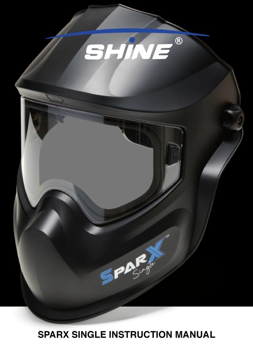
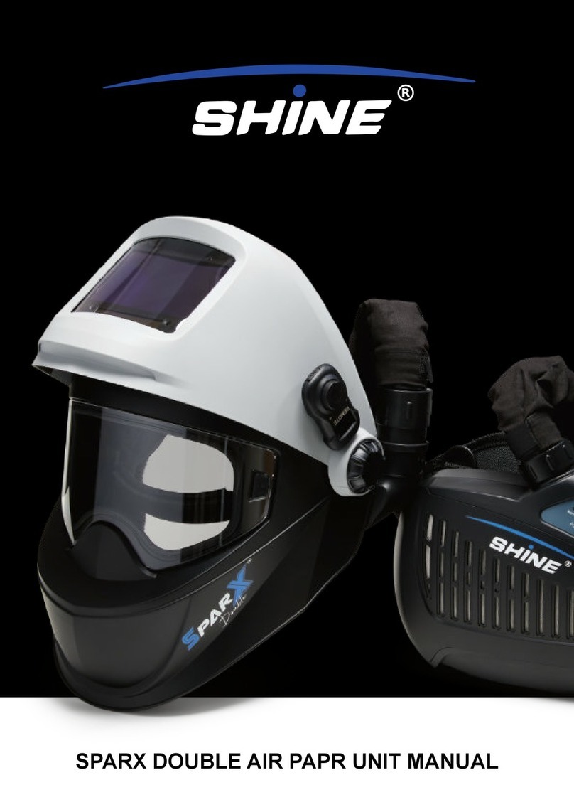
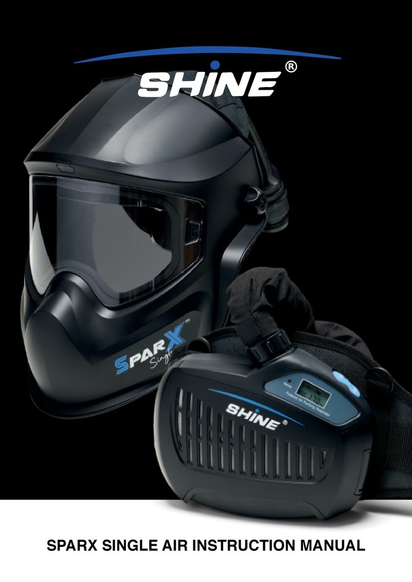
SHINE SPARX DOUBLE User manual

SPARX DOUBLE INSTRUCTION MANUAL

- English -
2 English
SparX Double
Professional Quality Auto-Darkening Helmet
WARNING Read and Understand All Instructions Before
Using the Equipment.
SAFETY WARNINGS
The auto-darkening helmet with improved High Denition Filter
Optics, delivers a new generation of face and eye protection.
Advanced integrated technology, such as LCD, optoelectronics
detection, solar power, and microelectronics are coordinated
to produce one of the safest, fastest and most reliable auto-
darkening helmets available. The auto-darkening helmet can
not only efciently protect operator’s eyes and face from sparks,
spatters, and harmful radiation under normal welding conditions,
but also make both hands free and strike arc accurately resulting
in increased efciency and improved quality welds. It may
be widely used for various welding, cutting, spraying and arc
gouging, etc.
• This auto-darkening helmet is not suitable for “overhead”
welding, laser welding or oxyacetylene welding
applications.
• This helmet will not protect against explosive devices or
corrosive liquids. Machine guards or eye splash
protection must be used when these hazards are
presented.
• Impact resistant, primary eye protection, spectacles or
goggles that meet current ANSI specications must be
worn at all times when using this welding helmet.
• Avoid work positions that could expose unprotected
areas of the body to spark, spatter, direct and/or
reected radiation. Use adequate protection if exposure
cannot be avoided.
• Do not make any modications to either the ADF
cartridge or helmet, other than those specied in this
manual.
• Do not use any replacement parts other than those
specied in this manual. Unauthorized modications
and replacement parts will void the warranty and
expose the user to the risk of personal inury.
• Do not immerse this helmet in water because this model
is not waterproof.
• Do not use any solvents on any ADF or helmet
components.
• The recommended operating temperature range for this
ADF cartridge is -10°C ~ 65°C (14°F ~ 149°F). Do not
use this device beyond these temperature limits.
Failure to follow these warnings and/or failure to follow all of the
operating instructions could result in severe personal injury.
CONTENTS
1. Operation instruction
2. Specications
3. LED ash explanation on ADF
4. Screen icon explanation on remote control
5. Mode setting
6. Variable shade control
7. Sensititivy control
8. Delay control
9. Grinding or cutting selection
10. Battery indicator
11. Power supply and charge battery
12. Remote control pair with ADF
13. Headgear adjustements
14. Replace inner visor
15. Replace outer protection lens
16. True color
17. Maintenance
18. Trouble shooting
19. Warranty
20. Part list
1. OPERATION INSTRUCTION
Before use
• Check for light tigthness and check the inside & outside
protection lens are clean and that no dirt is covering the
sensors on the front of the auto-darkening-lter (ADF)
cartridge.
• Make sure the protection lms on both inside & outside
protection lens are removed.
• Inspect all operating parts for signs of wear or damage.
Any scratched, cracked, or pitted parts should be
replaced immediately.
This ADF is fully controlled by a Remote control and connected
with Bluetooth. All the adjustement of the ADF is operated on the
Remote Control. ADF will change to the Function mode you set
by the Remote Control.

- English -
3English
2. STANDARDS
Specications of ADF (SparX)
1. CE Classication 1/1/1/1
2. True Color Yes
3. LCD viewing area 100 x 60 mm (3.94” x 3.28”)
4. Light State Shade DIN 4
5. Dark Variable Shades DIN 5-9 / 9-13
6. Switching Time (light to
dark)
0.08ms
7. Delay Time (dark to light) Adjustable (level 1-5 for 0.1-
0.9s)
8. Sensitivity Adjustable (level 1-5 for low-
high)
9. Arc Sensors 4
10. Grinding Function Yes
11. Cutting Function Yes, shade 5
12. Power Supply Solar cell and Li-ion rechar-
geable battery
13. ADF battery operating
time
>300h
14. Charging time 2.5h
15. Battery Life ≥ 500
16. Operating temperature -10°C ~ 65°C (14°F ~ 149°F)
17. Inside PC lens 104.5 x 64 x 1 mm
18. Outside PC lens 118 x 97 x 1 mm
19. Inner visor Clear Visor, DIN 1
20. Standards CE EN379, ANSI Z87.1, CSA
Z94.3, AS/NZS
21. Warranty 2 years
Specications of Remote
1. Display OLED
2. Power Supply Li-ion rechargeable battery
3. ADF battery operating time >300h
4. Charging Time 2.5h
5. Battery Life -10°C ~ 65°C (14°F ~ 149°F)
3. LED FLASH EXPLANATION ON ADF
There are 3 LEDs on the ADF showing the working status of the
ADF.
1. Running (green)
a. LED will ash once every 2 sec while paring with
Remote Conrol
b. After successfully paired, LED will ash when ADF
receives control signal from Remote Control
2. Grinding/Cutting (orange)
a. LED ash when ADF works in grinding/cutting mode
3. Low power/Charging (Red/Green)
a. LED will become red when ADF is out of power
b. LED will be green and will ash while charging
c. LED will be green and normally on when charging is
nished
The representation of the LEDs on the ADF:
4. SCREEN ICON EXPLANATION
5. MODE SETTING
• ADF has 4 function modes
1. Welding mode (shade range 5-9)
2. Welding mode (shade range 9-13)
3. Grinding mode
4. Cutting mode
• Long press the button (8) on the remote control for 2 sec
and release, the ADF mode will be changed circularly
during these 4 modes. LCD display will show the picture
from 1 to 4 circulation.
Picture 1 Picture 2
Picture 3 Picture 4

- English -
4 English
• At welding mode 3 functions can be adjusted
1. Sensitivity
2. Shade
3. Delay
• At welding mode, short-press the button on the remote
control less than 1 sec and release, the function will be
changed circularly during shade, sensitivity and delay
time.
6. VARIABLE SHADE CONTROL
If the shade is in the range 5-9 or range of 9-13, clockwise rotate
the button on the remote control, shade number will be increased;
or anticlockwise rotate the button on the remote control, shade
number will be reduced.
Note
• Choose an optimum shade number for the required
welding process or application (see table 1)
• If the ADF does not darken when striking arc, stop
welding immediately and contact our representative
7. SENSITIVITY CONTROL
The responsiveness to different light levels in various welding
processes can be adjusted in the range 1-5 (from low to high).
Senstivity can only be adjusted at welding mode.
• Short press the button (8) on the remote control and
select SENS and clockwise rotate the button on the
remote control, sensitivity will be increased; or
anticlockwise rotate the button on the remote control,
sensitivity will be reduced. After the icon 6 mentioned is
displayed on the screen, number can be changed
in the range of 1 to 5.
a. Turn to level 1 (low): The sensitivity changes to be
lower.
• Suitable for high amperage welding and
welding in bright light conditions (lamp light or
sun light).
b. Turn to level 5 (high): The sensitivity changes to be
higher.
• Suitable for low amperage welding and using
in poor light conditions.
• Suitable for using with steady arc process
such as TIG welding.
• Under normally use, a higher sensitivity
setting is recommended.
8. DELAY CONTROL
The length of time delay for the ADF returns to light state after
welding can be adjusted in the range 1-5 (for 0.1~0.9s). The time
delay is for protection of welder’s eyes from strong residual rays
after welding.
• Short press the button (8) on the remote control and
select DELAY and clockwise rotate the button on the
remote control, delay time will be increased; or
anticlockwise rotate the button on the remote control,
delay time will be reduced. After the icon 7 mentioned is
displayed on the screen, number will be changed in
the range of 1 to 5.
a. Turn to level 1 (0.1s): The time the ADF lighten after
welding to be shorter. The shortest time is about 0.1s
depending upon welding point temperature and
shade set. This setting is ideal for track welding or
production welding with short welds.
b. Turn to level 5 (0.9s): The time the ADF lighten after
welding to be longer. The longest time is about 0.9s
depending upon welding point temperature and
shade set. This setting is ideal for welding at high
amperage where there is an after-glow from the weld.
9. GRINDING SELECTION
Select grinding mode by pressing the button on the remote
control, picture 3 mentioned will show on the remote control and
the orange light on ADF will ash.
Note
• Do not weld in the grinding mode, the ADF will not
darken.
10. CUTTING SELECTION
Select cutting mode by long pressing the button on the remote
control for 2 sec and release, picture 4 will show on the remote
control and the orange light on ADF will ash.
Note
• Do not weld in the cutting mode.
11. BATTERY INDICATOR
Icon 1 mentioned indicates the remote control battery status.
Charge the battery when it is low, otherwise, the remote control
will be out of work.
Charge the battery of ADF when the light on ADF becomes
red. Otherwise, switching time will become slower and shade
accuracy will be compromised.
12. POWER SUPPLY AND CHARGING
The power of the auto-darkening helmet is provided by solar cells
and rechargeable lithium battery.
Charge battery with Micro-USB cable when battery is low (5&6)

- English -
5English
Picture 5 Picture 6
13. REMOTE CONTROL PAIR WITH ADF
ADF and remote control is paired one to one when assembel on
the helmet and do not need to be paired again. Icon 2 mentioned
will show . One remote control can only control one ADF
which has been paired.
A new remote control can be paired with a new ADF. Put the
new ADF and new remote control together. Long press the pair
button on the ADF (picture 7) with a ne needle for more than 3
sec and release. Then long press the pair button on the remote
control (picture 8) with a ne neelde for more than 3 sec and
release. Running LED on ADF will ash once every 2 sec and will
stop ashing when succesfully paired. The icon 2 mentioned will
show ; if icon 2 shows , it means failed pair and needs to be
paired again.
Picture 8Picture 7
13. HEADGEAR ADJUSTEMENTS
Because the shapes of heads vary from person to person, the
work positions and the observing angles are different. Operator
may adjust the headband in 5 parameters:
1. Select eye level by headband adjusting buttons (1)
2. Select view angle by segmental positioning plate (2)
3. Adjust head size perimeter by pushing and turning the
headband tightness adjusting knob (3)
4. Select eyes distance from ADF by adjusting headgear
screws to 1 of te 5 slots on the headgear slider (4).
Make sure both sides are equally positioned for proper
vision.
5. Select the height of the headgear by adjusting
the block washers (5) up or down on the block washer
adjustement (6).
14. REPLACE INNER VISOR
The large inner visor is a protection lens and must be replaced if
broken, damaged or covered with welding spatter to the extent
that vision is impaired.
• Flip up the outer cover
• Push the plugs inside the helmet up, see position 1.
The inner visor will be released from the helmet; pull
the inner visor out, see position 2.
• Insert the visor, it is necessary to locate the button
into the corresponding hole in the helmet, then push the
plugs inside the helmet down and lock the visor
• The user must always make sure the visor is tted
properly and is locked well and there are no visible
gaps.
Table of contents
Other SHINE Motorcycle Accessories manuals
