SHINE SPARX SINGLE User manual
SPARX SINGLE INSTRUCTION MANUAL

- English -
2 English
SparX Single
Professional Quality Grinding/Welding Helmet
WARNING Read and Understand All Instructions Before
Using the Equipment.
SAFETY WARNINGS
This helmet can only resist a certain amount of heat. Please do
not place hot electrode holders inside the helmet and please do
not place the helmet near naked ames or hot work surfaces.
Scratched or damaged visors and lenses must always be
replaced if broken, damaged or covered with spatter to the extent
that vision is impaired.
The user should conduct daily regular checks to ensure no
damage is evident. Materials that may get in contact with the
wearers skin could cause Allergic reactions to susceptible
individuals. Eye-protectors against high speed particles worn
over standard ophthalmic spectacles may transmit impacts, thus
creating a hazard to the wearer.
We recommend a use of the helmet and visors for a period of 5
years. The duration of use depends on various factors such as
use, cleaning storage and maintenance.
Please check regularly of the consumable components and
replace if serviceability or visibility is suspected to be affected, and
nally dispose when critical components not offered as spares
are suspected to be damaged or if serviceability is affected.
• This helmet is not suitable for laser welding.
• Never place this helmet on a hot surface.
• This helmet will not protect against explosive devices
or corrosive liquids.
• Do not make any modications to either the lens or
helmet, unless specied in this manual.
• Do not use replacement parts other than those speci
ed in this manual. Unauthorized modications and re
placement parts will void the warranty and expose the
operator to the risk of personal injury.
• Do not immerse the helmet in water.
• Do not use any solvents on the lter screen or helmet
components.
• Storing temperature: -20 °C ~ +85 °C (- 4 °F ~ +185
°F). The helmet should be stored in dry cool and dark
area, when not using it for a long time.
• Clean the lens surface regularly; do not use strong
cleaning solutions. Regularly replace the cracked/
scratched/pitted front lens.
CONTENTS
1. Instructions for use
2. Standards
3. Range of application
4. Preoperation and operation
5. Service and maintenance
6. Replacing the large visor
7. Replacing the outer ip visor
8. Part list and assembly
9. Shade calculation
10. Helmet marking explanation
1. INSTRUCTIONS FOR USE
Information manual for the Sparx Single welder protective helmets
comply with Paragraph 1.4 of Appendix II of the EC Regulations.
Sparx Single helmets offer permanent protection against UV/IR
rays, also face and eye protection from sparks caused by the
welding process.
Do not look directly at the welding rays with unprotected eyes
when the arc strikes. This can cause painful inammation of the
cornea and irreparable damage to the lens of the eye leading to
cataracts.
2. STANDARDS
The SparX single design and manfucaturing process complies
with CE EN175B EN166.
- English -
3English
3. RANGE OF APPLICATION
The Sparx Single is a universal welding cutting and Grinding
face shield. With the ip visor in its upper position, the user can
have the protection of either a clear visor suitable for grinding or
have the protection of a UV/IR shield for cutting or gas welding
depending on the IR rating.
With the ip visor lowered, the user can achieve a potentially high
IR rating up to shade 14.
In welding just prior to striking the arc, the user will have to look
under the ip visor initially to position the welding rod or nozzle.
Providing the main visor is UV/IR rated then the lter protects the
user’s eyes and skin completely against harmful radiation.
The recommended minimum safe working distance from the arc
is 500 mm.
Please note that when adding the upper and lower visor shades
together, the actual shade is one unit less i.e. shade 3 main Visor
and shade 8 ip visor gives a combined protection at shade 10.
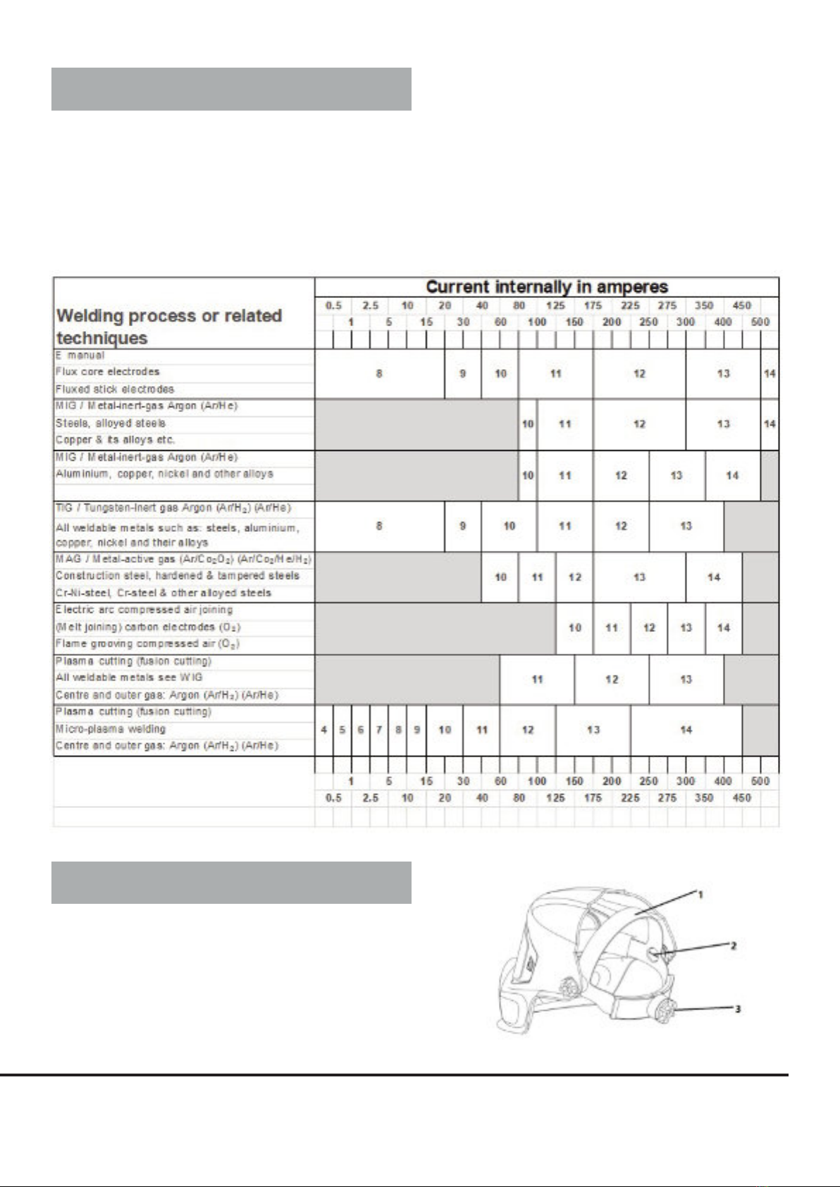
For the recommended lter shades see the chart below.
4. PREOPERATION AND OPERATION
Sparx Single grinding/ welding helmets are fully assembled and
ready to be used after minor adjustments. All welding helmets
are equipped with a comfortable headgear that can be adjusted
in three different ways:
1. Push and move to adjust the “head height”
2. “Rake adjustment” to limit the upper and lower helmet
positioning
3. Push and turn to adjust the “Head Size”
- English -
4 English
Before commencing work please inspect carefully the helmet
and the passive glass for any visible marks, cracks, pitted or
scratched surfaces; damaged surfaces even on protection plates
reduce vision impair protection. If protection plates are scratched,
damaged or built up with spatter please replace.
Welding helmets should not be dropped. Do not place heavy
objects or tools on or inside the helmet as they might damage
the components. If used properly, the welding lter requires no
further maintenance during its lifetime.
5. SERVICE AND MAINTENANCE
Only clean the Sparx Single with mild soap and water. Dry with a
clean cotton cloth.
Please note the use of solvents is strictly prohibited, as they will
damage the mask and lters.
Scratched or damaged visors must always be replaced.
The user must make daily regular checks to ensure that there
is no evident damage. Outer and Inner Visors are consumables
and must be replaced regularly with genuine certied spare parts.
6. REPLACING THE LARGE VISOR
The Large Inner Visor is a protection lens and must be replaced
if broken, damaged or covered with welding spatter to the extent
that vision is impaired.
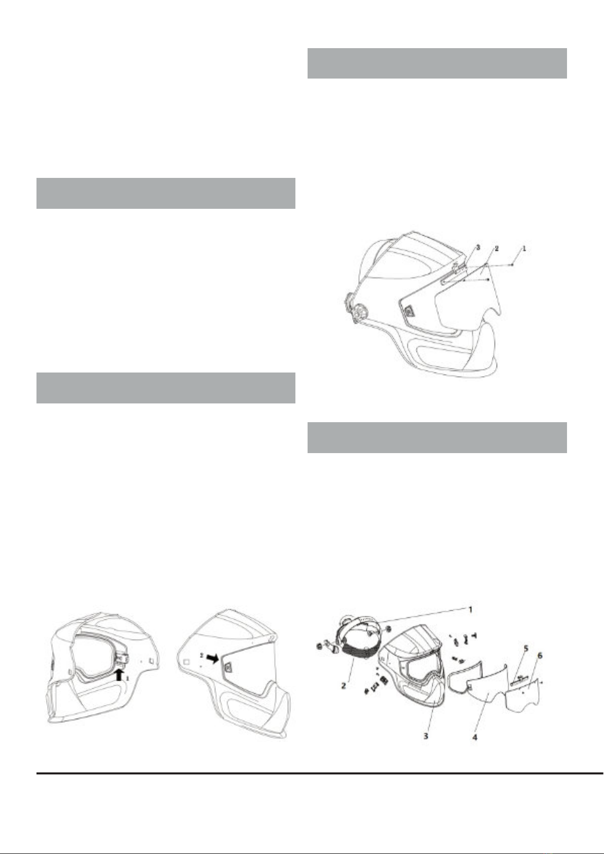
Push the plugs inside the helmet up, see position 1, the Inner
Visor will be released from the helmet; Then pull the Inner Visor
out, see position 2.
Insert the visor, it is necessary to locate the button into the
corresponding hole in the helmet, then push the plugs inside the
helmet down and lock the visor
The user must always make sure the Visor is tted properly and
is locked well and there are no visible gaps.
See the illustrations.
7. REPLACING THE OUTER FLIP VISOR
The Outer ip Visor is a protection lens and must be replaced if
broken, damaged or covered with welding spatter to the extent
that vision is impaired.
The Outer ip Visor is held on a visor holder which is xed on the
shell by two screws. To remove the Visor, loosen the two screws
(No.1), The Visor (No.2) can then be removed.
To replace, change a new visor and t onto the holder (No.3) by
tighten the two screws
8. PART LIST AND ASSEMBLY
ITEM DESCRIPTION PART NO.
1 Headgear of Sparx Single 13.01.041
2 Sweat band of Headgear of Sparx Single 13.01.042
4 Large Inner Visor Sparx Single DIN 1 (clean) 13.02.411
4 Large Inner Visor Sparx Single DIN 2 13.05.005
4 Large Inner Visor Sparx Single DIN 3 13.05.006
4 Large Inner Visor Sparx Single DIN 5 13.05.007
5 Outer visor holder & screws (ip up clip) 13.05.003
6 Outer Flip Visor Sparx Single DIN 5 13.05.008
6 Outer Flip Visor Sparx Single DIN 8 13.05.009
- English -
5English
9. SHADE CALCULATION
Sparx Single have various shade options. To calculate the shade
of Sparx Single, plus the inner visor shade with outer visor shade,
then minus 1(inner visor +outer visor-1).
Examples: Shade 9,
Inner Visor: Shade 2
Outer Visor: Shade 8
Total shade of the helmet :(8+2-1) =9
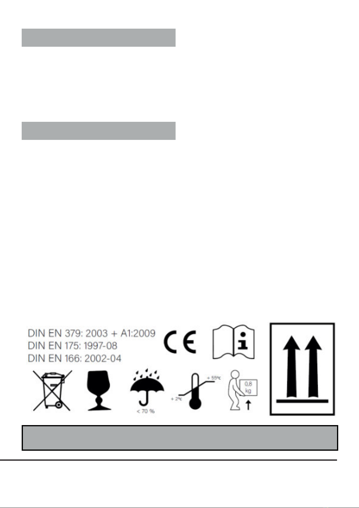
10. HELMET MARKING EXPLANATION
Helmet Marking Explanation:
EN175 B CE - Manufacturer sign
EN175 - Number of Standard
B - Symbol of protection against high speed
particles (120 m/s)
Helmet Visor Marking Explanation:
CSS - Producer
1 - Optical Classication
B - Mechanical strength at 120 m/s
CE - CE conformance mark
ATTENTION if any of these conditions is not kept or
followed, the warranty is automatically invalid.
Other manuals for SPARX SINGLE
1
Table of contents
Other SHINE Motorcycle Accessories manuals


