manuals.online logo
Brands
  1. Home
  2. •
  3. Brands
  4. •
  5. Shire
  6. •
  7. Garden House
  8. •
  9. Shire Elveden User manual

Shire Elveden User manual

1777‐21421‐2rubber
dripbar1600
1143‐4633‐4rubber
dripbar1490
J Shepherd 05/04/2011 A
1. Check all components before
commencing with the construction
of your Elveden
2. Keep all timber dry or your building
will not fit together.
3. We also recommend that you seal
the corner log joints with silicone
sealant (not supplied).
4. We recommend a minimum of two
people required for assembly.
5. Read through all the instructions
before constructing your pine lodge.
6. You will see there is a set of lettered
drawings showing each side of the
building. You will find these letters
printed at one end of each log or in
the slot.
Assembly of Elveden 44mm log ©
Tools required
IMPORTANT!
Wood is a natural product and is therefore
prone to changes in appearance, including
some warping, movement and splitting,
particularly during unusual climatic conditions
(long hot or wet spells of weather). As a natural
occurrence this is not covered by a guarantee.
PLEASE NOTE
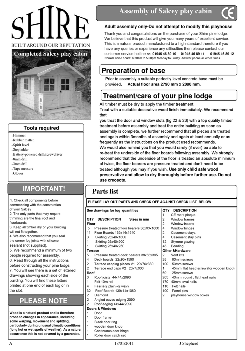
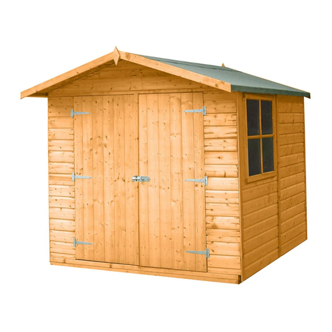
Completed Elveden
IMPORTANT!
The only parts that require cutting are the angled eaves edgings , final roof and floor boards and the skirting.
DO NOT CUT ANYTHING ELSE
●Hammer
●Rubber mallet
●Spirit level
●Stepladder
●Battery-powered drill/screwdriver
●8mm drill
●3mm drill
●Tape measure
●Gloves
●Sharp knife and saw
●string●
Preparation of base
Thank you and congratulations on the purchase of your Shire pine lodge.
We believe that this product will give you many years of excellent service. This is
a natural product manufactured to a high standard therefore if you have any
queries or experience any difficulties then please contact our customer service
hotline on—
01945 46 89 10 01945 46 89 11 01945 46 89 12
Normal office hours: 8.30am to 5.00pm Monday to Friday.
Answer phone all other times.
The base onto which you build your Cabin needs to be flat and level.
We only recommend you use concrete that is a minimum of 10 cm thick
Base size at least 4000mm x 7700mm
Please refer to section B and drawing pages 1& 2 .
Please note that the corner joints protrude over the edge of the base.
Treatment/care of your pine lodge
♦ See drawings for log quantities
♦ See yellow parts list sheet please quote ID number
and your order number in all correspondence
• All timber must be dry to apply the timber treatment.
• Treat with a suitable decorative wood finish immediately. We recommend
that you treat the door and window glazing rebates and beading with a top
quality timber treatment before assembly and treat the entire building as
soon as assembly is complete, we further recommend that all pieces are
treated and again within 3 months of assembly and again at least annually or
as frequently as the instructions on the product used recommends.
• Note the back of the door and window units unscrew so they can be
removed for painting
• We would also remind you that you would rarely (if ever) be able to re-treat
the underside of the floor boards following assembly.
• We strongly recommend that the underside of the floor is treated an
absolute minimum of twice.
• The floor bearers are pressure treated and don’t need to be treated although
you may if you wish. We also recommend that you seal the external corner
joints (fig E2) with silicone sealant (not supplied)
• LUBRICATE LOCK It is extremely important that you lubricate your
lock through the key hole and all moving parts as soon as possible
after assembly and at least at monthly intervals thereafter . Also en-
sure that you regularly operate the lock especially during the winter
or when not in use.
We recommend the wearing of non-slip
protective gloves throughout the
assembly process. We also recommend the wearing of steel capped protective
shoes, protective head gear, safety glasses and full length clothing. If step
ladders are to be used we recommend one person holds the ladder whilst the
other is using them. If necessary a third person should be used. Do not attempt
to erect the building in windy conditions. Follow any safety precautions quoted
by the manufacturer for any equipment you use.
• Every precaution has been taken to ensure that your building has no element
incorrectly placed or possibly hazardous. However prior to use please check
for raised grain or splinters and sand if necessary. Check that all elements
are secure against reasonable force.
IMPORTANT SAFETY INFORMATION
J Shepherd 05/04/2011 B
1. Refer to the two window drawing pages
and to letter codes in contents table above .
The WT (inner) and WD (outer) parts will
be at the top of the window frame.
2. To be sure you can lay all the pieces, in-
cluding inserts together without fixing to
familiarise yourself with the assembly.
3. Make sure the window insert fits inside the
frame with a 5mm gap all around.
4. Lay out the parts WA and WB and WT as
in the inner frame assembly drawing. The
narrowest (25mm) edge to the work bench
and the side the size is the same as the log
thickness as shown in fig A1 . Part WT
must be inside parts WA and part WB
underneath the two WA parts (Fig A1 ) .
5. Pre drill 2 3mm holes at one end of the
WA only and at both ends of the WB parts
(see drawing )and screw together at each
corner,10mm in from the edge (ensuring
each corner is flush) with 2x50mm screw
(fig A1).
7. Measure and mark the centre of the frame
(684mm from the outside fig A2 ) and
position the WM piece (this is two pieces
of wood already fixed side by side), Pre
drill 2 3mm holes in the WB and WT
parts and fix with 2x50mm screws at each
end
Fig A2
8. Layout parts WC ,WD , WE & WJ on top
of the previous assembly as shown in the
outer frame drawing.
Fig A3
9. Mark the first hole position 30mm from the
end of part WC that is adjacent to the WD
part , at the other end central to the WB
part and then the between at approxi-
mately 300mm centres .
10. Note the WC, WD & WE pieces fitted to
the opposite side must be drilled offset to
this side to ensure the screws miss each
other.
11. Place the other WC part underneath and
drill through both pieces with a 3mm drill
(fig A3).
Fig A4
12. Place one of the WC parts on top of the
WA part level with the inside of the frame
and the bottom of the WT part (fig A4).
13. Fix to part WC to WA with 40mm
screws ,spaced as before. (fig A5 & A6)
14. important fix at both ends first ensuring
that they stay flush then the screws in be-
tween again ensuring that parts WA & WC
are flush as you go.
Fig A5
Fig A6
15. Place a WD part on top of a WB part. The
WD part is positioned so there is an
even overhang ( fig A7). Mark out and drill
fix as before. But start at 100mm from the
end of part WD.
Fig A7
16. Drill (not too deep) and screw in each cor-
ner with 40mm screws (fig A8).
Fig A8
17. With a pencil mark the screw centres on the
inside long edge of the frame to help ensure
the hinge screws will miss these screws.
18. Turn frame over and repeat on the other
side fig A9 & A10).
19. Note offset drilled holes from first side to
ensure they miss each other first hole part
WC =30mm part WD =100mm. LEAVE
THE INNER SCREWS LOOSE SO YOU
CAN REMOVE FRAME FROM THE
BUILDING FOR PAINTING.
Fig A9
A Double Window frame
Elveden Assembly –please thoroughly read and familiarise yourself with the instructions and parts prior to assembly
J Shepherd 05/04/2011 C
Fig A10
20. Window insert. Place one hinge on the
inner rebate part of the window; approx.
One hinge width along from the rebate
edge of the longest edge of the insert. The
rounded part of the hinge should sit above
the outer edge of the window. Screw the
inner piece into position ( fig. A11 &A12 )
using the pre drilled holes in the hinge and
3 x 25mm screws. Repeat with the other
hinge. And close the hinges together.
Fig A11– STYLE MAY VARY
Fig A12
21. Place the window into the aperture (fig
A13 ) ensure that part WC is against
the hinges .
22. Secure the window to the frame using 3x
25mm screws per hinge, (fig. A13 ) again
through the predrilled holes in the hinge.
23. Repeat.
Fig A13 example
FigA14
24. Open the window fully in order to fit a
further 2x 25mm screws per hinge
( Fig.A15 ).
Fig A15
25.Fitting the draught excluder. This
must be done before fitting the case-
ment stays.
Fig A16
26. Lay the assembled window unit with
the opening insert downwards onto
your work surface (Fig A16).
27. Position the draught strips so the
rubber is against the opening insert
and fix with 4x25mm oval nails per
strip (Fig A16).
28. Fitting the Casement Stays. There
are two per window. Place the case-
ment stays evenly on the inside of
the window (Fig A17 ) on top of the
draught excluder.
29. Place the 2 pins under each case-
ment stay. Position so that it is not
resting on the window frame and not
so high that the pins are of no use.
Fig A17
30. Fit the Casement Stay (fig A18) on
the window using 2x 25mm screws.
Fig A18
31. Mark where the ‘pins’ will be placed.
Fig A19
32. Secure into position using 4x 25mm
screws - 2 in each pin.
33. Drip bar. Turn the window unit over
so the opening insert is uppermost .
Fig A20
34. Position the drip bar he drip bar by
measuring 45mm down from the top
of the WD part above the hinges
and fix the drip bar with 3x25mm
screws. Repeat with the other win-
dow unit
35. Put the completed units to one side
until required .
36. Note do not glaze until all parts have
been treated and the units fitted in the
building
1. Refer to letter codes in the contents
table and also use the doors as a
gauge to ensure correct assembly
(assembly similar to but not the same
as the windows). SEE LARGE DRAW-
INGS. Do not tighten the inside of
the frames so you can remove for
treatment .
2. Lay out the parts DA and DB as in fig
B1. The 25mm edge to the work sur-
face
B Door Frame-Double door only
J Shepherd 05/04/2011 D
Fig B1
3. Parts DB must be inside parts DA
Fig B2
4. Drill both ends of the DA and screw
together at each corner, 10mm in from
the edge (ensuring each corner is
flush) with 2x50mm screws (fig B2).
Fig B3
5. Layout parts DC, DD & DE as in fig
B3 .
6. Mark the first hole position 30mm from
each end of part DC and then the rest
at approximately 200mm centres.
7. Note the DC, DD & DE pieces fitted to
the opposite side must be drilled
offset to this side to ensure the screws
miss each other.
Fig B4
8. Place the other DC part underneath
and drill through both pieces with a
3mm drill (fig B4)
Fig B5
9. Place one of the DC parts on top of the
DA parts level with the inside of the
frame (fig B5)
.
Fig B6
10. Fix to part DC to DA with 40mm screws
(fig B6 &B7) important fix at both ends
first ensuring that they stay flush then
the screws in between again ensuring
that parts DA & DC are flush as you go.
Fig B7
11. Place a DD part on top of a DB part.
the DD part is positioned so there is an
even overhang (figB7). Mark out and
drill fix as steps 8 to 10. But start at
100mm from the end of part DD.
Fig B8
12. Drill (not too deep) and screw in each
corner with 40mm screws (fig B9).
Fig B9
13. With a pencil mark the screw centres
on the inside long edge of the frame to
help ensure the door hinge screws will
miss these screws.
14. Turn frame over and repeat steps 5 to
13 on the other side
15. Note offset drilled holes from first
side to ensure they miss each other
first hole part DC=40mm part DD
=110mm
1. Lay doors on the floor, as you would
view them from the inside of the build-
ing. Make sure the door with the lock is
situated on the left when viewed from
the bottom.
2. Lay the outer frame in position (fig C2).
3. The hinges are fitted on the longest
outside edge of the doors.
4. Make a visual judgement to the gap top
and bottom of the doors then transfer
the screw centre marks (step B 13) to
the doors. This is to ensure the hinge
screws miss the frame screws.
5. Lift off the outer frame making note of
which way around you have put it.
12. Place the hinges as shown in fig 36
Screw the inner piece of the hinge to
the door with 2 x 25mm screws.
Fig C1
7. Close the hinges and lay the frame
assembly over the doors (fig C2).
DA DA
DB
DB
DC DC
DD
DE
C Fit Doors
J Shepherd 05/04/2011 E
Fig C2
8. Make a visual judgement to set an
even gap top/bottom of the doors and
secure each hinge with 1x25mm
screws (fig C3). Ensure the hinges
are tight against the face of the
doorframe.
Fig C3
9. Stand the assembly up. Note two
people needed for this step. Open the
doors and secure hinges with
remaining 4x25mm screws per hinge.
10. Lay the assembly down again with the
doors facing down and fix the draught
excluder as with the windows using
9x35mm oval nails for either side and
9x35mm oval nails each top and bot-
tom. Take note of where you are going
to put the door bolts ( step 12).
11. Drip bar .Turn the unit over and
measure down 45mm and position and
fix with 6x25mm screws as previously
done with the window unit.
Fig C4
12. Fit two bolts on the door without the
lock (fig C4). The top bolt should be
positioned just below the draught ex-
cluder. Fix with 4 screws supplied.
13. Extend the bolt to meet the frame with
the cranked part as far from the edge
as you can and mark then drill a 10mm
hole (into , not through the frame) to
take the bolt.
14. Align the catch plate and fix with 4
screws supplied
15. Put the door assembly to one side until
required.
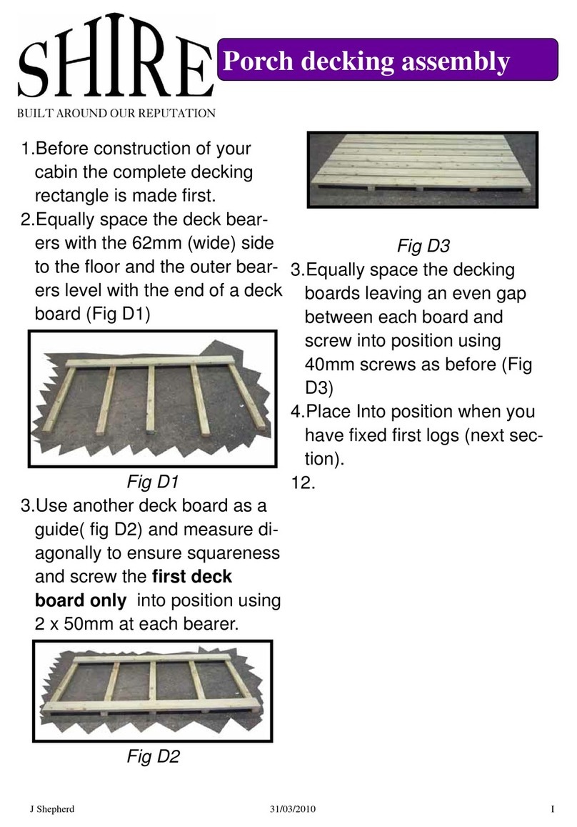
1. Before construction of your cabin the
complete decking rectangle is made
first.
2. Equally space the deck bearers with
the 62mm (wide) side to the floor and
the outer bearers level with the end of a
deck board (Fig D1)
Fig D1
3. Use another deck board as a guide( fig
D2) and measure diagonally to ensure
squareness and screw the first deck
board only into position using 2 x
50mm at each bearer.
Fig D2
Fig D3
3. Equally space the decking boards leav-
ing an even gap between each board
and screw into position using 40mm
screws as before (Fig D3)
4. Approximately place Into position at the
centre front of the base (final position
determined with bearers and logs from
next section.
See drawing pages 1&2
1. Following the instructions below
and with the help of the drawing
pages assemble your building up to
and including the gables
Fig E1
2. Take the half height log (A1) that sit on
the bearers & that you see the bearer
ends . Mark the floor bearer centres,
but not the outer bearers, from one
end (fig E1 drawing pages )
Fig E2
3. Place the ’A1, E1 ,K1 & L1’ logs
against each other and transfer all the
lines across (fig E1 ).
4. The outer bearers and door panel wall
bearers are 3 bearers nailed together
at approx. 300mm centres with 70mm
nails at a slight angle (fig E2 & E6 ).
5. The bearers stand with the narrowest
edge to the floor (fig E3 ) and their
ends flush with the A1 logs face
Fig E3
6. Assemble the first row of logs on top of
the bearers by placing the half height
logs (A) in position and then the first of
the logs from each wall (B) that run
parallel to the bearers on top of them.
7. The logs are assembled with the
tongues upwards
8. Position the outer bearers so the outer
log sits 5mm in from the outer face (fig
E4) of the side and flush with the front
logs.
D Decking
E Floor Bearers & First Logs
J Shepherd 05/04/2011 F
Fig E4
At the centre marks ( fig E5 (previous
steps ) drill through for fixing to the
bearers .
Fig E5
Important
10. Measure corner to corner, as building
must be square
Fig E6
11. Also measure length at the centre of
the building from wall to wall (A1 toA1)
to ensure correct length before fixing to
joists with 1x 80mm screw (fig E5 & E6)
at each bearer and place the deck in
position.
12. This is the bottom of all four walls now
ready to be built upon.
See drawing pages
1. Using parts list for each wall layout
correct quantity (fig F1) of each com-
ponent for relevant wall (i.e. front, back)
in suitable position for ease of assem-
bly.
Fig F1 example
2. The walls can now be assembled as
per drawing pages above. Start build-
ing walls by placing all the logs from
front and back and then from side and
side
3. The logs are assembled with the
tongues upwards
4. Each log needs to be tapped home to
log below using timber block supplied
and a rubber mallet (fig F2).
Fig F2
UNDER NO CIRCUMSTANCES MUST
THE DOOR OR WINDOW FRAMES BE
NAILED TO THE LOGS .The logs must be
fee to move within the frame lots to allow for
expansion and contraction. AS SOON AS
YOU FIT DOOR UNIT FIT HANDLES
AND UNLOCK DOOR
1. Door unit must be placed into position
after the first two layers of full logs have
been assembled
2. Slide unit into aperture from above (Fig
G1 & G2) ensuring unit is completely
down and in position.
Fig G1 EXAMPLE
Fig G2
3. Window units are fitted as above (fig
G3) when you have built up to the cor-
rect height
Fig G3 example
4. Note Door and window units do not
require fixing to the logs
5. Once the door and window units are in
place continue assembling the walls as
before but slide the logs into the door
or window frame (fig G4) from above
then tap them down.
Fig G4
6. Continue building until you get to the
height were the gable starts.
See drawing pages 3 & 5 THERE MAY
BE LESS SLOTS FOR THE JOISTS
TOWARDS THE FRONT OF THE
BUILDING . STUDY THEM CAREFULLY
1. Assemble the gables with the walls .
2. Lay the largest gable on the floor
and place the others on top in line to
help ensure you fit them on the
building the correct way around.
3. Once gables are in place knock down
all the walls again as in fig C2 to en-
sure all the walls are fully home
4. Fix the gable with1x80mm screw at
each end (fig E1 and as shown on the
drawing pages (Some screws may go
into roof joists)
F Walls
G Inserting windows and doors
H Gables
J Shepherd 05/04/2011 G
Fig H1
1. Fit roof joists into slots provided in the
gable sections (fig I1 I2). NOTE there
are five types of bearer , SEE LOG
SHEET FOR DRAWINGS
SEE LARGE FIG I2 DRAWING AT
END OF INSTRUCTION PACK

Fig I1
2. Fit the 5 RB1 bearers in the large room
first starting at the back working
forward, and then the RB3 bearers
across the porch.
3. Next slot the 7 RB4 bearers in the small
room. All these bearers will either sit
above or all sit below the RB1 bearers
in the double slots. ENSURE THEY
ARE PARALLEL TO THE WALLS.
4. Next slot the RB5 bearer into position
at the top centre so it buts up to the end
of the RB1 bearer . Ensure it is level
with the RB4 bearer it is next to and
screw together with 70mm screws at
600mm centres.
Fig I2
5. Repeat with the RB2 Bearer at the
other end.
6. Measure the distance between each
roof joist and the roof joists and walls to
ensure all components are fully home
before continuing.
1. There are eaves edging strips for the
building (2 places) (These may need
cutting to fit ).
2. Position the eaves edging strips ( fig J1
& J2) level at both ends with the gable
angle (front and back walls) and screw
to the wall with 50mm screws at ap-
proximately 400 centres.
Fig J1
Fig J2
3. The first roof board is now ready to be
positioned (fig G3).Bevel edge down-
wards.
4. NOTE only the final boards need
trimming. Fit the boards with the cham-
fer downwards
Fig J3
5. Start at the front, place the board level
with the end of the roof bearers and
central over the middle bearer to pro-
duce an even overhang (fig J3).
6. Fix each board into place at the roof
bearers and angled eaves edgings us-
ing two 40mm ROUND HEAD nails at
each bearer & eaves edging
Fig J4
7. The final roof board will need to be cut.
Place it in position and measure the
distance between the end of the roof
bearers and the edge of the board. This
will tell you how much you need to cut
off (fig J4).
8. Next fit the roof edgings to the outer
edges of the roof boards with 50 mm
screws at approximately 300mm cen-
tres (Fig. J5).
1. Packs of shaped tiles and strips rec-
tangular tiles for the eaves and ridge
have been supplied. (SEE CON-
TENTS )
2. Use tiles randomly from the packs of
tiles supplied to even out the colour
match.
3. remove all dust and sharp edges
from the roof boards.
Read the entire section before starting.
Fig H1
5. Measure the length of the roof (fig H1)
and mark the centre of the roof and
repeat the other side .
Fig H2
6. Lay out the row of ridge strips and
shaped tiles and adjust the position of
the tiles to get the least waste possible
and if you can the piece that you trim
off can be used at the other end.
7. Place the first ridge strip so it is central
to the mark (or your adjusted position )
and over hanging the roof edging by
10mm.
8. Measure the distance the tile is up the
roof and mark it at either end of the
roof. Tack the string at the marks at
either end to use as a guide to keep the
tiles level. (use this method to keep all
your tiles square.
9. remove the backing film and fit the row
I Roof joists
J Roof boards & edgings
K-1 Tile roof option (see K2 for felt)
J Shepherd 05/04/2011 H
of eaves tiles. Nail the centre of each
individual tile 1 cm down from the edge
with one felt nail. (fig H2) and 2 nails at
the bottom where they will be covered
by the next tile layer.
Fig H3
10. The installation of roofing shingles is
usually started from the middle of the
slope, so that the tabs of the shingles
cover the end joints and perforations of
the eaves shingles.
11. The lower edge of the first row of shin-
gles is aligned with the bottom edge of
the eaves shingles, so that the line
of the eave appears clean and straight
when seen at an upward angle from the
ground. The roofing shingles are fixed
with roofing nails (4 pieces / shingle) as
shown in the figures above, some 30
mm above the bottom of each notch
along their centre lines
12. .The shingles will bond to one another,
but they are nailed to the roof.
Fig H4
14. Use a sharp knife to trim the tiles level
with the end of the roof. You should be
able to use the waste piece on the
other end of the roof.
Fig H5
15. On the ridge, the topmost shingles are
cut along the ridge line (not folded over
the ridge!)(fig H5).
16. By folding and tearing an eaves shingle
as shown above (fig H5 ) you will have
three ridge capping shingles.
17. On a pitched roof, installation is started
from either end so that the adhesive
edge of the first ridge capping shingle is
aligned along the verge, on top of the
roofing shingles. The ridge capping
shingle is nailed to the decking from the
non-adhesive edge with four nails (two
either side of the ridge ).
18. Ridge capping shingles are laid cen-
trally on the ridge in such a way that the
adhesive strip on the underside over-
laps the previous sheet by some 50
mm covering the nail heads. The pro-
cedure is repeated along the length of
the ridge. Fig J5
1. 2x10m and 1x6m rolls of felt have been supplied.
2. layout a 10m roll and cut into 410cm lengths (Fig
K1).You can use a board as a straight edge.
3. Repeat with all the felt.
Fig k1
4. Starting at the lower edge (eaves) place 1 piece
from front to back of the building.
5. An overhang of approximately 50mm should be
allowed at the front and the back (all felt strips) and
the length of the eaves edgings at the side (Fig K2
& K3).
Fig K2
6. Secure with felt nails at approximately 100mm
spacing. But only a couple along the high edge at
this time (nailed with overlap).
Fig K3
7. Repeat on the other side.
8. Place the next piece of felt over the high point of
the roof (ridge) overlapping the lower pieces either
side then nail as before.
9. Nail with felt nails at each roof bearer leaving
space for fixing the Fascia's.
10.
1. Fascia boards can now be drilled and
screwed ( fig L1 ) with 1x 50mm screw
at each roof bearer and the roof edg-
ings.
Fig L1
2. Drill diamond and screw with 2x50mm
screws . (fig L2)
Fig L2
1. The floor is fitted working from front to
back with 40mm nails Bevel edge
downwards.
2. Position the first floorboard under the
doorframe (Fig M1), with the groove
against the wall.
Fig M1
3. Fix into position with two nails at each
floor bearer (Fig M2& M3).
Fig J2
K 2 Felt Roof
L Fascia
M Floor
J Shepherd 05/04/2011 I
Fig M3
4. Continue with remaining floorboards
until you have three remaining.
5. Place these in position without nailing
them down, as the last floorboard will
require trimming.
6. Measure the distance between the last
full board and the wall (Fig M4). This
measurement is then marked on the
final board and then cut to Fit , leaving
the groove on the board .
Fig M4
7. Curl the boards up ( fig J5 ) to put it
into position and nail the remaining
boards before
Fig M5
8. Cut the skirting boards to suit and fix
with 40mm oval nails at approx.
400mm centres (fig M6)
Fig M6
After painting
1. NOTE ensure that you have treated
the beading and the rebate where the
glass fits before fixing the glazing.
2. Place glazing material into the aperture
of each window.
3. Hold into position with four pieces of
beading . The beading may need to be
swapped around to get the best fit.
When satisfied secure into position
using 2x15mm panel pins per piece of
beading. ( fig N1 )Repeat for all window
and door apertures.
Fig N1
N Glazing

Other Shire Garden House manuals

Shire Rose Arbour User manual

Shire

Shire Rose Arbour User manual

Shire Larkspur User manual

Shire

Shire Larkspur User manual

Shire Den User manual

Shire

Shire Den User manual

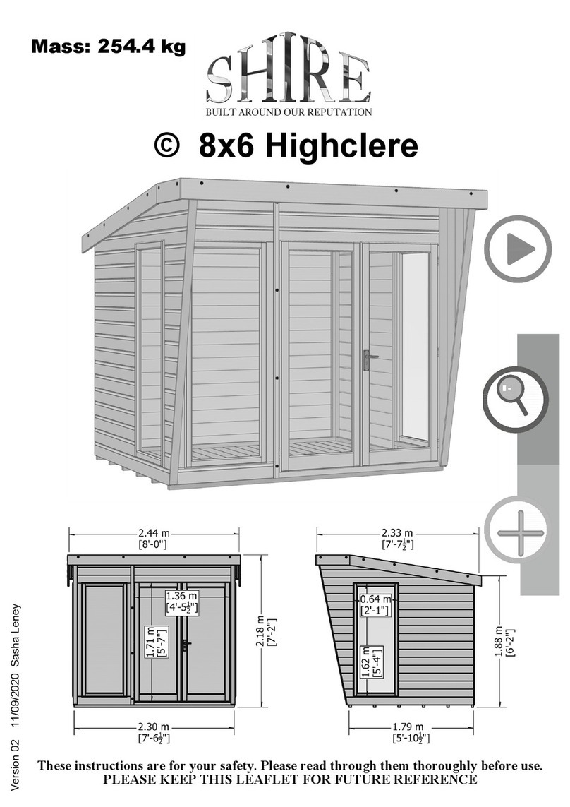
Shire Highclere User manual

Shire

Shire Highclere User manual

Shire Lodge Playhouse User manual

Shire

Shire Lodge Playhouse User manual

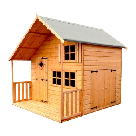
Shire Crib Playhouse User manual

Shire

Shire Crib Playhouse User manual

Shire GSHE0706DSL-1AA User manual

Shire

Shire GSHE0706DSL-1AA User manual

Shire 46034 User manual

Shire

Shire 46034 User manual

Shire 7x5 Haddon 2022 User manual

Shire

Shire 7x5 Haddon 2022 User manual

Shire Arbour Foxglove User manual

Shire

Shire Arbour Foxglove User manual

Shire Abri Apex User manual

Shire

Shire Abri Apex User manual

Shire Alderney Apex User manual

Shire

Shire Alderney Apex User manual

Shire 6x4 Bar User manual

Shire

Shire 6x4 Bar User manual

Shire 8x8 Sun Pent Manual

Shire

Shire 8x8 Sun Pent Manual

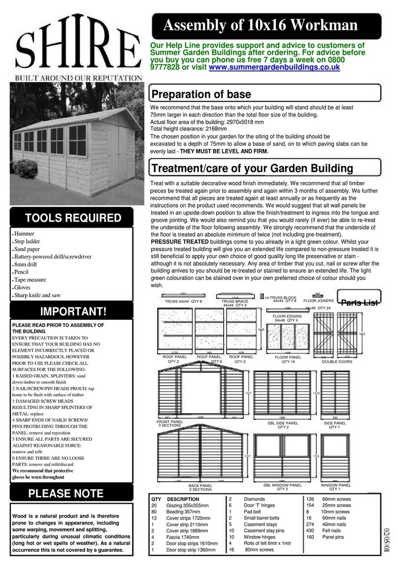
Shire Workman 10x16 User manual

Shire

Shire Workman 10x16 User manual

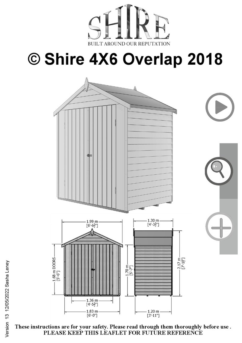
Shire 4X6 Overlap 2018 User manual

Shire

Shire 4X6 Overlap 2018 User manual

Shire Casita 2016 User manual

Shire

Shire Casita 2016 User manual

Shire Aster 2020 User manual

Shire

Shire Aster 2020 User manual

Shire 10x6 Sun Pent Manual

Shire

Shire 10x6 Sun Pent Manual

Shire Salcey User manual

Shire

Shire Salcey User manual

Shire Flat Pack Loft User manual

Shire

Shire Flat Pack Loft User manual

Shire Jailhouse User manual

Shire

Shire Jailhouse User manual

Shire Paradise Bar User manual

Shire

Shire Paradise Bar User manual

Shire Garden Store User manual

Shire

Shire Garden Store User manual

Popular Garden House manuals by other brands

Lemeks Palmako PA28-5830-1 Assembly, installation and maintenance manual

Lemeks

Lemeks Palmako PA28-5830-1 Assembly, installation and maintenance manual

Palmako FR28-5030-1 Assembly, installation and maintenance manual

Palmako

Palmako FR28-5030-1 Assembly, installation and maintenance manual

Dunster House DUTCH BARN I installation manual

Dunster House

Dunster House DUTCH BARN I installation manual

Palmako Roger FR70-5656-1 installation manual

Palmako

Palmako Roger FR70-5656-1 installation manual

Yardistry YM12842 Installation and operating instructions

Yardistry

Yardistry YM12842 Installation and operating instructions

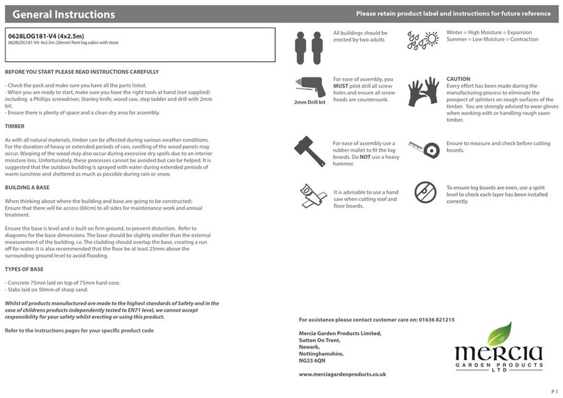
Mercia Garden Products 01OVLPA0406DDNW-V General instructions

Mercia Garden Products

Mercia Garden Products 01OVLPA0406DDNW-V General instructions

OLT STU128-Metal Assembly manual

OLT

OLT STU128-Metal Assembly manual

Palmako FR28-3131 manual

Palmako

Palmako FR28-3131 manual

Palmako FRA28-2121 installation manual

Palmako

Palmako FRA28-2121 installation manual

Décor et Jardin Spirit 62222S900 Assembly Notice

Décor et Jardin

Décor et Jardin Spirit 62222S900 Assembly Notice

Lemeks Palmako EL18-4533 Assembly, installation and maintenance manual

Lemeks

Lemeks Palmako EL18-4533 Assembly, installation and maintenance manual

Palmako FR44-4040-1 Assembly, installation and maintenance manual

Palmako

Palmako FR44-4040-1 Assembly, installation and maintenance manual

Palmako Aubagne 15 Assembly, installation and maintenance manual

Palmako

Palmako Aubagne 15 Assembly, installation and maintenance manual

Mercia Garden Products 03DTSHPN0409SHPB-V1 General instructions

Mercia Garden Products

Mercia Garden Products 03DTSHPN0409SHPB-V1 General instructions

Mercia Garden Products 0634RANE0504FGDD2TW1SW-V1 General instructions

Mercia Garden Products

Mercia Garden Products 0634RANE0504FGDD2TW1SW-V1 General instructions

Universo Consumer Products CK3421 Assembly instructions

Universo Consumer Products

Universo Consumer Products CK3421 Assembly instructions

Mercia Garden Products 01DTOVRA0604SDFW-V1 manual

Mercia Garden Products

Mercia Garden Products 01DTOVRA0604SDFW-V1 manual

Karibu TALKAU 6 manual

Karibu

Karibu TALKAU 6 manual

manuals.online logo
manuals.online logoBrands
  • About & Mission
  • Contact us
  • Privacy Policy
  • Terms and Conditions

Copyright 2025 Manuals.Online. All Rights Reserved.