manuals.online logo
Brands
  1. Home
  2. •
  3. Brands
  4. •
  5. Shire
  6. •
  7. Garden House
  8. •
  9. Shire Garden Store User manual

Shire Garden Store User manual

Garden Store 4 x 2 Instructions
Thank you and congratulations on the purchase of your Shire Garden Building. We
believe that this product will give you many years of excellent service. This is a natural
product manufactured to a high standard therefore if you have any queries or experience
any difficulties then please contact our customer service hotline 01945 46 89 10 or
01945 46 89 11 or 01945 46 89 12.
Preparation of Base
We recommend that the base onto which your building will stand should be at least 75mm
larger in each direction than the total floor size of the building.
Actual floor area of the building: 1190 x 590mm
Total height clearance: 1520mm
The chosen position in your garden for the siting of the building should be excavated to
a depth of 75mm to allow a base of sand, on to which paving slabs can be evenly laid - THEY
MUST BE LEVEL AND FIRM.
Treatment/Care of your Garden Building
Treat with a suitable decorative wood finish immediately. We recommend that all timber
pieces be treated again prior to assembly and again within 3 months of assembly. We
further recommend that all pieces are treated again at least annually or as frequently as
the instructions on the product used recommends.
We would suggest that all wall panels be treated in an upside-down position to allow the
finish/treatment to ingress into the tongue and groove jointing.
We would also remind you that you would rarely (if ever) be able to re-treat the
underside of the floor following assembly. We strongly recommend that the underside
of the floor is treated an absolute minimum of twice (not including pre-treatment).
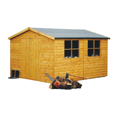
Completed Garden Store
Tools Required
Posidrive screwdriver (electric is best)
Drill, 6mm drill bit and 8mm drill bit
Hammer
Sandpaper (to smooth any rough edges)
Cutting knife
Tape measure
Step ladder
Ruler
Pencil
Saw
IMPORTANT!
PLEASE READ PRIOR TO ASSEMBLY OF
THE BUILDING
EVERY PRECAUTION IS TAKEN TO
ENSURE THAT YOUR BUILDING HAS NO
ELEMENT INCORRECTLY PLACED OR
POSSIBLY HAZARDOUS, HOWEVER
PRIOR TO USE PLEASE CHECK ALL
SURFACES FOR THE FOLLOWING:
1 RAISED GRAIN, SPLINTERS: sand
down timber to smooth finish
2 NAIL/SCREW/PIN HEADS PROUD: tap
home to be flush with surface of timber
3 DAMAGED SCREW HEADS
RESULTING IN SHARP SPLINTERS OF
METAL: replace
4 SHARP ENDS OF NAILS/ SCREWS/
PINS PROTRUDING THROUGH THE
PANEL: remove and reposition.
5 ENSURE ALL PARTS ARE SECURED
AGAINST REASONABLE FORCE:
remove and refit
6 ENSURE THERE ARE NO LOOSE
PARTS: remove and refit/discard
WE RECOMMEND THAT PROTECTIVE
GLOVES BE WORN THROUGHOUT
QTY DESCRIPTION
Building
1 Floor A
2 Back Panels B
2 Side Panels C
2 Framework 34x34x1120mm D
2 Doors D1
1 Door Coverstrip 46x12 D2
1 OSB Roof (1220mm x 640mm) E
1 Piece Felt F
6 Roof fixing blocks G
5 Cover strips 46x12 H
2 Door (weather) strips 28x12 I
PLEASE LAY OUT PARTS AND CHECK OFF AGAINST CHECK LIST BELOW:
Wood is a natural product and is therefore
prone to changes in appearance, including
some warping, movement and splitting,
particularly during unusual climatic conditions
(long hot or wet spells of weather). As a natural
occurrence this is not covered by a guarantee.
PLEASE NOTE
BUI T AROUND OUR REPUTATION
F
E
G
G
C
H
I
I
A
B
B
D
D2
D
D1
C
QTY DESCRIPTION
Accessories
6 Door Hinges
1 Pad-Bolt & Housing
2 Bolts
4 L-Shaped Brackets
16 60mm Screws
28 40mm Nails
70 25mm Screws
50 13mm Felt Nails
8 10mm Screws
6 40mm Screws
Parts List
01/08
1Check and ensure that no raised grain or
splinters are evident on timber components.
Sand down any raised grain or splinters
using fine grade sandpaper.
2Check that all screw, nail and pin heads are
properly tapped home and are not proud of
the timber surface.
3Check and ensure that no screws, nails or
pins protrude through any panel.
4Check and ensure that all parts are properly
secured against reasonable force.
5Do not apply decorative wood
finish/treatments to wet or damp timber.
Please observe the instructions of the wood
finish/treatment manufacturer.
Assembly Completion Checklist
Assembly of Building -
PLEASE READ INSTRUCTIONS PRIOR TO ASSEMBLY
F
-
Finishing Touches
E
-
Hang Doors
D
-
Coverstrips
A
-
Floor & Walls
1 Place down floor ‘A’ on a flat level
surface.
2 Place one back panel ‘B’ with a side
panel ‘C’. Note: the back panels and
the front assembly are to go inside
the side panels and that the
overhang on the panels sit over the
edge of the floor. Drill then screw
together using 2 x 60mm screws.
Do not fix to the floor until all the
walls are in position.
3 Fix the other back Bto the first
back again using 2 x 60mm screws.
4 Fix the other side panel C to the
other end again using 2 x 60mm
screws.
5 Position one of the part D
framework between the the side
panels at the top ensuring they
are level and and flush with the
framework and fix with an angle
bracket and 2 x 25mm screws at
each end.
6 Repeat step 5 with the other D
framework but at the bottom
making sure it is flush with the front
of the floor.
B
-
Door Assembly
1 Lay down door
panel ‘D’ onto
the floor, shiplap
facing up. The
top of the panel
is the one
without the
overhanging
shiplap.
2 The diagonal
door bracing on
the inside points
towards the
door opening.
The hinges are
to be placed on
the boarding,
which covers
each horizontal
door backing.
1 Space the doors from the top of the
door panel framework approx. 8mm.
2 Fix the moveable part of each hinge
to the cover strips of the side panels
‘C’ using 3 x 25mm screws per
hinge.
3 Place the
pointed part
of the hinges
onto the
doors with the
round
moveable part
overhanging
the edge. Fix
the pointed part in place using
4x 25mm screws per hinge.
Inside of door - for
positions in relation
to bearers.
DO NOT
FIT HINGES &
LOCKS ON INSIDE
C
-
Fit Roof & Felt
1 Place OSB Roof panel ‘E’ onto the
building. It should sit flush at the
back and sides but overhang a
little at the front. Draw a line all
around the inside of the roof.
2 Remove the roof and place on a flat
surface. Take one of the roof fixing
blocks and place it centrally inside
the line for the side panel. Draw a
line the other side and at each end.
3 Drill through the roof panel centrally
between the lines at both ends. Fix
the block with 2 x 25mm screws
from the other side. Repeat at the
other end and in two places along
the back and then the front.
4 FELTING –
place the
piece of felt
on a smooth
surface so
not to
damage it,
place the roof panel on the top so
the blocks are facing upwards. Fold
the felt over the roof panel (trim if
necessary) and fix at approximately
100 mm spacing with felt nails.
5 Place the roof into position and drill
then fix through the blocks with one
60mm screw per block.
1 Fit two bolts to
the inside, inner
edge of the left
door 'E'. The
top bolt should
be positioned
so that the solid
part of the bolt
finishes flush
with the top of
the door. Fit
using 4x 10 mm
screws. Hold
the door tightly
closed. Move
the moveable
part of the bolt
and mark where
this meets the door frame. Drill
a small hole using an
8 mm drill bit.
3 Place the
padbolt in
position on the
outside of the
right hand door
'D' directly over
the central
horizontal brace. Ensure the
edge is flush with the upright
edge. Secure using 4x 25 mm
screws using the round holes only.
2 The bottom
bolt should fit
flush with the
bottom edge of
the door. Fit
as for top bolt.
4 Place padbolt
housing in
position to
accommodate
the padbolt.
Secure using
2x 25 mm screws using the round
holes only.
5 Place outside door cover strip 'D2'
flush with the top and bottom of
the door and mark top and bottom
of padbolt position.
6 Attach the door stop strips above
and below the padbolt. Half of each
strip should overhang the edge of
door 'D' and when closed also
overhang the left hand door 'E'.
Secure using 6x 25 mm screws.
1 Screw all side panels to the floor on
the inside of the building using 1 x
60mm screw per separate panel.
7 Fix weather
strips ‘I’ flush to
the inside edge
of the sides of
the door
aperture. Fix
using 4 x 40mm
nails per strip.
1 Fix the cover strips
in position where
the panels meet.
There will be three
slightly longer cover
strips, these are for
the back. Secure
strips using 4x
40mm nails each.
Cut out
section as
marked
G
-
Secure Walls to Floor
Other Shire Garden House manuals

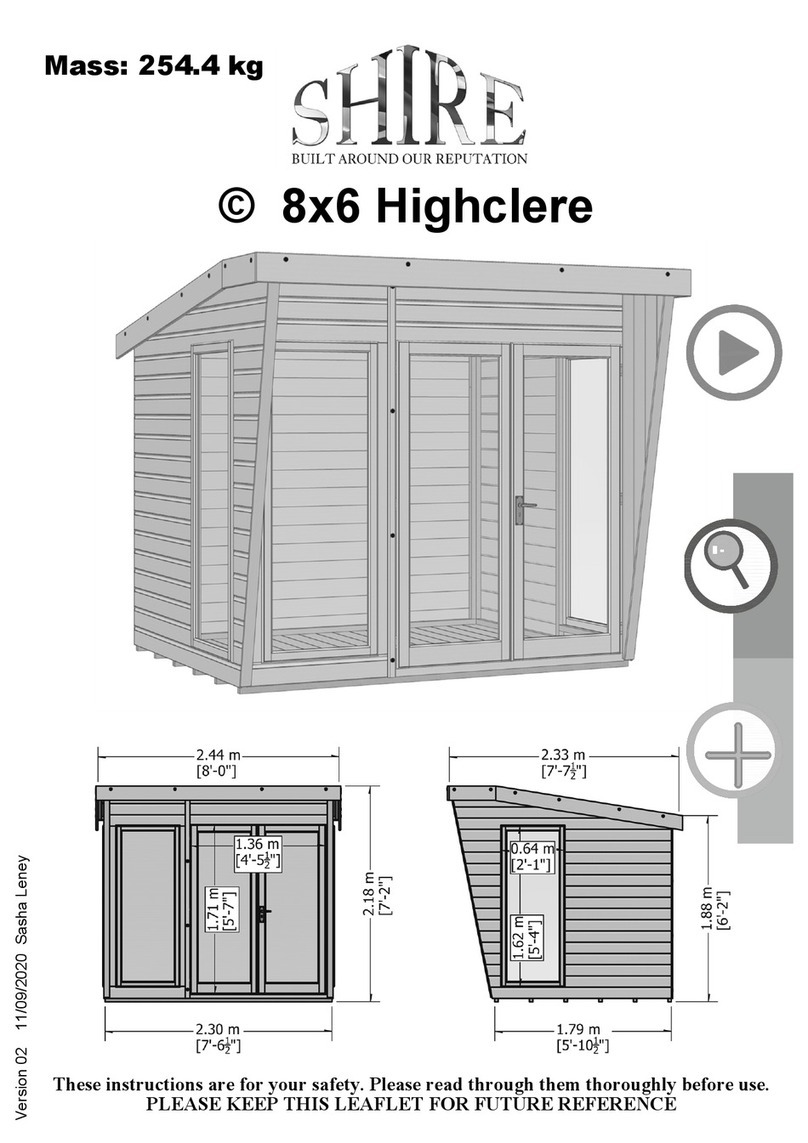
Shire Highclere User manual

Shire

Shire Highclere User manual

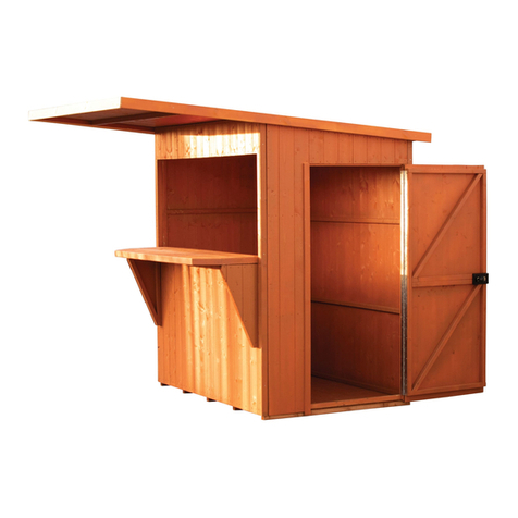
Shire Paradise Bar User manual

Shire

Shire Paradise Bar User manual

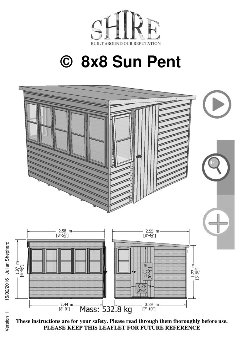
Shire 10x10 Sun Pent Manual

Shire

Shire 10x10 Sun Pent Manual

Shire Arbour Foxglove User manual

Shire

Shire Arbour Foxglove User manual

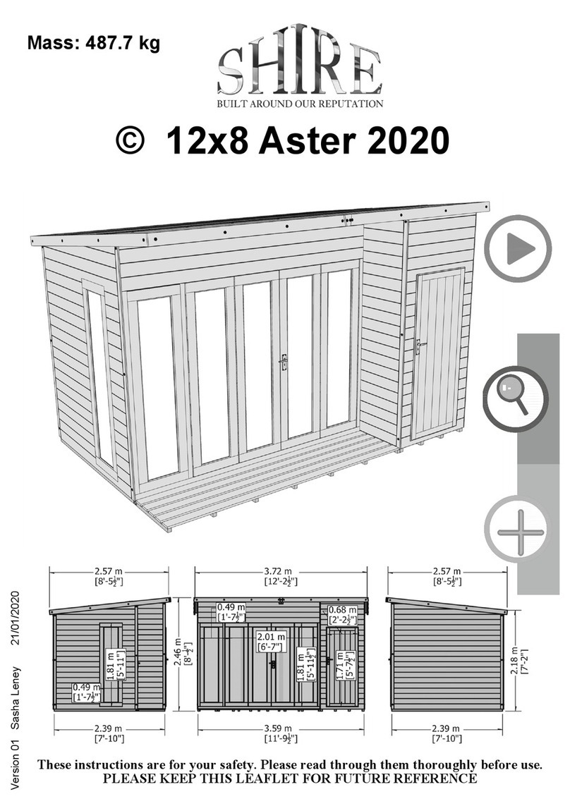
Shire Aster 2020 User manual

Shire

Shire Aster 2020 User manual

Shire Casita 2016 User manual

Shire

Shire Casita 2016 User manual

Shire Bison Workshop User manual

Shire

Shire Bison Workshop User manual

Shire 4X6 Overlap 2018 User manual

Shire

Shire 4X6 Overlap 2018 User manual

Shire Larkspur User manual

Shire

Shire Larkspur User manual

Shire Rose Arbour User manual

Shire

Shire Rose Arbour User manual

Shire Abri Apex User manual

Shire

Shire Abri Apex User manual

Shire 46034 User manual

Shire

Shire 46034 User manual

Shire 10x6 Sun Pent Manual

Shire

Shire 10x6 Sun Pent Manual

Shire 6x4 Bar User manual

Shire

Shire 6x4 Bar User manual

Shire Lodge Playhouse User manual

Shire

Shire Lodge Playhouse User manual

Shire Jailhouse User manual

Shire

Shire Jailhouse User manual

Shire Elveden User manual

Shire

Shire Elveden User manual

Shire Guernsey 7x10 User manual

Shire

Shire Guernsey 7x10 User manual

Shire Den User manual

Shire

Shire Den User manual

Shire GSHE0706DSL-1AA User manual

Shire

Shire GSHE0706DSL-1AA User manual

Shire Crib Playhouse User manual

Shire

Shire Crib Playhouse User manual

Shire 7x5 Haddon 2022 User manual

Shire

Shire 7x5 Haddon 2022 User manual

Shire Alderney Apex User manual

Shire

Shire Alderney Apex User manual

Shire Flat Pack Loft User manual

Shire

Shire Flat Pack Loft User manual

Popular Garden House manuals by other brands

Mercia Garden Products 0628RANE0403HGDD2SW-V1 General instructions

Mercia Garden Products

Mercia Garden Products 0628RANE0403HGDD2SW-V1 General instructions

Lemeks Palmako FR28-3834-1 Assembly, installation and maintenance manual

Lemeks

Lemeks Palmako FR28-3834-1 Assembly, installation and maintenance manual

Interline Rauma 3 Building instructions

Interline

Interline Rauma 3 Building instructions

Palmako Sandy 3.0 installation manual

Palmako

Palmako Sandy 3.0 installation manual

Luoman Lillevilla Kukkia Assembly and Maintenance

Luoman

Luoman Lillevilla Kukkia Assembly and Maintenance

Billyoh INS-0042 Building instructions

Billyoh

Billyoh INS-0042 Building instructions

ARREDO 87778S000 Assembly Notice

ARREDO

ARREDO 87778S000 Assembly Notice

Palmako ELT18-3422-1 installation manual

Palmako

Palmako ELT18-3422-1 installation manual

Keter MANOR 6x5DD Assembly instructions

Keter

Keter MANOR 6x5DD Assembly instructions

Rowlinson Arley Summerhouse Assembly instructions

Rowlinson

Rowlinson Arley Summerhouse Assembly instructions

for Living Essex Grill Gazebo L-GG095PST-D Assembly instructions
for Living
for Living Essex Grill Gazebo L-GG095PST-D Assembly instructions

Décor et Jardin Anetta Assembly Notice

Décor et Jardin

Décor et Jardin Anetta Assembly Notice

Décor et Jardin 68650S050 Assembly Notice

Décor et Jardin

Décor et Jardin 68650S050 Assembly Notice

Universo Consumer Products CA2850 manual

Universo Consumer Products

Universo Consumer Products CA2850 manual

Forest garden OPASUM75M instructions

Forest garden

Forest garden OPASUM75M instructions

Forest garden Burford BFBEPHD Assembly instructions

Forest garden

Forest garden Burford BFBEPHD Assembly instructions

Walton 01OSBP0602 instructions

Walton

Walton 01OSBP0602 instructions

habitat et jardin 85894 Building instructions

habitat et jardin

habitat et jardin 85894 Building instructions

manuals.online logo
manuals.online logoBrands
  • About & Mission
  • Contact us
  • Privacy Policy
  • Terms and Conditions

Copyright 2025 Manuals.Online. All Rights Reserved.