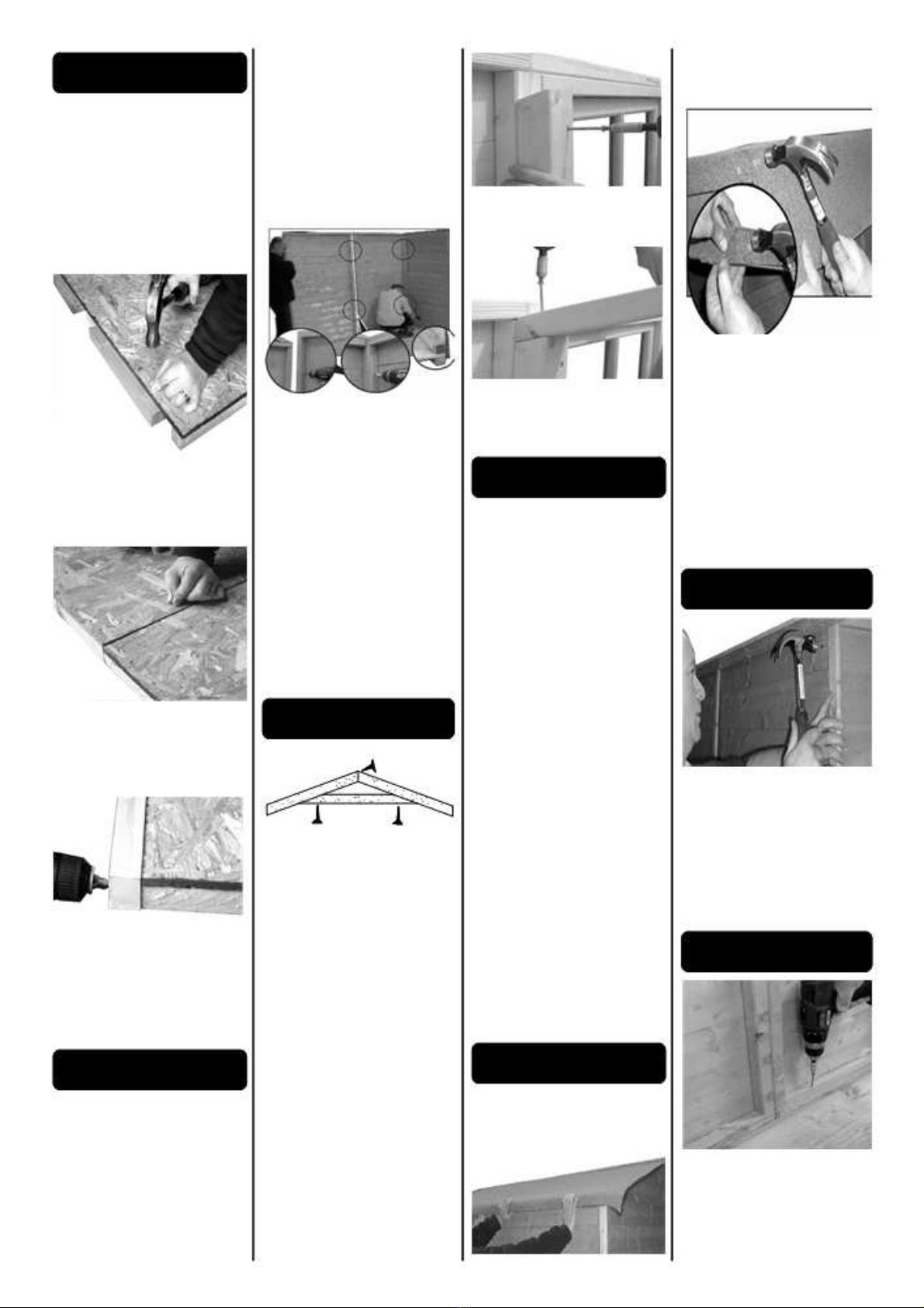
manuals.online logo
Brands
  1. Home
  2. •
  3. Brands
  4. •
  5. Shire
  6. •
  7. Garden House
  8. •
  9. Shire Workman 10x16 User manual

Shire Workman 10x16 User manual

Assembly of 10x16 Workman
Our Help Line provides support and advice to customers of
Summer Garden Buildings after ordering. For advice before
you buy you can phone us free 7 days a week on 0800
9777828 or visit www.summergardenbuildings.co.uk
Preparation of base
We recommend that the base onto which your building will stand should be at least
75mm larger in each direction than the total floor size of the building.
Actual floor area of the building: 2970x5018 mm
Total height clearance: 2168mm
The chosen position in your garden for the siting of the building should be
excavated to a depth of 75mm to allow a base of sand, on to which paving slabs can be
evenly laid - THEY MUST BE LEVEL AND FIRM.
Treatment/care of your Garden Building
Treat with a suitable decorative wood finish immediately. We recommend that all timber
pieces be treated again prior to assembly and again within 3 months of assembly. We further
recommend that all pieces are treated again at least annually or as frequently as the
instructions on the product used recommends. We would suggest that all wall panels be
TOOLS REQUIRED
●Hammer
●Step ladder
●Sand paper
●Battery-powered drill/screwdriver
●8mm drill
●Pencil
●Tape measure
●Gloves
●Sharp knife and saw
treated in an upside-down position to allow the finish/treatment to ingress into the tongue and
groove jointing. We would also remind you that you would rarely (if ever) be able to re-treat
the underside of the floor following assembly. We strongly recommend that the underside of
the floor is treated an absolute minimum of twice (not including pre-treatment).
PRESSURE TREATED buildings come to you already in a light green colour. Whilst your
pressure treated building will give you an extended life compared to non-pressure treated it is
still beneficial to apply your own choice of good quality long life preservative or stain -
although it is not absolutely necessary. Any area of timber that you cut, nail or screw after the
building arrives to you should be re-treated or stained to ensure an extended life. The light
green colouration can be stained over in your own preferred choice of colour should you
wish.
1501 345
1316
190
TRUSS BLOCK
IMPORTANT!
PLEASE READ PRIOR TO ASSEMBLY OF
THE BUILDING
EVERY PRECAUTION IS TAKEN TO
ENSURE THAT YOUR BUILDING HAS NO
ELEMENT INCORRECTLY PLACED OR
POSSIBLY HAZARDOUS, HOWEVER
TRUSS 44x44 QTY 8 TRUSS BRACE
44x44 QTY 4
1220
990 1036
ROOF PANEL ROOF PANEL ROOF PANEL
44x44 QTY 8 FLOOR JOINERS
1485
34x46 QTY 24
FLOOR EDGING
34x46 QTY 4
1625
1485
FLOOR PANEL
675
Parts List
1610
675
PRIOR TO USE PLEASE CHECK ALL
SURFACES FOR THE FOLLOWING:
1 RAISED GRAIN, SPLINTERS: sand
down timber to smooth finish
2 NAIL/SCREW/PIN HEADS PROUD: tap
home to be flush with surface of timber
3 DAMAGED SCREW HEADS
RESULTING IN SHARP SPLINTERS OF
METAL: replace
4 SHARP ENDS OF NAILS/ SCREWS/
PINS PROTRUDING THROUGH THE
PANEL: remove and reposition.
5 ENSURE ALL PARTS ARE SECURED
AGAINST REASONABLE FORCE:
remove and refit
6 ENSURE THERE ARE NO LOOSE
PARTS: remove and refit/discard
We recommend that protective
gloves be worn throughout
PLEASE NOTE
Wood is a natural product and is therefore
prone to changes in appearance, including
some warping, movement and splitting,
particularly during unusual climatic conditions
(long hot or wet spells of weather). As a natural
occurrence this is not covered by a guarantee.
QTY 2 QTY 6
641 1688
FRONT PANEL
3 SECTIONS
1485 1485
BACK PANEL
2 SECTIONS
QTY DESCRIPTION
20 Glazing 355x355mm
80 Beading 357mm
13 Cover strips 1720mm
1 Cover strip 2110mm
2 Cover strip 1889mm
4 Fascia 1740mm
2 Door stop strips 1610mm
1 Door stop strip 1360mm
QTY 2 QTY 10 DOUBLE DOORS
1717
1710
641 1980 990
DBL SIDE PANEL SIDE PANEL
QTY 2 QTY 1
1717 1710
1980 990
DBL WINDOW PANEL WINDOW PANEL
QTY 2 QTY 1
2 Diamonds 126 60mm screws
6 Door ‘T’ hinges 154 25mm screws
1 Pad bolt 8 10mm screws
2 Small barrel bolts 16 60mm nails
5 Casement stays 274 40mm nails
10 Casement staypins 430 Felt nails
10 Window hinges 160 Panel pins
4 Rolls of felt 6mtr x 1mtr
16 80mm screws
A Floor Assembly
Remove travel protection blocks
from bottom edge of panels. 1.
Ensure that your base is firm and
absolutely level.
2. Take two sections of floor and
secure together through floor
bearers (990mm side) using 3 x
60 mm screws. You will need to
turn the floor over to do this.
Repeat for other four pairs.
3. Take 6 pieces of 34x46x345
floor joiners and place between
each floor bearer. Nail half of the
widest part to the floor using 3 x 40
mm nails per piece.
4. Once floor joiners are fitted
between floor bearers, slide
another floor pair on top of floor
joiners and secure again using 3 x
40 mm nails per piece.
5. Along the front and back edge
of the completed floor fix two
34x46x1485 framework pieces.
Secure into floor bearers using 4
x 60 mm screws per framework
piece. Note: the 46mm edge sits
against the floor of the building.
B Wall Assembly
Please see truss assembly before
beginning wall assembly.
1. Pre drill panels in 3 places, top,
middle and bottom.
2. Decide which side of the build-
ing you want your window panels
to go. Place one half of the back
panel onto the floor ensuring the
cladding has overhung the floor.
Place side/window panel next to
this and join together from the
inside using 3 x 60 mm screws.
You can start with either single or
double side/window panel.
The panels along the front and
back extend from floor edge to
floor edge, the side/window
panels sit inside the front and
back panels.
3. Place other back panel half
and secure using 3 x 60 mm
screws.
4. Fit other side/window panel
next to one already in position
and secure using 3 x 60 mm
screws.
5. Place side/window panel next to
back panel and secure using 3 x 60
mm screws.
6. Place remaining side/window
panels and secure using 3 x 60
mm screws.
7. The front panels are now ready
to be placed. Secure to side panels
and to each other using 3 x 60 mm
screws per panel.
C Truss Assembly
You can use framework of back
panels as a template to construct
the truss. Lay back panels down.
1. Take the two pieces of truss
framework and the one piece of
bracing bar framework and place
together to make an ‘A’ shape.
2. Secure together at the ridge
using 1 x 60 mm screw.
3. Screw bracing bar into truss
using 1 x 60 mm screw at each
end.
4. Mark the position of the lower
angled side of the truss support
block on the back panel frame.
5. Measure from top of framework
of adjoining side panel to mark
previously made. Measure and
mark from top of framework of
adjoining side panels and centre
position of double panels. The
mark is where the lower angled
side of the truss block will be
placed.
6. Secure truss blocks in position
using 2 x 60 mm screws per
block.
7. Place the truss on top of the
two opposite support blocks and
secure using 2 x80 mm screws
per side. Repeat for other trusses
D Roof Assembly
1. Staring at the back slide one
1036x1625 mm roof panel into
position using the cut-out of the
ridge as a guide. Make sure the
panel is flush with the back of the
building and resting on one half of
the truss.
Repeat for the other side.
2. Screw roof panels together at the
ridge from the inside using 3 x 60
mm screws.
3. Secure roof panels into frame-
work of gable ends using 3 x 40
mm nails per side.
4. Place the 990x1625 mm roof
panels next to the back ones and
resting on both trusses. Secure
panels together at the ridge from
the inside using 3 x60 mm
screws. Repeat for all 990 panels.
5. Place the 1220x1625 mm
panels at the front using the cut-
out of the ridge as a guide and
resting on the truss. Secure at
ridge and into gable walls.
6. Secure panels into trusses at
the ridge using a total of 16 x 60
mm nails.
7. Secure along the length of the
building into framework of walls
using 12 x 40 mm nails per side.
E Felt Roof
1. Measure and cut the required
four lengths allowing an overhang
of approx 50 mm on all sides.
Starting at the lower edge (the
eaves) place one piece of felt
along the length of the building.
Secure the felt using felt nails
spaced at 100 mm intervals, but
do not nail along centre of
building until the piece of felt
covering the ridge is in place.
2. Place another strip along the
length of building overlapping the
first strip and overlapping the
ridge. Nail into position along both
edges of this piece and at both
ends using felt nails spaced at
approx 100 mm intervals.
Repeat for other side of roof.
F Corner Strips
1. Fix the corner strips in position
where the panels meet using 4 x
40 mm nails per strip. Place
another 1720 mm strip in the
centre of the double window
panel and centre of plain panel.
There are 3 longer cover strips,
these are for the front and back
panel joins.
G Secure Walls
1. Secure wall panels to the floor
on the inside of the building
through framework into floor
bearers using 2 x60 mm screws
per panel.
H Door Assembly
1. Place the doors on a flat level
surface, outside of door face up.
Check which side of the door the
hinges are to be fitted. The
diagonal door bracing should
point to the door opening.
2. The hinges are to be fitted onto
the boarding which covers each
horizontal door bracing. Secure in
place using 4 x 25 mm screws
per hinge.
3. To hang the doors two people
are needed, one to hold the door
level and the other to secure the
hinges. Start with the right hand
door. Place into aperture and
check for level all round. Fix 1 x
25 mm screw in each hinge first,
adjust if necessary.
Fit remaining 2 x 25 mm screws
per hinge. Repeat for other door.
4. Fit door stop strips flush to the
inside edge of the top and sides of
the door aperture. Nail in
position using 6 x 40 mm nails for
each door stop strip.
5. Fit two bolts to the inside, inner
edge of the left door. The top bolt
should be positioned so that the
solid part of the bolt finishes flush
with the top of the door. Secure
using 4 x 10 mm screws. Hold the
door tightly closed, move the
moveable part of the bolt and
mark where this meets the door
frame. Drill a small hole using an
8 mm drill bit.
6. The bottom bolt should sit flush
with the bottom edge of the door.
Fit as for top bolt.
I Pad Bolt
1. Place the pad bolt in position
on the outside of the right hand
door directly over the central
horizontal brace. Ensure the edge
is flush with the edge of the door.
Secure using 4 x 25 mm screws
using the round holes only.
2. Place pad bolt housing in
position to accommodate the pad
bolt. Secure using 2 x 25 mm
screws using the round holes
only.
3. Place outside 1720mm door
cover strip flush with the top and
bottom of the door and mark top
and bottom of pad bolt position.
4. Cut out section as marked.
5. Attach the door cover strips
above and below the pad bolt.
Half of each strip should
overhang the edge of the door and
when closed also overhang the left
hand door. Secure using 6 x 25 mm
screws.
J Window Insert
1. Place one hinge on the inner
part of the top of the window. The
rounded part of the hinge should
sit above the outer edge of the
window. Secure the inner piece
into position using 2 x 25 mm
screws. Repeat.
2. Place the window into the
aperture. Secure the window to
the panel using 3 x 25 mm
screws per hinge.
3. Open the window and fit a
further 2 x 25 mm screws per
hinge.
4. Fitting the casement stay.
Place the casement stay centrally
on the inside of the window.
Place the two pins under the
casement stay. Position so that it
is not resting on the framework of
the panel and not so high that the
pins are of no use.
5. Secure the casement stay on
the window using 2 x 25 mm
screws.
6. Mark where the pins will be
placed.
7. Secure into position using 2 x
25 mm screws per pin.
K Fascia & Diamonds
1. Nail the 4 fascia boards to
gable using 3 x 40 mm nails per
piece.
2. Nail the diamonds on top of
and in the centre of the fascia
board using 2 x 40 mm nails per
diamond.
L Glazing
1. Place glazing material into the
aperture of each window.
2. Hold into position with four
pieces of beading. Secure into
position using 2 x 15 mm panel
pins per piece of beading. Repeat
for all window apertures.
. Assembly Completion Checklist
1Check and ensure that no raised grain or splin-
ters are evident on timber components. Sand
down any raised grain or splinters using fine
grade sandpaper.
2Check that all screw, nail and pin heads are
properly tapped home and are not proud of the
timber surface.
3Check and ensure that no screws, nails or pins
protrude through any panel.
4 Check and ensure that all parts are properly se-
cured against reasonable force.
5Do not apply decorative wood finish/treatments to
wet or damp timber. Please observe the instruc-
tions of the wood finish/treatment manufacturer. 6

Other Shire Garden House manuals

Shire 6x4 Bar User manual

Shire

Shire 6x4 Bar User manual

Shire Larkspur User manual

Shire

Shire Larkspur User manual

Shire Alderney Apex User manual

Shire

Shire Alderney Apex User manual

Shire Bison Workshop User manual

Shire

Shire Bison Workshop User manual

Shire Paradise Bar User manual

Shire

Shire Paradise Bar User manual

Shire 8x8 Sun Pent Manual

Shire

Shire 8x8 Sun Pent Manual

Shire Elveden User manual

Shire

Shire Elveden User manual

Shire 4X6 Overlap 2018 User manual

Shire

Shire 4X6 Overlap 2018 User manual

Shire Abri Apex User manual

Shire

Shire Abri Apex User manual

Shire Aster 2020 User manual

Shire

Shire Aster 2020 User manual

Shire Lodge Playhouse User manual

Shire

Shire Lodge Playhouse User manual

Shire Den User manual

Shire

Shire Den User manual

Shire 7x5 Haddon 2022 User manual

Shire

Shire 7x5 Haddon 2022 User manual

Shire 46034 User manual

Shire

Shire 46034 User manual

Shire Jailhouse User manual

Shire

Shire Jailhouse User manual

Shire Salcey User manual

Shire

Shire Salcey User manual

Shire Rose Arbour User manual

Shire

Shire Rose Arbour User manual

Shire Crib Playhouse User manual

Shire

Shire Crib Playhouse User manual

Shire 10x10 Sun Pent Manual

Shire

Shire 10x10 Sun Pent Manual

Shire Flat Pack Loft User manual

Shire

Shire Flat Pack Loft User manual

Shire Garden Store User manual

Shire

Shire Garden Store User manual

Shire Casita 2016 User manual

Shire

Shire Casita 2016 User manual

Shire Highclere User manual

Shire

Shire Highclere User manual

Shire Guernsey 7x10 User manual

Shire

Shire Guernsey 7x10 User manual

Popular Garden House manuals by other brands

Waltons 12x8 COMBI SUMMERHOUSE V7 General instructions

Waltons

Waltons 12x8 COMBI SUMMERHOUSE V7 General instructions

Wolff Finnhaus Pori 28 Building instructions

Wolff Finnhaus

Wolff Finnhaus Pori 28 Building instructions

Little Cottage Value Gable Shed Assembly & instruction manual

Little Cottage

Little Cottage Value Gable Shed Assembly & instruction manual

ABSCO SHEDS 30152GK manual

ABSCO SHEDS

ABSCO SHEDS 30152GK manual

Best Barns the Meadowbrook-R 12' x 10' Assembly Book

Best Barns

Best Barns the Meadowbrook-R 12' x 10' Assembly Book

Palmako FR34-3832-3 installation manual

Palmako

Palmako FR34-3832-3 installation manual

Mercia Garden Products 03DTSHPN0806FGD1TW-V1 General instructions

Mercia Garden Products

Mercia Garden Products 03DTSHPN0806FGD1TW-V1 General instructions

Palmako FRE44-4757-1 installation manual

Palmako

Palmako FRE44-4757-1 installation manual

Palmako FR40-5050-1 installation manual

Palmako

Palmako FR40-5050-1 installation manual

Palmako EL16-1827 Assembly, installation and maintenance manual

Palmako

Palmako EL16-1827 Assembly, installation and maintenance manual

SUKKAHMART Hard Wall Aluminium 2x3m Assembly instructions

SUKKAHMART

SUKKAHMART Hard Wall Aluminium 2x3m Assembly instructions

Dunster House E3-2515SS installation manual

Dunster House

Dunster House E3-2515SS installation manual

Palmako FRC28-6132 installation manual

Palmako

Palmako FRC28-6132 installation manual

Palmako Mary FRB28-2722-1 installation manual

Palmako

Palmako Mary FRB28-2722-1 installation manual

Best Barns Hampton Assembly Book

Best Barns

Best Barns Hampton Assembly Book

Lemeks Palmako Britta FRI40-4545 installation manual

Lemeks

Lemeks Palmako Britta FRI40-4545 installation manual

Palmako EL18-4555-4 installation manual

Palmako

Palmako EL18-4555-4 installation manual

OSTO DRESDEN 34 manual

OSTO

OSTO DRESDEN 34 manual

manuals.online logo
manuals.online logoBrands
  • About & Mission
  • Contact us
  • Privacy Policy
  • Terms and Conditions

Copyright 2025 Manuals.Online. All Rights Reserved.