ShowPro K SMART PROFILE User manual

1
K SMART PROFILE
MANUAL
LEDMOV440

2
CONTENTS
SAFETY - - - - - - - - - - - - - - - - - - - - - - - - - - - - - - - - - - - - - - - - - - - - - - - - - - - - - - - - - - - - - - - - - - 3
INTRODUCTION - - - - - - - - - - - - - - - - - - - - - - - - - - - - - - - - - - - - - - - - - - - - - - - - - - - - - - - - - - - - 4
SPECIFICATIONS - - - - - - - - - - - - - - - - - - - - - - - - - - - - - - - - - - - - - - - - - - - - - - - - - - - - - - - - - - - 5
PHOTOMETRICS - - - - - - - - - - - - - - - - - - - - - - - - - - - - - - - - - - - - - - - - - - - - - - - - - - - - - - - - - - - 6
DIMENSIONS - - - - - - - - - - - - - - - - - - - - - - - - - - - - - - - - - - - - - - - - - - - - - - - - - - - - - - - - - - - - - - 7
OVERVIEW - - - - - - - - - - - - - - - - - - - - - - - - - - - - - - - - - - - - - - - - - - - - - - - - - - - - - - - - - - - - - - - - 8
INSTALLATION - - - - - - - - - - - - - - - - - - - - - - - - - - - - - - - - - - - - - - - - - - - - - - - - - - - - - - - - - - - - - 9
CONNECTION - - - - - - - - - - - - - - - - - - - - - - - - - - - - - - - - - - - - - - - - - - - - - - - - - - - - - - - - - - - - - 10
MENU - - - - - - - - - - - - - - - - - - - - - - - - - - - - - - - - - - - - - - - - - - - - - - - - - - - - - - - - - - - - - - - - - - - 12
DMX CHART - - - - - - - - - - - - - - - - - - - - - - - - - - - - - - - - - - - - - - - - - - - - - - - - - - - - - - - - - - - - - - 14
MAINTENANCE - - - - - - - - - - - - - - - - - - - - - - - - - - - - - - - - - - - - - - - - - - - - - - - - - - - - - - - - - - - - 16
TROUBLESHOOTING - - - - - - - - - - - - - - - - - - - - - - - - - - - - - - - - - - - - - - - - - - - - - - - - - - - - - - - 16

3
SAFETY
WARNING! Before carrying out any operations with the unit, carefully read this instruction
manual and keep it with care for future reference, it contains important information about the
installation, use and maintenance of the unit.
General instructions
- The products referred to in this manual conform to the European Community Directives and
are therefore marked with CE.
- The unit is supplied with hazardous network voltage (230V~). Leave servicing to skilled
personnel only. Never make any modifications on the unit not described in this instruction
manual, otherwise you risk an electric shock.
- Connection must be made to a power supply system fitted with efficient earthing (Class I
appliance according to standard EN60598-1). It is recommended to protect the supply lines
of the units from indirect contact and/or shorting by using appropriately sized residual current
devices.
- The connection to the main network of electric distribution must be carried out by a
qualified electrical installer. Check that the mains frequency and voltage correspond to those
for which the unit is designed as given on the electrical data label.
- This unit is not for home use, only use for professional applications.
- Never use the fixture under the following conditions:
• in places subject to vibrations or bumps;
• in places with a temperature of over 40 ℃.
- Make certain that no flammable liquids, water or metal objects enter the fixture.
- Do not dismantle or modify the fixture.
- All work must always be carried out by qualified technical personnel. Contact the nearest
sales point for an inspection or contact the manufacturer directly.
- If the unit is to be put out of operation definitively, take it to a local recycling plant for a
disposal which is not harmful to the environment.

4
Warnings and installation precautions
- If this device is operated in any way different to the way described in this manual, it may
suffer damage and the warranty becomes void. Any unauthorized operation may lead to
dangers like short circuit, burns, electric shock, etc.
- Before starting any maintenance work or cleaning the fixture, cut off power from the main
supply.
- Always additionally secure the fixture with a safety chain. When carrying out any work,
always comply scrupulously with all the regulations (particularly regarding safety) currently in
force in the country in which the fixture is being used.
- Install the fixture in a well-ventilated place.
- Keep any flammable materials at a safe distance from the fixture.
- Shields, lenses or ultraviolet screens shall be changed if they have become damaged to
such an extent that their effectiveness is impaired.
- The lamp (LED) shall be changed if it has become damaged or thermally deformed.
- Never look directly at the light beam. Note that fast changes in lighting, e.g. flashing lights,
may trigger epileptic seizures in photosensitive persons or persons with epilepsy.
- Do not touch the product’s housing when operating because it may be very hot.
INTRODUCTION
Features
• 600W 6000K LED engine
• 20,320 lumen output
• Extremely even spot with flawless field consistency
• CMY + CTO for precise control and smooth adjustment on colour mixing
• CRI>90 (HR filter)
• Animation wheel, adjustable frost, dual gobo wheel
• Bi-directional 4-facet prism with variable speed
• 16-bit dimming with SPWM control
• Fast, smooth Pan/Tilt movement
• DMX and RDM control

5
SPECIFICATIONS
Light source: 600W LED
Beam angle: 6°~50°
Output: 20322Lm(50°) / 12208Lm(6°)
Color temperature: 6000K
CRI: 70 / 90 (CRI filter)
LED life: 20000hrs
Pan/Tilt: 540° / 270°
Color: CMY + colour wheel (7 + open) + CTO
CTO: 3200K~6000K, linear
Gobos(rotating): 7 interchangeable + open
Animation: 1 animation wheel
Framing System: 4 independent blades (+/- 35°), rotatable (+/- 60°)
Iris: 15 leaves 10%~100% motorized linear iris
Focus: Motorized
Zoom: 6~50° (8x +)
Strobe: 0-30Hz
Dimming: 4 dimming curves, 0~100% linear dimming
Prism: Rotating bi-directional 4-facet prism with variable speed
Mains: 100~240VAC,50/60Hz
Consumption: 730W @ 230V / 782W @ 120V
Power connections: PowerCon IN/OUT
Data connections: 3pin and 5pin DMX IN/OUT
Power linking: 2pcs@230V
Data linking: up to 25pcs
Control protocol: DMX512/RDM
DMX channels: 33CH
Onboard menu: TFT display
Dimension: 355*257*593mm
Weight: 24KG

6
PHOTOMETRICS
GOBOS
COLOURS
FRAMING ANIMATION CMY
SHUTTER

7
DIMENSIONS
8
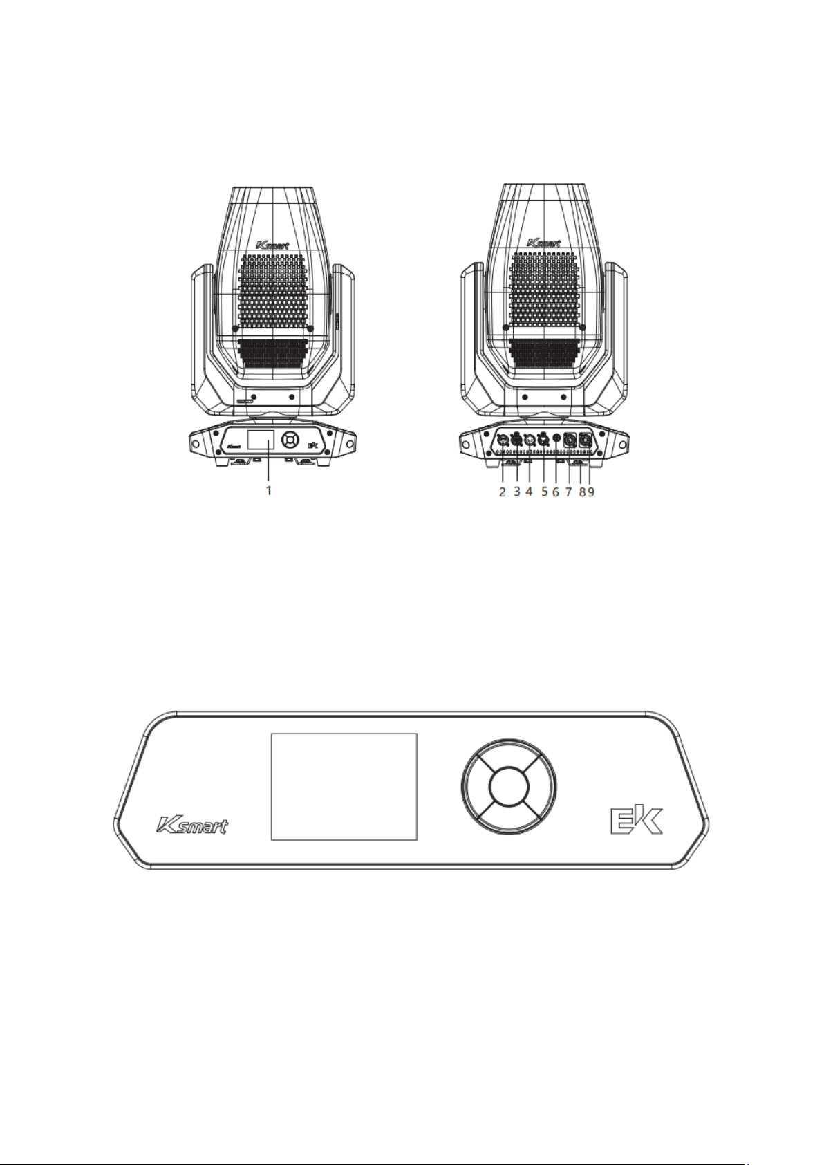
OVERVIEW
Fixture Illustration
1. Control Panel 6. Fuse
2. 3 Pin DMX In 7. PowerCon In
3. 3 Pin DMX Out 8. PowerCon Out
4. 5 Pin DMX In 9. Omega Bracket
5. 5 Pin DMX Out
Control Panel
UP:Increase value or previous menu item
DOWN: Decrease value or next menu item
LEFT: Return to top level menu
RIGHT: Select units, tens, hundreds
ENTER: Confirm, step through menu, activate display

9
INSTALLATION
The K Smart must be set up on a solid and even surface.
By means of the brackets on the baseplate, the unit can also be mounted upside down to a
cross arm. For mounting, strong, stable clamps are required.
The bolts of the brackets are placed into the openings provided in the base plate and turned
clockwise until they lock.
Always ensure that the unit is firmly fixed to avoid vibration and slipping while operating.
The mounting place must be of sufficient stability and be able to support a weight of 10 times
the unit’s weight.
When carrying out any installation, always comply scrupulously with all the regulations
(particularly regarding safety) currently in force in the country in which the fixture is being
used.
Always additionally secure the fixture with a safety chain. For this purpose, fasten the safety
chain in a suitable position so that the maximum fall of the fixture will be 20 cm.
10
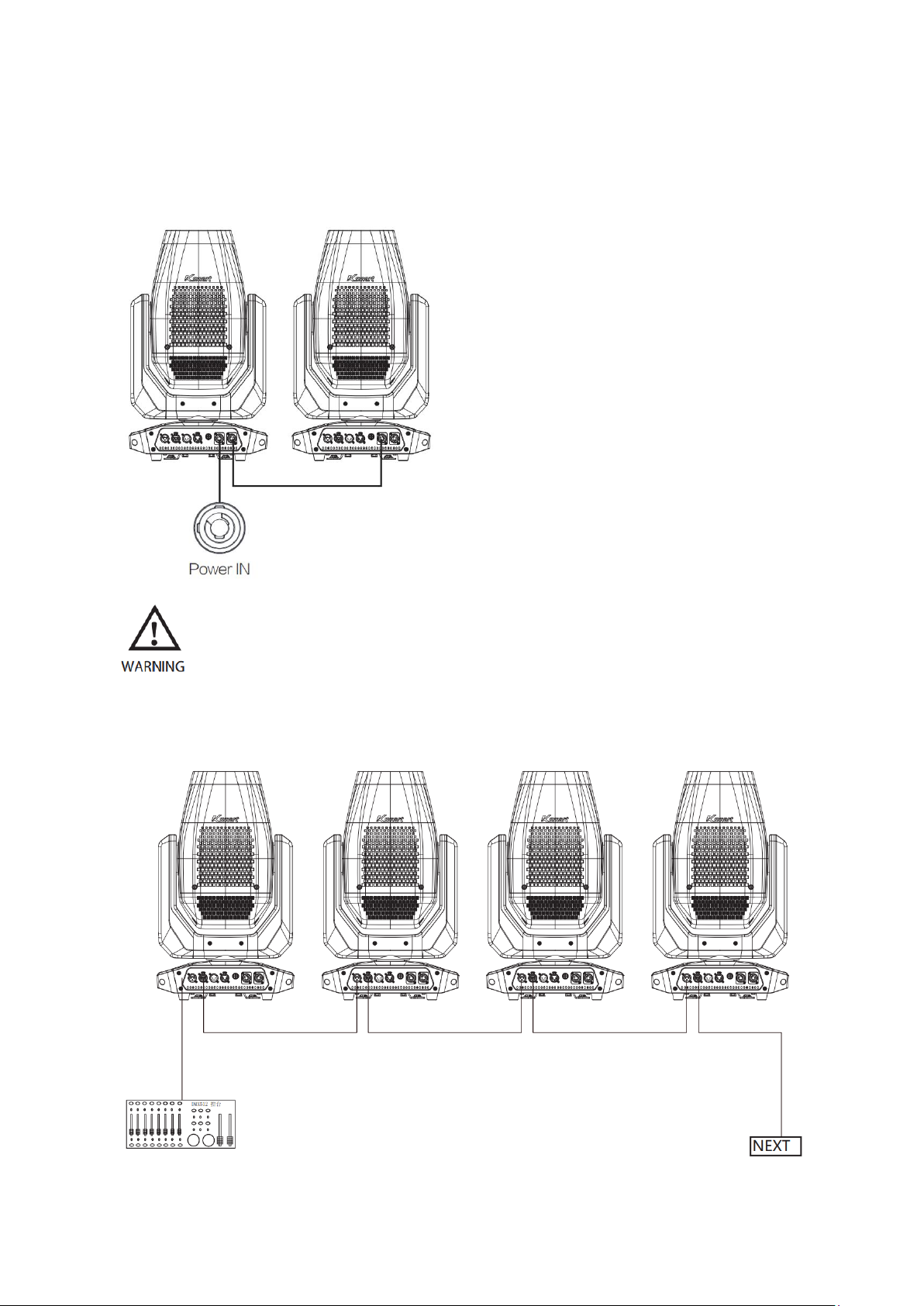
CONNECTION
Power Connection
Using PowerCon In/Out. Power cables
connected in series.
Attention: due to power rating, one power
cable can connect 2 units maximum
Do not connect more than 2 units in series with one power cable.
Do not use with damaged power cable.
Power off the fixture when not in use.
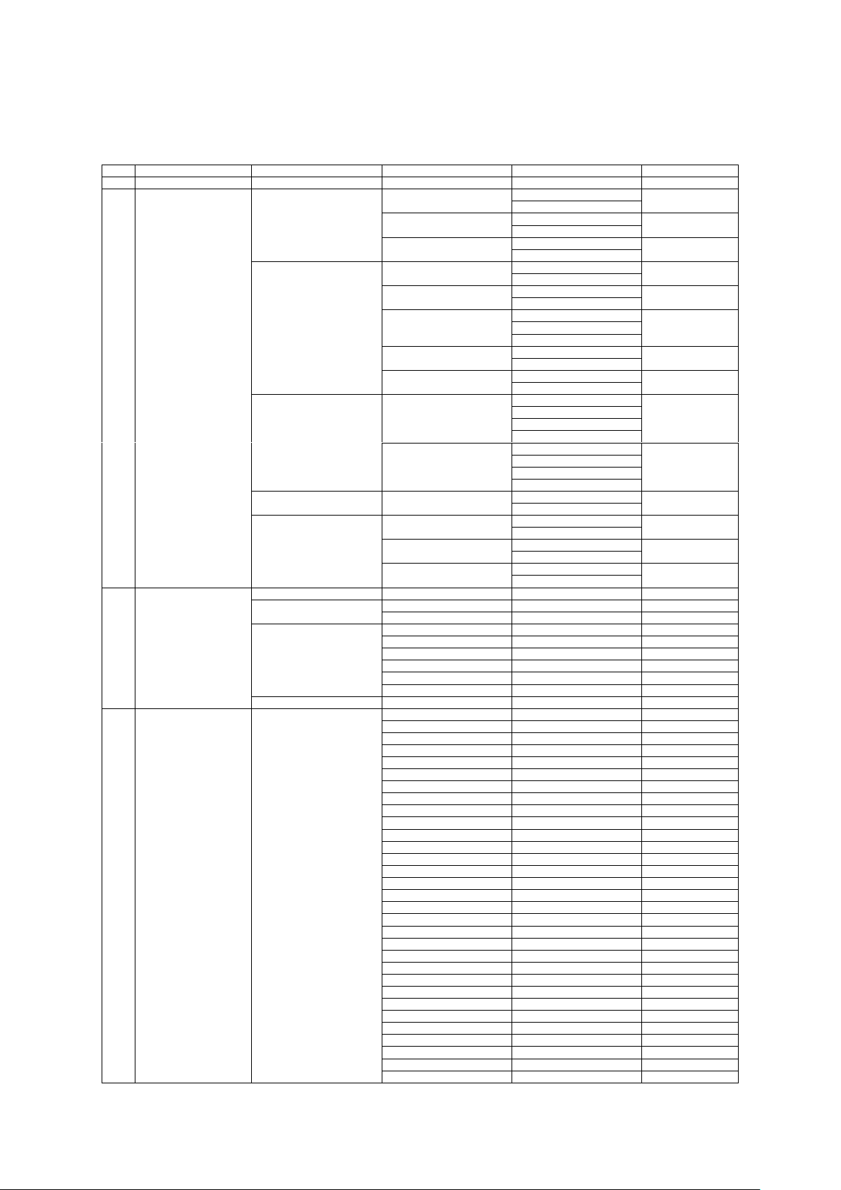
DMX Connection

11
DMX Connection
•Depending on the length of the DMX cable run, or other factors, it may be advisable
to install a terminator at the last fixture in the run.
•The illustration below shows the correct placement of a 120Ω 0.25W resistor in a
terminator, as well as the standard DMX signal pin connections
Example of DMX Addressing
The below table shows an example of starting addresses for four fixtures assuming a first
fixture with starting address of 001.
The actual starting addresses will be determined by the operator as needed to match
external controller settings.
MODE
ALLOCATION
ADDRESS
1st Fixture
ADDRESS
2nd Fixture
ADDRESS
3rd Fixture
ADDRESS
4th Fixture
33CH
001 – 033
001
034
067
100
Follow above method for subsequent fixtures, calculating addresses as indicated.
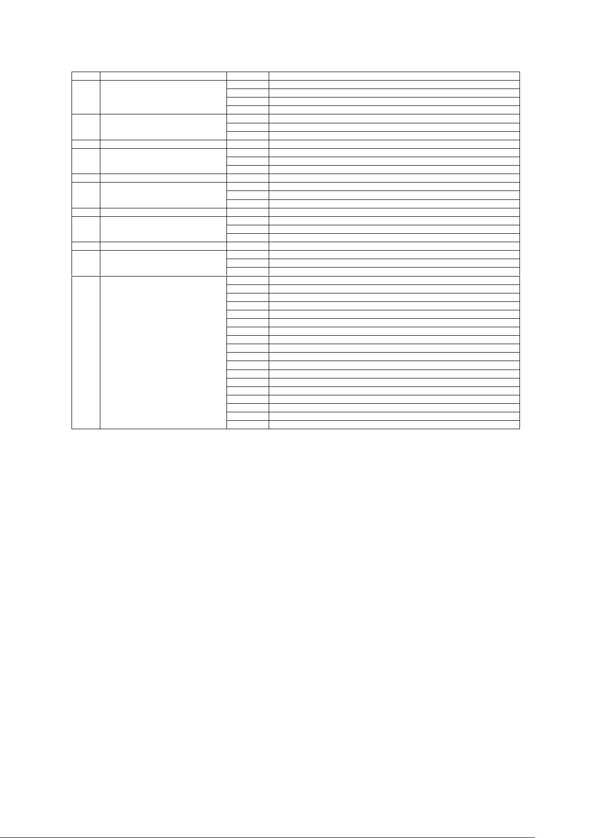
12
MENU
NO.
Main Menu
Menu Level 1
Menu Level 2
Menu Level 3
Default
1
CONNECT
DMX Address
1-480
1
2
OPTION
Movement Setting
Pan Invert
Off
Off
On
Tilt Inert
Off
Off
On
Encoder Pan/Tilt
Off
On
On
Display Setting
Warn Cue
Off
On
On
Backlight
Off
Off
On
Display Reverse
Off
Off
On
Auto
Key Lock
Off
Off
On
Temperature
°C
°C
°F
Dimmer Setting
Dimmer Mode
Off
Off
Dimmer 1
Dimmer 2
Dimmer 3
Dimmer Curve
Linear
Square
Square
Inverse Square
S-Curve
Fixture Setting
Fan Mode
Auto
Auto
Silent
Reset Setting
All
No
No
Yes
Pan/Tilt
No
No
Yes
Head
No
No
Yes
3
INFORMATION
System Errors
Time
Fixture Hours
0 – 9999H
LED Hours
0 – 9999H
System Version
DISP: V1.0
CTR1 – XY: V1.0
CTR2 – Motor: V1.0
CTR3 – Motor: V1.0
CTR4 – Motor: V1.0
CTR5 – Motor: V1.0
UID
030F06D*****
4
TEST
Channel
1.Pan
0 – 255
2.Pan Fine
0 – 255
3.Tilt
0 – 255
4.Tilt Fine
0 – 255
5.Strobe
0 – 255
6.Dimmer
0 – 255
7.Dimmer Fine
0 – 255
8.Cyan
0 – 255
9.Magenta
0 – 255
10.Yellow
0 – 255
11.CTO
0 – 255
12.Colour
0 – 255
13.Gobo
0 – 255
14.RGobo
0 – 255
15.Prism
0 – 255
16.RPrism
0 – 255
17.Frost
0 – 255
18.Focus
0 – 255
19.Focus Fine
0 – 255
20.Zoom
0 – 255
21.Zoom Fine
0 – 255
22.Effect
0 – 255
23.Iris
0 – 255
24.Shutters Rot.
0 – 255
25.Fr. Shutter 1 Move
0 – 255
26.Fr. Shutter 1 Swiv.
0 – 255
27.Fr. Shutter 2 Move
0 – 255
28.Fr. Shutter 2 Swiv.
0 – 255
29.Fr. Shutter 3 Move
0 – 255
30.Fr. Shutter 3 Swiv.
0 – 255
31.Fr. Shutter 4 Move
0 – 255

13
NO.
Main Menu
Menu Level 1
Menu Level 2
Menu Level 3
Default
4
TEST
Channel
32.Fr. Shutter 4 Swiv.
0 – 255
33.Function
0 – 255
Auto
Pan/Tilt
Colour
Beam
Gobo
Shutter
All
5
ADVANCED
(Code:050)
Calibration
Pan
0 – 255
Tilt
0 – 255
Cyan
0 – 255
Magenta
0 – 255
Yellow
0 – 255
CTO
0 – 255
Gobo
0 – 255
RGobo
0 – 255
Prism
0 – 255
RPrism
0 – 255
Frost
0 – 255
Focus
0 – 255
Zoom
0 – 255
Effect
0 – 255
Iris
0 – 255
Fr. Shutters Rot.
0 – 255
Fr. Shutter 1 M1
0 – 255
Fr. Shutter 1 M2
0 – 255
Fr. Shutter 2 M1
0 – 255
Fr. Shutter 2 M2
0 – 255
Fr. Shutter 3 M1
0 – 255
Fr. Shutter 3 M2
0 – 255
Fr. Shutter 4 M1
0 – 255
Fr. Shutter 4 M2
0 – 255
Factory Reset
No
No
Yes

14
DMX CHART
33CH
Function
Value
Setting
1
Pan
000 – 255
Pan Coarse
2
Pan Fine
000 – 255
Pan Fine
3
Tilt
000 – 255
Tilt Coarse
4
Tilt Fine
000 – 255
Tilt Fine
5
Strobe
000 – 010
No Function (Shutter Closed)
011 – 082
Shutter Effect Slow to Fast
083 – 093
No Function (Shutter Open)
094 – 163
Pulse Effect in Sequence
164 – 174
No Function (Shutter Open)
175 – 244
Random Shutter Effect Slow to Fast
245 – 255
No Function (Shutter Open)
6
Dimmer
000 – 255
Dimmer 0% - 100%
7
Dimmer Fine
000 – 255
Dimmer Fine
8
Cyan
000 – 255
Cyan 0% - 100%
9
Magenta
000 – 255
Magenta 0% - 100%
10
Yellow
000 – 255
Yellow 0% - 100%
11
CTO
000 – 255
12
Colour
000 – 007
Open
008 – 015
Open + Colour 1
016 – 023
Colour 1
024 – 031
Colour 1 + Colour 2
032 – 039
Colour 2
040 – 047
Colour 2 + Colour 3
048 – 055
Colour 3
056 – 063
Colour 3 + Colour 4
064 – 071
Colour 4
072 – 079
Colour 4 + Colour 5
080 – 087
Colour 5
088 – 095
Colour 5 + Colour 6
096 – 103
Colour 6
104 – 111
Colour 6 + Colour 7 (CRI>90)
112 – 119
Colour 7 (CRI>90)
120 – 127
Colour 7 (CRI>90) + Open
128 – 190
Fast to Slow (Forward Spin)
191 – 192
Stop (Stop Rotation)
193 – 255
Slow to Fast (Reverse Spin)
13
Gobo
000 – 003
Open
004 – 007
Gobo 1
008 – 011
Gobo 2
012 – 015
Gobo 3
016 – 019
Gobo 4
020 – 023
Gobo 5
024 – 027
Gobo 6
028 – 031
Gobo 7
032 – 045
Gobo 1 Shaking Slow to Fast
046 – 059
Gobo 2 Shaking Slow to Fast
060 – 073
Gobo 3 Shaking Slow to Fast
074 – 087
Gobo 4 Shaking Slow to Fast
088 – 101
Gobo 5 Shaking Slow to Fast
102 – 114
Gobo 6 Shaking Slow to Fast
115 – 127
Gobo 7 Shaking Slow to Fast
128 – 190
Fast to Slow (Reverse Spin)
191 – 192
Stop
193 – 255
Slow to Fast (Forward Spin)
14
RGobo
000 – 191
Positioning from 0 – 360° (Indexing)
192 – 221
Fast to Slow (Forward Spin)
222 – 225
Stop
226 – 255
Slow to Fast (Reverse Spin)
15
Effect
000 – 003
Open/No Function
004 – 127
Fast to Slow (Forward Spin)
128 – 131
Stop (Stop Rotation)
132 – 255
Slow to Fast (Reverse Spin)
16
Prism
000 – 127
Prism Out
128 – 255
Insert Prism
17
RPrism
000 – 127
Positioning from 0 – 540° (Indexing)
128 – 190
Fast to Slow (Forward Spin)
191 – 192
Stop
193 – 255
Slow to Fast (Reverse Spin)
18
Frost
000 – 255
Insert Frost, Linear
19
Focus
000 – 255
Focus Coarse
20
Focus Fine
000 – 255
Focus Fine
21
Zoom
000 – 255
Zoom Coarse
22
Zoom Fine
000 – 255
Zoom Fine
15
33CH
Function
Value
Setting
23
Iris
000 – 063
From Large to Small
064 – 127
Rapid Open/Close Slow to Fast
128 – 191
Rapid Open Slow to Fast
192 – 255
Rapid Close Slow to Fast
24
Framing Shutters Rotation
000 – 127
Rotation from Left to Centre
128
Centre
129 – 255
Rotation from Centre to Right
25
Framing Shutter 1 Movement
000 – 255
Movement outward to inward
26
Framing Shutter 1 Swivel
000 – 127
Swivel from -25° to 0°
128
0°
129 – 255
Swivel from 0° to 25°
27
Framing Shutter 2 Movement
000 – 255
Movement outward to inward
28
Framing Shutter 2 Swivel
000 – 127
Swivel from -25° to 0°
128
0°
129 – 255
Swivel from 0° to 25°
29
Framing Shutter 3 Movement
000 – 255
Movement outward to inward
30
Framing Shutter 3 Swivel
000 – 127
Swivel from -25° to 0°
128
0°
129 – 255
Swivel from 0° to 25°
31
Framing Shutter 4 Movement
000 – 255
Movement outward to inward
32
Framing Shutter 4 Swivel
000 – 127
Swivel from -25° to 0°
128
0°
129 – 255
Swivel from 0° to 25°
33
Function
000 – 020
TBD
021 – 025
Dimmer Speed Off
026 – 030
Dimmer speed Mode 1
031 – 035
Dimmer speed Mode 2
036 – 040
Dimmer Speed Mode 3
041 – 050
TBD
051 – 055
Linear
056 – 060
Square
061 – 065
Inverse Square
066 – 070
S-Curve
071 – 125
TBD
126 – 130
Fan Auto
131 – 135
Fan Silent
136 – 200
TBD
201 – 205
Complete Reset (Hold 5s)
206 – 210
Pan/Tilt Reset (Hold 5s)
211 – 215
Head Reset (Hold 5s)
216 – 255
TBD
16
MAINTENANCE
Maintenance and Cleaning the Unit
- Make sure there are no persons standing below the unit when taking down/setting up.
- Switch off the unit, unplug the main cable and wait till the unit has cooled down.
- All screws used for installing the device and any of its parts should be tightly fastened and
should not be corroded.
- Housings, fixings and installation spots (celling, trusses, suspensions) should be totally free
from any deformation.
- The main cables must be in impeccable condition and should be replaced immediately
when even a small problem is detected.
- It is recommended to clean the front at regular intervals, from impurities caused by dust,
smoke, or other particles to ensure that the light operates at maximum brightness. For
cleaning, disconnect the main plug from the socket. Use a soft, clean cloth moistened with a
mild detergent. Then carefully wipe the parts dry. For cleaning other housing parts use only a
soft, clean cloth. Never use a liquid, it might penetrate the unit and cause damage to it.
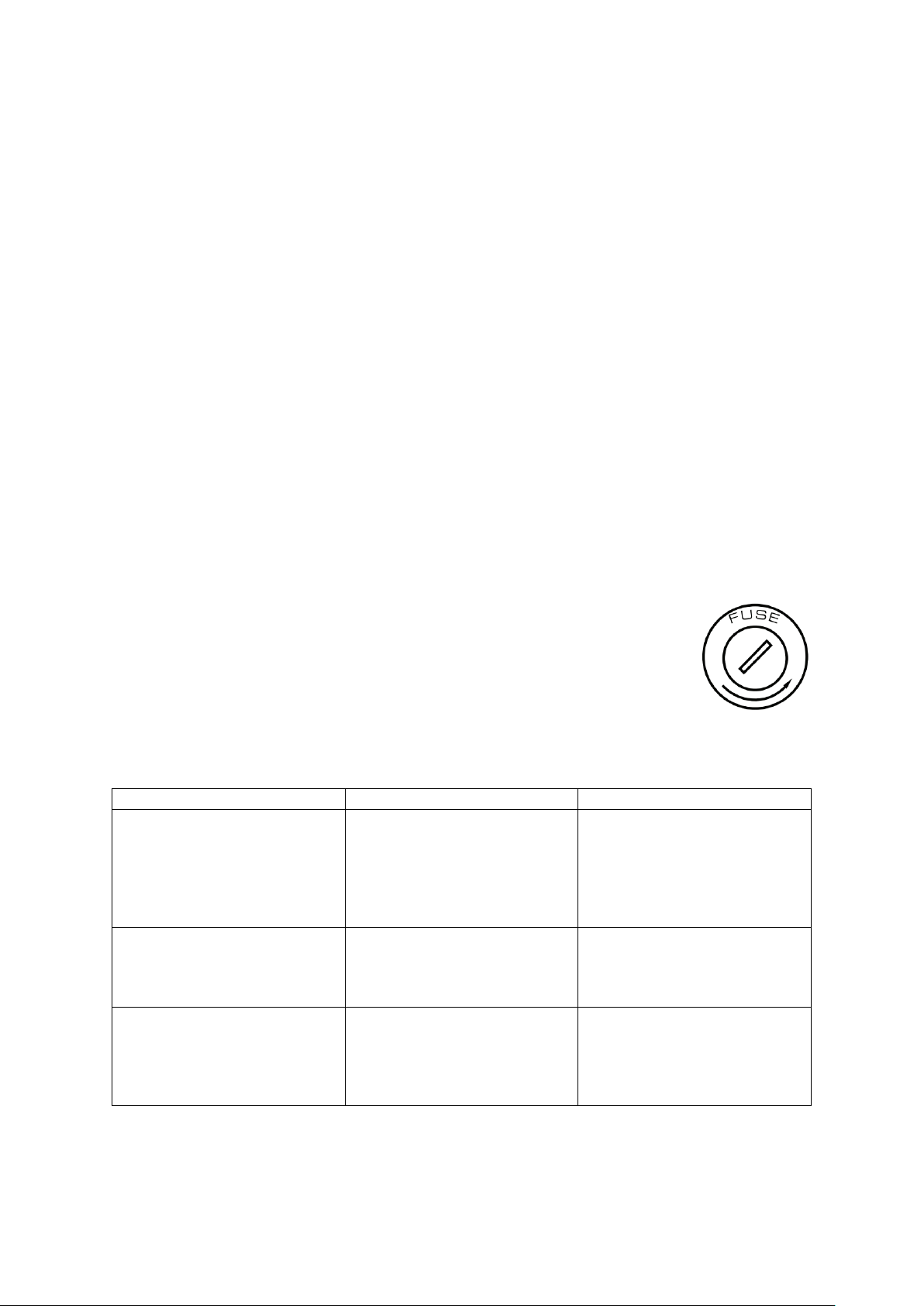
Fuse Replacement
1. Disconnect this product from the power outlet.
2. Using a screwdriver, unscrew the fuse holder cap from the housing.
3. Remove the blown fuse and replace with a good fuse of the same
type and rating (250V/T10A).
4. Screw the fuse holder cap back in place and reconnect power.
TROUBLESHOOTING
Problem
Possible Causes
Checks and Remedies
Fixture does not light up
-No mains supply
-Dimmer fader set to
0
-Faulty LED
-Faulty LED board
-Check the power
supply voltage
-Increase value of the
dimmer channels
-Replace the LED
board
General low light intensity
-Dirty lens assembly
-Misaligned LED
assembly
-Clean the fixture
regularly
-Install lens assemble
properly
Fixture does not power up
-No power
-Loose of damaged
power cord
-Faulty internal power
supply
-Check for power on
power outlet
-Check power cord
-Replace internal
power supply
Contact an authorized service centre in case of technical problems, issues not reported in
the above table, or problems that cannot be resolved by the procedure given in the table.
This manual suits for next models
1
Table of contents
Other ShowPro Dj Equipment manuals

ShowPro
ShowPro LEDMOV640 User manual

ShowPro
ShowPro LEDFRE131 User manual

ShowPro
ShowPro Hercules User manual

ShowPro
ShowPro PLUTO 2000 User manual

ShowPro
ShowPro Atomizer Pro Hazer User manual

ShowPro
ShowPro Atomizer Pro Hazer User manual

ShowPro
ShowPro LED House Light User manual

ShowPro
ShowPro ALLIGATOR User manual

ShowPro
ShowPro Pro Haze 3500 User manual

ShowPro
ShowPro NEPTUNE 200 BEAM User manual


