Manual
Rev
A MODEL
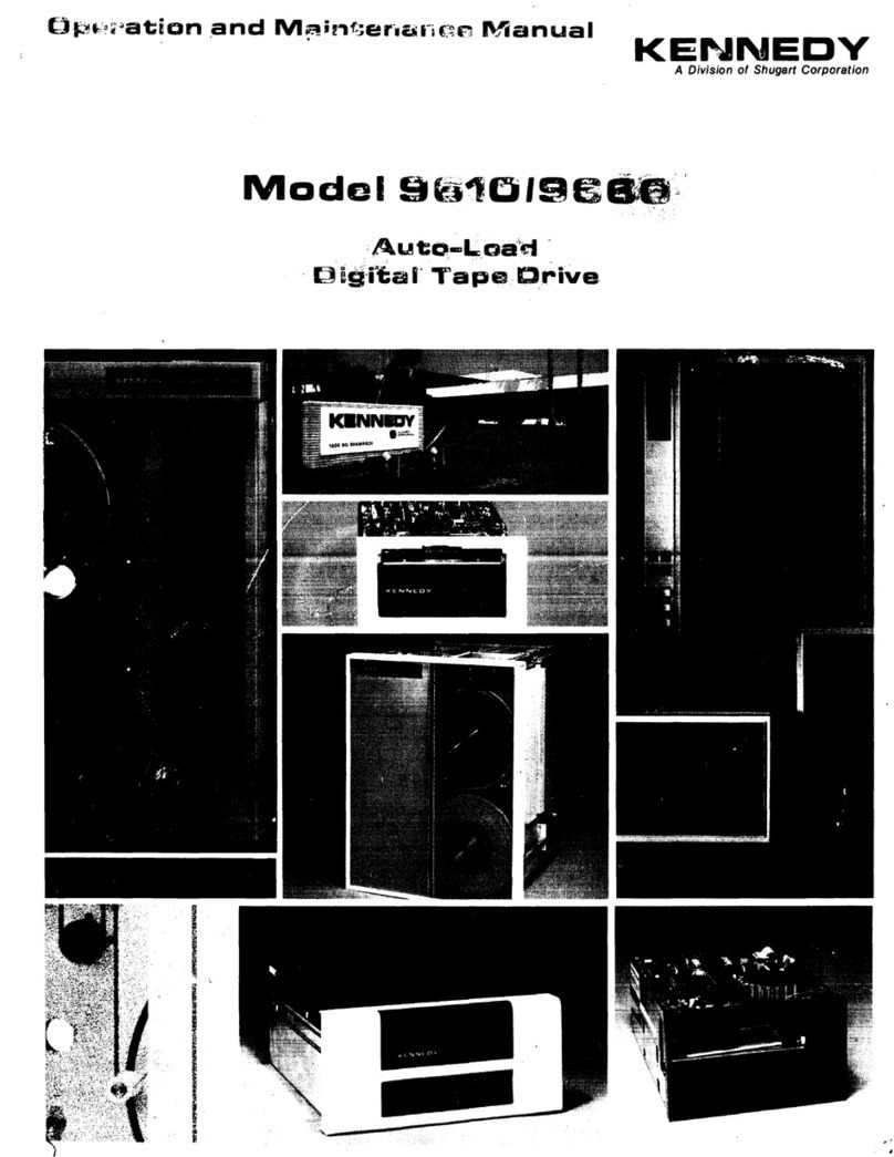
9610/9660
TAPE
DRIVE
OPERATION
AND MAINTENANCE MANUAL
TABLE
OF
CONTENTS
93-09610-004
August,
1991
SECTION I
GENERAL
DESCRIPTION AND
APPLICATION
DATA
~
Section
1.1
General
Description.
••••••••••••••••••••••••••••• 1-1
1.1.1
Host
Interface
.............................
1-1
1.1.2
Microcomputer
Based
Design
••••••••
1-1
1.1.3
Diagnostics
And
Fault
Isolation
•••••
1-1
1.2
~ecificatiollS
•••••••••••••••••••••••••••••••••••••• 1-2
1.2.1
Operational
Specifications
••••••••••
1-2
1.2.2
Physical/Environmental
Specs
•••••
1-4
1.3
Interface
Specification
.........................
1-5
1.3.1
General
••••••••••••••••••••••••••••••••••••• 1-5
1.3.2
Interface
Connectors
•••••••••••••••••• 1-5
1.3.3
Interface
Signal
Characteristics
••
1-5
1.3.4
Interface
Cables
••••••••••••••••••••••••• 1-5
1.3.5
Receiver/Driver
Configuration
••••
1-5
1.3.6
Daisy
Chaining
...........................
1-6
1.4
Interface
Input
and
Output
SignaJs
•••••••••
1-7
1.4.1
Interface
Input
Signals•••••••••••••••• 1-8
1.4.1.1
Transport
Addr,
Formatter
Addr.1-8
1.4.1.2
Initiate
Command
-
GO
•••••••••••••• 1-9
1.4.1.3
Reverse
••.•••••••••••.•••••••••••••••••••••
1-9
1.4.1.4
Write
••••••••••••••••••••••••••••••••••••••••
1-9
1.4.1.5
Write
File
Mark••••••••••••••••••••••••• 1-9
1.4.1.6
Edit
••••••••••••••••••••••••••••••••••••••••••
1-9
1.4.1.
7
Erase
••••••••••••••••••••••••••••••••••••••••
1-9
1.4.1.8
High
Speed
••••••••••••••••••••••••••••••••
1-9
1.4.1.9
Long
Gap
•••••••••••••••••••••••••••••••••• 1-9
1.4.1.10
Rewind
••••••••••••••••••••••••••••••••••• 1-10
1.4.1.11
Off-Line/Unload
•••••••••••••••••••••• 1-10
1.4.1.12
Last
Word ••••••••••••••••••••••••••••••• 1-10
1.4.1.13
Formatter
Enable
•••••••••••••••••••• 1-10
1.4.1.14
Write
Data
Lines
•••••••••••••••••••••
1-10
1.4.1.15
Load
On-Line
..........................
1-11
1.4.2
Interface
Outputs
••••••••••••••••••••• 1-11
1.4.2.1
Formatter
Busy
............
,••••••••••• 1-11
1.4.2.2
Data
Busy••••••••••••••••••••••••••••••• 1-11
1.4.2.3
Hard
Error
•••••••••••••••••••••••••••••• 1-11
1.4.2.4
Corrected
Error
(PE, DOPE)
•••••
1-11
1.4.2.5
Corrected
Error
(GCR) •••••••••••• 1-12
1.4.2.6
Check
Char
Gate
(NRZI only)
•••
1-12
1.4.2.7
Ident
Burst
(PE,
DOPE,
GCR)
•••
1-12
1.4.2.8
File
Mark
••••••••••••••••••••••••••••••••
1-12
1.4.2.9
Write
Strobe
••••••••••••••••••••••••••• 1-12
1.4.2.10
Read
Strobe
............................
1-12
1.4.2.11
Read
Data
Lines
•••••••••••••••••••••• 1-13
1.4.2.12
Ready
•.•••••••••••••••••.•••••••••••••••••
1-13
1.4.2.13
On-Line
•••••••••••••••••••••••••••••••••• 1-13
1.4.2.14
Rewinding
...............................
1-13
1.4.2.15
File
Protect
............................
1-13
1.4.2.16
Load
Point
..............................
1-13
1.4.2.17
End
of
Tape
............................
1-13
iii
1.4.2.18
Density
•••••••••••••••••••••••••••••••••••
1-14
1.4.2.19
Speed
••••••••••••••••••••••••••••••••••••••
1-14
1.4.3
Command
Execution
••••••••••••••••••
1-14
1.4.3.1
Read
Forward
••••••••••••••••••••••••••
1-15
1.4.3.2
Read
Reverse
..........................
1-15
1.4.3.3
Read
Reverse
Edit
•••••••••••••••••••
1-15
1.4.3.4
Write
••••••••••••••••••••••••••••••••••••••
1-15
1.4.3.5
Write
Edit
•••••••••••••••••••••••••••••••
1-15
1.4.3.6
Write
File
Mark •••••••••••••••••••••••
1-15
1.4.3.7
Erase
Variable
Length
••••••••••••••
1-15
1.4.3.8
Erase
Fixed
Length
••••••••••••••••••
1-15
1.4.3.9
Data
Security
Erase
•••••••••••••••••
1-15
1.4.3.10
Space
Frd,
Space
Rev
•••••••••••••••
1-16
1.4.3.11
File
Mark
Search
Fwd/Rev
•••••••
1-16
1.4.3.12
Density
Select
.........................
1-16
1.4.3.13
Scrub
••••••••••••••••••••••••••••••••••••••
1-16
1.5
Host
Interface
Timing
.........................
1-16
SECTION n INSTALLATION
AND
OPERATION
2.0
IntrOOlICtion
4o
••
4.a
•••••
*
••
$
••
=
••
:
••
e-.e.as.3e.'e
••
~.~
2-)
2.1
Unpacking
and
Packing
••••••••••••••••••••••••• 2-1
2.1.1
Unpacking
••••••••••••••••••••••••••••••••• 2-1
2.1.2
Packing
••••••••••••••••••••••••••••••••••••• 2-1
2.2
lnBI»eetion
•••••••••••••••••••••••••••••••••••••••••••
2-2
2.3
Cabling
and
Daisy
Chaining
Requirements
••••••••••••••••••••••••••••••••••••••
2-2
2.4
Installation
••••••••••••••••••••••••••••••••••••••••••
2-5
2.4.1
Table-Top
Installation
••••••••••••••••
2-5
2.4.2
Rack-Mount
Installation
•••••••••••••
2-5
2.4.2.1
Rail
Assy
Component
Checkout
••
2-5
2.4.2.2
Mounting
Procedure
••••••••••••••••••
2-5
2.5
Power-Up
and
Initial
Checkout
•••••••••••••
2-9
2.5.1
Line
Voltage
••••••••••••••••••••••••••••••
2-9
2.5.1.1
AC
Line
Voltage
•••••••••••••••••••••••
2-9
2.5.1.1.1
Single
Fuse
Power-In
••••••••••••••
2-9
2.5.1.1.2
Dual
Fuse
Power-In
•••••••••.•••••
2-10
2.5.1.2
DC
Line
Voltage
••••••••••••••••••••••
2-11
2.5.2
Power-Up
•••••••••••••••••••••••••••••••••
2-11
2.5.3
Checkout
••••••••••••••••••••••••••••••••••
2-11
2.5.3.1
Loading
Tape
•••••••••••••••••••••••••••
2-11
2.5.3.2
Load
Details
••••••••••••••••••••••••••••
2-11
2.5.3.3
Checkout
Continued
•••••••••••••••••
2-12
2.5.3.4
Motion
Test
Summary
••••••••.•••••.
2-13
2.5.4
Unit
Selection
•••••••••••••••••••••••••••
2-13
2.5.5
Data
Density
-
Introduction
•••••••
2-15
2.6
()perating
Instructions
•••••••••••••••••••••••••
2-17
2.6.1
Operating
Procedure
••••••••••••••••.
2-17
2.6.2
Operation
Notes
••••••••••••••••••••••••
2-17
