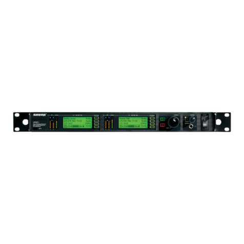
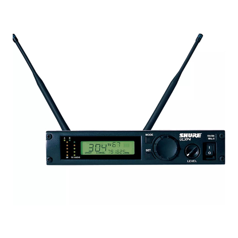
Shure PSM 900 User manual

© 2014Shure Incorporated
Printed in U.S.A.
27B16401 (Rev. 2)
PSM®900
Personal Monitor Wireless System
PSM
®
900 ワイヤレスパーソナルモニターシステム
PSM®900 무선 개인 모니터 시스템
PSM®900 个人无线监听系统
*27B16401*

ii

iii
WARNING!
LISTENING TO AUDIO AT EXCESSIVE VOLUMES CAN CAUSE PERMANENT HEARING
DAMAGE.
USE AS LOW A VOLUME AS POSSIBLE.
Over exposure to excessive sound levels can damage your ears resulting in permanent noise-
induced hearing loss (NIHL). Please use the following guidelines established by the Occupational
Safety Health Administration (OSHA) on maximum time exposure to sound pressure levels before
hearing damage occurs.
90 dB SPL
at 8 hours
95 dB SPL
at 4 hours
100 dB SPL
at 2 hours
105 dB SPL
at 1 hour
110 dB SPL
at ½ hour
115 dB SPL
at 15 minutes
120 dB SPL
Avoid or damage may occur
SAFETY PRECAUTIONS
The possible results of incorrect use are marked by one of the two symbols
- “WARNING” AND “CAUTION” - depending on the imminence of the danger
and the severity of the damage.
WARNING: Ignoring these warnings may cause severe injury or death
as a result of incorrect operation.
CAUTION: Ignoring these cautions may cause moderate injury or prop-
erty damage as a result of incorrect operation.
WARNING
• If water or other foreign objects enter the inside of the device, fire or
electric shock may result.
• Do not attempt to modify this product. Doing so could result in personal
injury and/or product failure.
CAUTION
• Never disassemble or modify the device, as failures may result.
• Do not subject to extreme force and do not pull on the cable or failures
may result.
• Keep the microphone dry and avoid exposure to extreme temperatures
and humidity.
WARNING: This product contains a chemical known to the State of California to cause cancer and
birth defects or other reproductive harm
極端に大きな音量で再生すると、慢性の聴力障害の原因となる恐れがあります。
できるだけ小さな音量で使用してください。
警 告 !
極端に大きな音を長時間聞き続けると、耳を痛める原因となり、
慢性的な騒音性聴力障害(NIHL)を引き起こす恐れがあります。
聴覚を損なわないようにするため、各音圧に耐えられる最長限度時間に関して
米国労働安全衛生庁(OSHA)が定めたガイドラインを以下に記載します。
90 dB SPL
8時間
95 dB SPL
4時間
100 dB SPL
2時間
105 dB SPL
1時間
110 dB SPL
30分
115 dB SPL
15分
120 dB SPL
回避しないと耳を痛める原因となります
지나치게 볼륨을 높여서 오디오를 들을 경우 영구적인 청력 손상을 입을 수 있습니다.가능한 낮은
볼륨으로 사용하십시오.
경고 !
지나치게 높은 소리로 장시간 사용하면 청력을 손상시켜 영구적인 소음성 난청을 유발 할 수
있습니다. 미국 산업안전보건청(OSHA): Occupational Safety Health Administration) 기준에
따르는음압레벨에따라청력손상이발생하지않도록최대노출시간에대한다음지시사항을
따르십시오.
90 dB SPL
8시간
95 dB SPL
4시간
100 dB SPL
2시간
105 dB SPL
1시간
110 dB SPL
30분
115 dB SPL
15분
120 dB SPL
금지, 그렇지 않으면 손상 발생 가능
收听时音量过高可能导致听力永久性损伤。应尽可能降低音量。
警告!
长期暴露在过高音量下,可能会导致噪音引起的听力受损(NIHL)。对于在髙声
压级时听音的最长时间,应遵循美国职业安全与健康部(OSHA)制定的指导原
则,以避免听力受损。
90 dB SPL
8小時
95 dB SPL
4小時
100 dB SPL
2小時
105 dB SPL
1小時
110 dB SPL
半小時
115 dB SPL
15分钟
120 dB SPL
应避免,否则会导致听力受损
安全にお使いいただくために
危険や損害の大きさと切迫の程度を明示するために、誤った扱いをすると生じることが想定される内
容を次の定義のように「警告」「注意」の二つに区分しています。
警告: この表示内容を無視して誤った取り扱いをすると、死亡または重傷を負う
可能性が想定される内容です。
注意: この表示内容を無視して誤った取り扱いをすると、傷害を負う可能性また
は物的損害が発生する可能性が想定される内容です。
警告
• 水や異物が入ると火災や感電の原因となります。
• 本製品の改造は試みないでください。 改造した場合には怪我や製品故障の原因となります。
注意
• 分解・改造は故障の原因となりますので絶対におやめください。
• 無理な力を与えたり、ケーブルを引っ張ったりしないでください。故障の原因となり
ます。
• マイクロホンは濡らさないようにしてください。極度の高温・低温や湿気にさらさないでください。
안전 유의 사항
잘못된사용으로발생할수있는결과는위험의절박한정도나피해의심각성에
따라,
“경고”나“주의”두가지기호중하나로표시하였습니다.
경고:이경고를무시하면올바르지못한작동의결과로심각한부상이나사
망이유발될수있습니다.
주의:이주의를무시하면올바르지않은동작의결과로가벼운부상이나재
산상의손실이유발될수있습니다.
경고
• 물이나이물질이기기내부에들어가면화재나감전을초래할수있습니다.
• 이제품을개조하려고시도하지마십시오.상해를입거나제품이고장을
일으킬수있습니다.
주의
• 고장을일어날수있으므로기기를절대로분해하거나개조하지마십시오.
• 과도한충격을가하거나케이블을잡아당기지마십시오.고장이일어날수
있습니다.
• 마이크를건조한상태로유지하고고온이나습도에노출시키지마십시오.
安全事項
根據危險程度和損壞嚴重性的不同,使用“警告”和“小心”對未正確使用可能導致的
後果做出標識。
警告:如果沒有遵循這些警告事項,在操作不正確的情況下可能會導致嚴重
的人身傷亡事故。
小心:如果未遵循這些小心事項,在操作不正確的情況下可能會導致常見的
人身傷害或財產損失。
警告
• 如果有水或其他異物進入設備內部,可能會導致起火或觸電事故。
• 不要嘗試改裝本產品。這樣做會導致人身傷害和/或產品故障。
小心
• 不要拆開或改裝設備,這樣可能會導致故障。
• 不要用力過大,不要拉扯纜線,否則會導致故障。
• 應讓話筒保持乾燥,並避免暴露在極高的溫度和濕度下。

iv

1
PSM900
Features
Superb audio quality
• Digital stereo encoder provides a wider stereo field
with exceptional separation, enhancing audio detail
and clarity
• Patented Audio Reference Companding sounds more
like wired
• Available with Shure SE425 Sound Isolating™
Earphones featuring dual high-definition MicroDrivers
for accurate and balanced audio response
Robust RF Performance
• Precision front-end RF filtering for a cleaner, stronger
RF signal and fewer dropouts and audible artifacts.
• Exceptional transmitter linearity vastly reduces
frequency intermodulation, allowing more channels
per frequency band.
• Automatic RF gain control prevents signal distortion
due to RF overload.
Advanced Setup and Operation
• Patent-pending CueMode allows monitoring of the
stage mixes of up to 20 separate transmitters from
one bodypack.
• Front panel RF mute switch for disabling RF
transmission during setup
• Scan and Sync setup identifies the best group and
channel for your system and assigns it over a wireless
IR link
• MixMode®Technology allows the bodypack user to
adjust their own onstage monitor mix
• High-frequency EQ boost on bodypack
Components
menu
Rackmount supplies
①Shortrackear
②Longrackear
③Linkbartomounttosimilarrackunit
④2antennaholeplugs
⑤8rackearscrews
⑥4rackmountscrewswithwashers
⑦Extensioncablesandconnectorsforfront-mountingantennas
①
②
③
④
⑤
⑥
⑦
• P9T: Rack Unit Transmitter • P9RA: Bodypack Receiver
• PS41: Power supply • Protective bumpers with 8 screws
The PSM 900 Wireless Personal Monitor System from Shure offers an unprecedented combination of superb audio quality, robust RF performance, and category-leading setup
features for the most demanding professional applications. All new, patent-pending CueMode allows the sound engineer to monitor different stage mixes with the touch of a
button. Precision front-end RF filtering significantly reduces dropouts from RF interference, and the enhanced digital stereo encoder provides excellent stereo separation and
audio clarity.

2
ACADAPTER
50 - 60 Hz
OUTPUT:15 V 600 mA Max.
IV
EFFICIENCYLEVEL
MADEIN CHINA
RISKOF ELECTRIC SHOCK,
DONOTOPEN.
DRY LOCATION USE ONLY.
CAUTION
250mA Max.
INPUT:100 - 240 V
TÜVRheinlandGroup
I
D
:
1
0
0
0
0
0
0
0
0
0
menu
www.shure.com
A
A
AA
A
1. 2.
3.
5.
4.
6.
1. 2.
3. 4.
5.
Quickstart Instructions
Rack Mount Transmitter
1. Connect to a power outlet using the supplied power cable.
2. Attach the supplied antennas to the antenna out BNC connectors.
3. Connect the audio source, such as the output of a mixer, to the audio inputs.
You can use both input jacks or choose either one for a mono source.
4. Switch RF off and power on.
5. For mono (one input), access the Audio menu and select Mono.
Set the input sensitivity to match the source using the Util > Audio > INPUT
setting.
6. Adjust the audio source level so that, for the average input signal level, the top
two yellow LEDs flicker and the lower LEDs are solid. If the red clip LED illumi-
nates and a warning appears on the LCD, the inputs are overdriven. Decrease
the audio input level to +4 dBu from the Audio menu. If the signal level is too
low, change the input sensitivity to –10 dBV
Bodypack
Open by pressing the latches on both sides and pulling. Insert the batteries or
battery pack and attach antennas. Turn on using the volume knob. The battery
light illuminates.
Scan and Sync
1. On the bodypack, press the scan button. The display flashes SYNC NOW....
2. Align the IR windows on the bodypack and rack unit, the IR window on the
transmitter illuminates. Press the sync button on the transmitter. The rack
unit Level LEDs flash, and the screen displays SYNC SUCCESS.
3. Turn the RF switch on. The blue RF LED illuminates on the bodypack to
indicate that it is detecting the transmitter. The bodypack also displays the
RF signal strength (RF).
4. Important: Turn bodypack volume down before plugging in earphones.
5. Insert the earphones and slowly turn up the volume.
Important: Remove the protective film from the face of the transmitter or the IR
sync may not work.

3
Rack Unit Transmitter
Front Panel Controls
① Input Level Control and Display
Usethe▼▲buttonstoadjusttheaudiosothat,fortheaverageinputsignallevel,
the top two yellow LEDs flicker and the lower LEDs are solid. The red clip LED
indicates the inputs are overdriven. Reduce the level at the audio source or
change the input sensitivity of the rack unit from the AUDIO > INPUT menu.
② Status Display and Menu Controls
Use the enter and exit buttons and the menu wheel to access the configuration
menu. Push the menu wheel to move the cursor to the next item. Turn the menu
wheel to change a parameter—the enter button flashes. Press it to save the
value. Press the exit button to cancel changes and return to the previous menu.
③ Synchronization Button
Press the sync button while rack unit and bodypack IR windows are aligned to
transfer settings.
④ Headphone Monitoring
The volume control adjusts signal output to the 3.5 mm headphone jack. NOTE:
it does not affect rear panel outputs.
⑤ RF switch
Mutes RF output. For setting up multiple systems or adjusting settings without
transmitting unwanted RF or audio signals.
⑥ Power Button
Turns the unit on and off.
Rear Panel Connectors
⑦ Power
Connect the transmitter to a power outlet using the supplied power adapter.
⑧ LOOP OUT
Sends a copy of the audio signal going into the transmitter to another de-
vice. See LOOP Applications.
⑨ Audio Inputs
Connect to balanced or unbalanced outputs. Use either connector for mono
input. Accepts both 1/4-inch or male XLR connectors.
⑩ Antenna (BNC)
Attach supplied antenna. If you are rack mounting, use a front panel or re-
mote mounting kit from Shure.
level L R menu sync volume power
CLIP
sync
Configuration Menu
Note: Configuration menu items may vary with regional model variations.
Audio Settings
AUDIO > MODE
Selects monitor mode
STEREO/MX
Transmits both channels
MONO
Transmits a mono signal to
bodypack
AUDIO > INPUT
Sets nominal input level
LINE +4 dBu
line level
AUX -10dBV
aux level
RF Settings
RADIO
G
Sets the group number
CH
Sets the channel number
888.888MHz
Manual frequency selection
RF POWER
Select from 10, 50, or 100 mW
(varies by region)
Utilities and Display Settings
UTILITIES
EDIT NAME
Changes the name on the LCD display (this name
is uploaded to the bodypack with sync)
DISPLAY
Changes the display format
CONTRAST
Changes the display contrast
CUSTOM GROUP
For creating custom frequency groups
UTILITIES > LOCK PANEL
Locks front panel controls. To unlock, press exit, select
OFF, and press enter.
MENU+LEVEL
Locks menu and level controls.
MENU ONLY
Locks only the configuration menu (menu controls).
MENU+SWITCH
Locks all controls except for the level buttons (in-
cluding the RF and power switches).*
ALL
Locks all controls (including the RF and power
switches).*
*RF is automatically activated when locked. When you
unlock the unit, RF and power turns off if the swithes
are off.
UTILITIES > RX SETUP
These settings are sent to the bodypack during a sync (when the sync
direction is from the transmitter). The default KEEP parameter will not
change the bodypack settings.
LOCK
Lock bodypack
V LIMIT
Volume limiter
LIM VAL
Volume limiter value
MODE
Stereo (ST) or MixMode (MX)
BAL MX
CH. 1 (L) and CH. 2 (R) mix for MixMode
BAL ST
Left (L) and right (R) balance for stereo mode
HIBOOST
high frequency boost
UTILITIES > RESET SYSTEM
Returns all settings to the factory defaults
NO
Exit and do not reset system.
YES
Reset system settings.

4
Bodypack Receiver
① Power Switch and Volume Control
Turns the bodypack on and off and adjusts earphone volume.
② 3.5 mm Earphone Jack
Insert earphones here.
③ Scan Button
Press the scan button to find an available frequency. Press and hold for two sec-
onds to find the group with the most available channels.
④ IR Window
For transmitting settings between bodypack and rack unit.
⑤ Battery Compartment
Requires 2 AA batteries or Shure rechargeable battery. Open by pressing the
latches on both sides and pulling.
⑥ Menu buttons
Useinconjunctionwiththe▼▲buttonstoaccesstheconfigurationmenus.
⑦ ▼▲ Buttons
Use to adjust the audio mix (in MixMode only), or in conjunction with the menu
buttons to change settings.
⑧ LCD Screen
Displays current settings and menus.
⑨ Tri-Color Battery LED
Illuminates green, amber, or red to indicate battery power. When red, change
battery immediately.
⑩ Blue RF LED
Indicates the bodypack is receiving a signal from the transmitter.
⑪ SMA Connector
For detachable antennas.
⑫ Removable AA Adapter
Remove to use with a Shure SB900 rechargeable battery.
Battery Indicator Tri-Color
Battery LED
Approximate Hours Remaining (h:mm)
Alkaline Shure SB900 Rechargeable Battery
Volume Level Volume Level
468468
Green 6:00 to 3:50 4:20 to 2:45 3:15 to 2:05 8:45 to 4:00 7:15 to 4:00 6:25 to 4:00
Green 3:50 to 2:50 2:45 to 2:00 2:05 to 1:30 4:00 to 3:00 4:00 to 3:00 4:00 to 3:00
Green 2:50 to 1:15 2:00 to 1:00 1:30 to 0:50 3:00 to 2:00 3:00 to 2:00 3:00 to 2:00
Green 1:15 to 0:25 1:00 to 0:20 0:50 to 0:20 2:00 to 1:00 2:00 to 1:00 2:00 to 1:00
Amber 0:25 to 0:15 0:20 to 0:10 0:20 to 0:10 1:00 to 0:30 1:00 to 0:30 1:00 to 0:30
Red < 0:15 < 0:10 < 0:10 < 0:30 < 0:30 < 0:30
Total Battery Life 6:00 4:20 3:15 8:45 7:15 6:25
A
Battery Life
Note: Battery life using Energizer brand AA Alkaline batteries and the following conditions:
• Receiver audio set to HIBOOST = OFF and V LIMIT = OFF
• Transmitter audio INPUT set to Line+4 dBu and Levelsetto−9dB
• Audio input to the transmitter: pink noise at +8.7 dBV
• Audiooutputatreceiver:115dBSPLinearwithSE425earphones(impedenceat22Ώ)setatvolumelevel4.
Note: Using lower-impedance earphones or ones with different sensitivity, different battery types, and higher gain settings in the PSM system may cause
the receiver battery life to be different than specified.
Pink noise is a signal with a frequency spectrum such that the power spectral density is inversely proportional to the frequency. In pink noise, each octave
carries an equal amount of noise power.
Note: To remove adapter, open door and slide out. To reinstall adapter, place
over the clip and press, there will be an audible click when seated.

5
Configuration Menu
Audio Settings
Access the following audio settings from the Audio menu.
MODE
Output Mode
STEREO
Stereo
MIXMODE
MixMode
HIBOOST
High-Frequency EQ Boost
OFF
No boost (flat).
4 dB
4 dB boost at 10 kHz.
2 dB
2 dB boost at 10 kHz.
V LIMIT
Volume Limiter
V LIMIT
Turns limiter on (ON) or off (OFF) .
VALUE
3 to 9: analogous to volume knob position (for example, 5
is equal to the 5th dot on the volume knob).
BAL ST / BAL MX
Balance
▼▲ Buttons
Left and right balance for earphones when in stereo mode,
or mix of left and right channel for MixMode
GAIN
Output Gain
HIGH
Increases gain by 10 dB
STANDARD(STD)
0 dB of gain.
Utilities and Display Settings
Access the following settings from the UTILITIES menu.
UTILITIES
CUEMODE
Enters CUEMODE (to exit, press enter and select EXIT CUEMODE)
DISPLAY
Change the display settings on the bodypack
CONTRAST
Sets display brightness to high, low, or medium.
LOCK PANEL
Locks all controls except power and volume.To unlock, press exit,
select OFF, and press enter.
BATTERY
Displays the following: Hrs: Min Left, temperature, Status, Cycle
Count, and Health.
RESTORE
Returns receiver to factory default settings.
RF Settings
Access the following RF settings from the RADIO menu.
RADIO
G:
Group number. Each group contains channels selected to work well
together in a single installation.
CH:
Channel number. Sets the receiver to a channel in the selected
group.
888.888 MHz
Displays the frequency to which the receiver is set. Highlight and
usethe▼▲buttonstosettoaspecificfrequency.
SQUELCH
Adjusts the squelch setting.
RF PAD
Attenuates antenna signals in 3 dB increments.

6
Multiple System Setup
When setting up multiple systems, designate a single bodypack to scan for available
frequencies and download them to all the rack units.
The bodypack must be from the same frequency band as all the transmitters.
1. Power on all the rack units. Turn off the RF. (This prevents them from interfering
with the frequency scan.)
Note: Turn on all other wireless or digital devices as they would be during the
performance or presentation (so the scan will detect and avoid any interferance
they generate).
2. Use the bodypack to scan for a group by pressing and holding the scan button
for two seconds. The bodypack displays the group and the number of available
channels, and flashes SYNC NOW....
Important: Note the number of available channels. If you have more rack units
than available channels, eliminate potential sources of interference and try again,
or call Shure Applications for assistance.
3. Sync the bodypack with the first rack unit by aligning the IR windows and pressing
sync.
4. Press scan again on the bodypack to find the next available frequency.
5. Sync the bodypack with the next rack unit.
6. Repeat with all the rack units.
7. Sync each performer's bodypack to its respective rack unit by aligning the IR win-
dows and pressing snyc. DO NOT press scan on the bodypacks.
8. Turn on the RF on all rack units. The systems are ready to use.
CueMode
CueMode allows you to upload the name and frequency settings from multiple rack
units and store them as a list on a single bodypack. You can then, at any time, scroll
through that list to hear the audio mix from each transmitter, just as each performer
does during a show.
CueMode lists are retained even if CueMode is exited, the bodypack is turned off, or
batteries are removed.
Note: Set the channel frequency and assign display names for each transmitter be-
fore creating your CueMode list.
Adding Transmitters to the CueMode List
Note: The transmitter must be from the same frequency band as the bodypack.
1. Open the battery door and press the enter button.
2. From the main menu, scroll to UTILITIES and press enter. Select CueMode and
press enter again.
3. Align IR windows and press sync on the rack unit.
The LCD displays SYNC SUCCESS after frequency and name data are uploaded
to the CueMode list. It also displays the CueMode number for that transmitter and
the total number of transmitters.
4. Repeat the above step for each transmitter.
Note: Syncing while in CueMode does not change any of the settings on the
bodypack.
Auditioning Mixes
1. Enter CueMode from the UTILITIES menu.
2. Usethe▼▲buttonstoscrollthroughyourCueModelisttohearthemixes.
Exiting CueMode
Exit CueMode by pressing enter and selecting EXIT CUEMODE.
Managing CueMode Mixes
While in Cue Mode, you can access the following menu by pressing enter:
REPLACE MIX: Select and press sync on a rack unit to upload new data for the
current mix (for example, if you have changed the transmitter frequency).
DELETE MIX: Removes the selected mix.
DELETE ALL: Removes all mixes.
EXIT CUEMODE: Exits CueMode and returns the bodypack to the previous fre-
quency setting.
Frequency Scan
Use a frequency scan to analyze the RF environment for interference and identify
available frequencies.
• Channel Scan Press the scan button on the bodypack. Finds the first available
channel.
• Group Scan Press and hold the scan button for two seconds. Finds the group
with the greatest number of available channels. (Each group contains a set of
frequencies that are compatible when operating multiple systems in the same
environment.)
Note: When performing a frequency scan:
• Turn off the RF on the transmitters for the systems you are setting up. (This
prevents them from interfering with the frequency scan.)
• Turn on potential sources of interference such as other wireless systems or
devices, computers, CD players, large LED panels, effects processors, and digital
rack equipment so they are operating as they would be during the presentation or
performance (so the scan will detect and avoid any interference they generate).
Sync
You can transfer frequency settings in either direction: from the bodypack to the rack
unit, or from the rack unit to the bodypack.
Note: You can also choose to transfer other settings to the bodypack during a
sync, such as lock or mode settings, using the Sync > RxSetup menu on the rack
transmitter.
Downloading settings from the bodypack
1. Press the scan button on the bodypack.
2. Align the IR windows and press the sync button from the rack transmitter LCD
menu while the bodypack display is flashing "SYNC NOW...".
The level LEDs on the rack unit flash.
Sending settings to the bodypack
1. Press the Sync button on the rack transmitter to access the sync menu.
2. Align the IR windows.
When properly aligned the IR window on the transmitter illuminates.
3. Press Sync to transfer settings
The blue LED on the bodypack flashes.
7
Squelch
Squelch mutes audio output from the bodypack when the RF signal become noisy.
While squelch is activated, the blue LED on the bodypack turns off.
For most installations, squelch does not need adjustment, and it keeps the performer
from hearing hiss or noise bursts if the RF signal becomes compromised. However,
in congested RF environments or in close proximity to sources of RF interference
(such as large LED video panels), the squelch may need to be lowered to prevent
excessive audio dropouts. With lower squelch settings, the performer may hear more
noise or hiss, but will experience fewer audio dropouts.
Important: Before lowering squelch, first try to eliminate the problem by finding
the best set of frequencies for your installation and removing potential sources of
interference.
Caution: Turning off or lowering the squelch setting can increase the noise level and
cause discomfort to the performer:
• Do not lower the squelch setting unless absolutely necessary.
• Turn earphone volume to the lowest setting before adjusting squelch.
• Do not change the squelch setting during a performance.
• Turn up the transmitter level setting to make noise or hiss less noticeable.
Squelch Settings
HIGH (NORMAL) Default factory setting.
MID Moderately decreases the signal-to-noise ratio required
to squelch the receiver.
LOW Greatly decreases the noise squelch threshold.
PILOT ONLY* Turns off noise squelch leaving only pilot squelch on.
NO SQUELCH* Turns off noise and pilot tone squelch. (Sometimes
used as a debugging tool by monitor engineers or RF
coordinators to "listen" to the RF environment.)
* Symbol appears in display window.
Point-to-Point Wireless Audio
level L R menu sync volume power
CLIP
sync
sync
RF Audio
OL
A B
XX YYY-ZZZMHz Navigate
ENTER
EXIT
OFF
push
Control POWER
Monitor
Monitor Clip
push
UR4S
Wireless Receiver
with Audio Reference Conpanding
LOOP Applications
Use LOOP OUT L (left) and R (right) outputs to send a copy of the audio signal going
into the transmitter to other devices. Following are a few of the many applications for
these outputs.
Note: The input level control and the input pad do not affect the LOOP OUT signals.
MixMode for Multiple Systems
Configure each system for MixMode. From the mixing console, send a mix of the
whole band to input 2 of the first transmitter. Connect the LOOP OUT R output to the
CH. 2 IN input of the next transmitter. Continue the chain with all the transmitters.
Next, create solo mixes for each performer. Send each mix to input 1 of the transmit-
ter for that performer.
MixMode
Some performers need to hear more of their own voice or instrument, while others
want to hear more of the band. With MixMode, the performer creates their own mix
usingthebalancecontrol(▼▲buttons)onthebodypack.
To use MixMode, send a solo mix of the performer to the CH. 1 IN input on the
transmitter, and send a band mix to the CH. 2 IN input.
Set the performer's bodypack for MixMode. The bodypack combines the two signals
and sends them to both earphones, while the balance control on the bodypack ad-
justs the relative levels for each.
Floor Monitors
Send the audio from the LOOP outputs to onstage loudspeakers. The bodypack and
the onstage monitors receive the same audio signals.
Note: The LOOP audio outputs will not drive passive loudpeakers, and must be sent
to a power amplifier or an active loudspeaker.
Recording Devices
To record a performance, connect the LOOP outputs to the inputs of a recording
device.
Use PTP mode to allow a P9T to transmit to a UHF-R receiver. This allows a transmitter
and receiver setup where both units are racked and powered by AC.
For more information visit: www.shure.com/americas/products/personal-monitor-systems

8
SPECIFICATIONS
PSM900
RF Carrier Range 470–952 MHz
varies by region
Compatible Frequencies Per
band: 20
Tuning Bandwidth 36–40 MHz
Note: varies by region
Operating Range
environment dependent 90 m (300 ft)
Audio Frequency Response 35 Hz–15 kHz +/- 1dB
Signal-To-Noise Ratio
A-Weighted 90 dB (typical)
Total Harmonic Distortion
ref. ±34 kHz deviation @1 kHz <0.5% (typical)
Companding Patented Shure Audio Reference
Companding
Spurious Rejection
ref. 12dB SINAD >80 dB (typical)
Frequency Stability ±2.5 ppm
MPX Pilot Tone 19 kHz (±0.3 kHz)
Modulation FM*, MPX Stereo
*ref. ±34 kHz deviation @1 kHz
Operating Temperature -18°C to +57°C
P9T
RF Output Power selectable: 10, 50, 100 mW (+20 dBm)
RF Output Impedance 50Ω(typical)
Net Weight 850 g
Dimensions 42 x 197 x 166 mm, H x W x D
Power Requirement 100–15V AC, 415 mA, typical
Audio Input
Connector Type Combination XLR and 6.35 mm (1/4") TRS
Polarity XLR: Non-inverting (pin 2 positive with
respect to pin 3)
6.35 mm
(1/4")
TRS:
Tip positive with respect to ring
Configuration Electronically balanced
Impedance 70.2kΩ(actual)
Nominal Input Level switchable: +4 dBu, –10 dBV
Maximum Input Level +4 dBu: +29.2 dBu
-10 dBV: +12.2 dBu
Pin Assignments XLR: 1=ground, 2=hot, 3=cold
6.35 mm
(1/4")
TRS:
Tip=hot, Ring=cold,
Sleeve=ground
Phantom Power Protection Up to 60 V DC
Audio Output
P9RA
Tri-Band RF Filtering –3 dB at 30.5 MHz from the center frequency
of each band
Active RF Gain Control 31 dB
Adjusts RF sensitivity to provide more RF dynamic
range
Active RF Sensitivity
at 20 dB SINAD 2.2 µV
Image Rejection >90 dB
Adjacent Channel Rejection >70 dB
Squelch Threshold 22 dB SINAD (±3 dB)
default setting
Intermodulation Attenuation >50 dB
Blocking >80 dB
Audio Output Power
1kHz @ <1% distortion, peak
power,@32Ω
100 mW (per output)
Minimum Load Impedance 9.5Ω
High Boost Selectable: +2 dB, +4 dB @ 10 kHz
Volume Limiter Selectable: 3–9
Limits volume adjustment knob. Selected value
analogous to volume knob increment.
Net Weight 200 g (with batteries)
Dimensions 99 x 66 x 23 mm (3.9 in. x 2.6 in. x 0.9 in.) H
x W x D
Battery Life 4–6 hours (continuous use) AA batteries
Connector Type 6.35 mm (1/4") TRS
Configuration Electronically balanced
Impedance Connected directly to inputs
Frequency Range and Transmitter Output Level
Band Range Output
G6 470-506 MHz 10/50/100 mW
G6E 470-506 MHz 10/50 mW
G7 506-542 MHz 10/50/100 mW
G7E 506-542 MHz 10/50 mW
G14 506-542 MHz 6/10 mW
K1 596-632 MHz 10/50/100 mW
K1E 596-632 MHz 10/50 mW
L6 656-692 MHz 10/50/100 mW
L6E 656-692 MHz 10/50 mW
P7 702-742 MHz 10/50 mW
Q15 750-790 MHz 10/50 mW
Q20 750-787 MHz 10/50 mW
R20 794-806 MHz 10 mW
R21 794-806 MHz 10/50 mW
R22 790-830 MHz 10/50 mW
A24 779-806 MHz 10 mW
X2 925-932 MHz 10 mW
X1 944-952 MHz 10/50/100 mW

9
ACCESSORIES AND PARTS
Furnished Accessories
P9T, P9RA
P9R Antenna
470–542 MHz UA700
596–692 MHz UA720
670–830 MHz UA730
830–952 MHz UA740
P9T Antenna
470–530 MHz UA820G
500–560 MHz UA820G7
518–578 MHz UA820H4
578–638 MHz UA820J
638–698 MHz UA820L3
690–746MHz UA820B
740–814 MHz UA820Q
774–865 MHz UA820A
900–1000 MHz UA820X
Front Mount Antenna Cable 95A9023
Zipper Bag 95A2313
Rackmount Bracket, Long 53A8612
Rackmount Bracket, Short 53A8611
Link Bar 53B8443
Hardware Kit (Rackmounting
Screws)
90AR8100
Bumper Kit 90B8977
Energy Efficient Switching Power Supply
USA PS41US
Brazil PS41BR
Argentina PS41AR
Europe PS41E
United Kingdom PS41UK
Austrailia/New Zealand PS41AZ
China PS41CHN
Taiwan PS41TW
Japan PS41J
This Class B digital apparatus complies with Canadian ICES-003.
Cet appareil numérique de la classe B est conforme à la norme NMB-003 du
Canada.
Meets requirements of EMC standards EN 300 422 Parts 1 and 2 and EN 301 489
Parts 1 and 9.
Meets essential requirements of European R&TTE Directive 99/5/EC, eligible to bear
the CE mark.
P9T
Certified under FCC Part 74. (FCC ID: DD4P9TA, DD4P9TB, DD4P9TC,
DD4P9TD, DD4P9TJ). Certified by IC in Canada under RSS-123 and RSS-102. (IC:
616A-P9TA, 616A-P9TB, 616A-P9TC, 616A-P9TD).
P9RA
Approved under the Declaration of Conformity (DoC) provision of FCC Part
15. Certified in Canada by IC to RSS-123. (IC: 616A-P9RAA, 616A-P9RAB,
616A-P9RAC, 616A-P9RAD).
Operation of this device is subject to the following two conditions: (1) this device may
not cause interference, and (2) this device must accept any interference, including
interference that may cause undesired operation of the device.
The CE Declaration of Conformity can be obtained from Shure Incorporated or any
of its European representatives. For contact information please visit www.shure.com
The CE Declaration of Conformity can be obtained from: www.shure.com/europe/
compliance
Authorized European representative:
Shure Europe GmbH
Headquarters Europe, Middle East & Africa
Department: EMEA Approval
Jakob-Dieffenbacher-Str. 12
75031 Eppingen, Germany
Phone: +49-7262-92 49 0
Fax: +49 7262-92 49 11 4
Email: [email protected]
LICENSING INFORMATION
Licensing: A ministerial license to operate this equipment may be required in certain
areas. Consult your national authority for possible requirements. Changes or modi-
fications not expressly approved by Shure Incorporated could void your authority to
operate the equipment. Licensing of Shure wireless microphone equipment is the
user’s responsibility, and licensability depends on the user’s classification and ap-
plication, and on the selected frequency. Shure strongly urges the user to contact the
appropriate telecommunications authority concerning proper licensing, and before
choosing and ordering frequencies.
Information to the user
This equipment has been tested and found to comply with the limits for a Class B
digital device, pursuant to Part 15 of the FCC Rules. These limits are designed to
provide reasonable protection against harmful interference in a residential installa-
tion. This equipment generates uses and can radiate radio frequency energy and,
if not installed and used in accordance with the instructions, may cause harmful
interference to radio communications. However, there is no guarantee that interfer-
ence will not occur in a particular installation. If this equipment does cause harmful
interference to radio or television reception, which can be determined by turning the
equipment off and on, the user is encouraged to try to correct the interference by one
or more of the following measures:
• Reorient or relocate the receiving antenna.
• Increase the separation between the equipment and the receiver.
• Connect the equipment to an outlet on a circuit different from that to which the
receiver is connected.
• Consult the dealer or an experienced radio/TV technician for help.
Note: EMC conformance testing is based on the use of supplied and recommended
cable types. The use of other cable types may degrade EMC performance.
Changes or modifications not expressly approved by the manufacturer could
void the user’s authority to operate the equipment.

10

11
PSM900
機能
優れた音質
• デジタル・ステレオエンコーダが、優れた分離
性能により広いステレオフィールドを提供し、
オーディオのディテールや明瞭度を高めます。
• ワイヤードマイクロホンを思わせる音質の、特
許取得済みオーディオリファレンスコンパン
ディング
• 高解像度のMicroDriversをデュアルで搭載した
ShureSE425SoundIsolating™イヤホンと使用
することで、正確でバランスのとれたオーディ
オレスポンスを実現します
強固なRF性能
• 高精度フロントエンドRFフィルタリングが、よ
りクリーンで強力なRF信号と、ドロップアウト
と音の不自然さを低減させています。
• 並はずれた送信機の直線性により、周波数相互
変調は大きく低減され、周波帯ごとのチャンネ
ルも増加しています。
• 自動RFゲインコントロールがRFオーバーロード
による信号の歪みを防止します。
高度なセットアップ及び操作方法
• 特許出願中のCueModeにより、1台のボディパックで最大で20
台までの別々の送信機のステージミックスをモニタリングする
ことができます。
• セットアップ中に電波送信を停止させるためのフロントパネル
上のRFミュートスイッチ
• スキャン及び同期セットアップはシステムに最適なグループと
チャンネルを見つけ、ワイヤレスIRリンクによって割当てを行
うことができます
• MixMode®テクノロジーにより、ボディパックユーザーは自身
のオンステージモニターミックスを調整することが可能
• ボディパックでの高域のEQブースト
機器構成
menu
ラックマウントサプライ
①ショートラックイヤー
②ロングラックイヤー
③同様のラックユニットに取り付けるための連結バー
④アンテナホールプラグ2本
⑤ラックイヤー用ネジ8本
⑥ラックマウント用ネジ(ワッシャー込み)4本
⑦フロント取付け用アンテナの延長ケーブルおよびコネクター
①
②
③
④
⑤
⑥
⑦
• P9T:ラックユニット送信機 • P9RA:ボディパック受信機
• PS41:ACアダプター • 保護バンパーとネジ8本
ShurePSM900ワイヤレスパーソナルモニターシステムは、類まれな優れた音質、強固なRF性能、そしてこの分野でトップクラスのセットアップ機能により、プロフェッシ
ョナルモニターに対するさまざまな要求に応えます。新開発、特許出願中のCueModeにより、サウンドエンジニアはボタンに触れるだけで別々のステージミックスをモニタ
リングすることができます。高精度のフロントエンドRFフィルタリングが、電波干渉によるドロップアウト大きく低減し、高性能デジタル・ステレオエンコーダーが優れた
ステレオ分離特性と明瞭なオーディオを提供します。

12
ACADAPTER
50 - 60 Hz
OUTPUT:15 V 600 mA Max.
IV
EFFICIENCYLEVEL
MADEIN CHINA
RISKOF ELECTRIC SHOCK,
DONOTOPEN.
DRY LOCATION USE ONLY.
CAUTION
250mA Max.
INPUT:100 - 240 V
TÜVRheinlandGroup
I
D
:
1
0
0
0
0
0
0
0
0
0
menu
www.shure.com
A
A
AA
A
1. 2.
3.
5.
4.
6.
1. 2.
3. 4.
5.
クイックスタート操作ガイド
ラックマウント送信機
1. 付属の電源ケーブルを使用してコンセントに接続します。
2. 付属のアンテナをantenna outBNCコネクターに取り付けます。
3. ミキサー出力などの音源をオーディオ入力に接続します。入力ジャックの両方
を使用することができます。モノラル音源の場合は、入力ジャックのいずれか
一方だけを使用します。
4. RFスイッチをオフにし、電源を入れます。
5. モノラル(入力1つ)の場合には、AudioメニューからMonoを選択します。
Util > Audio > INPUT設定でソースに合わせた入力感度に設定します。
6. 平均的な入力信号レベルに対して上部の黄色LED2個が点滅し、その下のLED
が常時点灯するように、音源のレベルを調整します。赤のクリップLEDが点灯
しLCDに警告が表示される場合、入力がオーバーロードになっています。オー
ディオ入力レベルをAudioメニューで+4 dBuに下げます。信号レベルが低す
ぎる場合は入力感度を–10 dBVに変更します。
ボディパック
両側のラッチを押しながら引くと開きます。電池または電池パックを挿入し、
アンテナを取り付けます。音量ノブを回して電源をオンにします。バッテリー
ランプが点灯します。
スキャン及び同期
1. ボディパックで、scanボタンを押します。ディスプレイにSYNC NOW...と
点滅表示されます。
2. ボディパックのIRウィンドウとラックユニットを近づけると、送信機のIR
ウィンドウが点灯します。送信機のsyncボタンを押します。ラックユニッ
トのLevelLEDが点滅し、画面にはSYNC SUCCESSと表示されます。
3. RFスイッチをオンにします。ボディパックの青のRFLEDが点灯し、送信
機を検出したことを示します。ボディパックにもRF信号強度(RF)が表
示されます。
4. 重要:イヤホンを接続する前にボディパックの音量を下げてください。
5. イヤホンを挿入しゆっくり音量を上げます。
重要:送信機前面の保護フィルムをはがさないと、IR同期が機能しない場合
があります。

13
ラックユニット送信機
フロントパネルコントロール
① 入力レベルコントロールとディスプレイ
平均的な入力信号レベルに対して上部の黄色LED2個が点滅し、その下のLEDが常時点灯す
るように、▼▲ボタンを使用してオーディオレベルを調整します。赤のclipLEDが点灯する
場合、入力がオーバーロードとなっています。音源でレベルを下げるか、AUDIO > INPUTメ
ニューでラックユニットの入力感度を変更してください。
② ステータスディスプレイとメニューコントロール
enterとexitボタンおよびメニューホイールを使用して設定メニューに進みます。メニュ
ーホイールを押すとカーソルは次の項目に移動します。メニューホイールを回してパラメ
ータを変更します-enterボタンが点滅します。enterボタンを押すと、変更した値が保存
されます。exitボタンを押すと、変更がキャンセルされ、前のメニューに戻ります。
③ 同期ボタン
ラックユニットとボディパックのIRウィンドウを近づけsyncボタンを押すと、設定が転送
されます。
④ ヘッドホンモニタリング
volumeは、3.5mmヘッドホンジャックへ出力される信号を調節します。注意:リアパネル
上の出力には影響を与えません。
⑤ RFスイッチ
RF出力をミュートします。複数のシステムのセットアップや設定の調整を行うときに不必
要な電波やオーディオ信号を停止できます。
⑥ 電源ボタン
ユニットのオン/オフを切り替えます。
リアパネルコネクタ
⑦ 電源
付属の電源アダプターで、送信機を電源コンセントに接続し
ます。
⑧ LOOP OUT
送信機に入力されているオーディオ信号のコピーを他の機器
に送ることができます。ループの用途を参照してください。
⑨ オーディオ入力
バランス出力またはアンバランス出力に接続します。モノラ
ル信号の入力の場合は、いずれかのコネクターを使用しま
す。6.35mmフォーンまたはオスのXLRコネクターのどちらで
も使用可能です。
⑩ アンテナ (BNC)
付属アンテナを取り付けます。ラックマウントする場合
は、Shure製フロントパネル取付キットかリモートマウントキ
ットを使用します。
level L R menu sync volume power
CLIP
sync
設定メニュー
注: モデルの仕向地によって設定メニュー項目が異なる場合があります。
オーディオ設定
AUDIO > MODE
モニターモードの選択
STEREO/MX
両チャンネルの送信
MONO
モノラル信号をボディパックに送信
AUDIO > INPUT
入力レベルの設定
LINE +4 dBu
ラインレベル
AUX -10dBV
auxレベル
RF設定
RADIO
G
グループ番号の設定
CH
チャンネル番号の設定
888.888MHz
周波数のマニュアル選択
RF POWER
10、50、100mWから選択(地域により
異なります)
ユーティリティ及び表示設定
UTILITIES
EDIT NAME
LCDディスプレイに表示される名前を変更(同期によりこ
の名前はボディパックにアップロードされます)
DISPLAY
表示形式を変更します
CONTRAST
表示コントラストを変更します
CUSTOM GROUP
カスタム周波数グループの作成
UTILITIES > LOCK PANEL
フロントパネルコントロールをロックします。ロックを解除す
るには、exitボタンを押してOFFを選択してからenterボタンを
押します。
MENU+LEVEL
menuとlevelコントロールをロックします。
MENU ONLY
設定メニューのみをロックします(menuコントロール)。
MENU+SWITCH
レベルボタン以外のコントロールをロックします(RF及び
電源スイッチを含む)。*
ALL
すべてのコントロールをロックします(RF及び電源スイッ
チを含む)。*
*RFはロックされると自動的に有効になります。装置のロック
を解除すると、スイッチがオフの場合RF及び電源がオフにな
ります。
UTILITIES > RX SETUP
これらの設定は同期によりボディパックに転送されます(
同期方向が送信機からのとき)。デフォルトのKEEPパラ
メータが選ばれていると、ボディパックの設定は変更され
ません。
LOCK
ボディパックのロック
V LIMIT
音量リミッター
LIM VAL
音量リミッター値
MODE
ステレオ(ST)またはMixMode(MX)
BAL MX
MixMode時のCH.1(L)とCH.2(R)のミックス
BAL ST
ステレオモード時の左(L)と右(R)のバランス
HIBOOST
高域ブースト
UTILITIES > RESET SYSTEM
すべての設定を工場出荷時設定に戻します。
NO
終了し、システムをリセットしません。
YES
システム設定をリセットします。

14
ボディパック受信機
① 電源スイッチおよび音量コントロール
ボディパックのオン/オフを切り替え、イヤホンの音量を調節します。
② 3.5 mmイヤホンジャック
ここにイヤホンを挿入します。
③ スキャンボタン
スキャンボタンを押して空いている周波数を探します。2秒間押したままにする
と、最も空きの多いチャンネルを持つグループを探します。
④ IRウィンドウ
ボディパックとラックユニット間で設定を転送する際に使用します。
⑤ 電池コンパートメント
単3形電池2本またはShure製充電池が必要です。両側のラッチを押しながら引く
と開きます。
⑥ メニューボタン
▼▲ボタンとともに使用して設定メニューにアクセスします。
⑦ ▼▲ボタン
オーディオミックスの調整(MixMode時のみ)、またはメニューボタンととも
に使用して設定を変更します。
⑧ LCD画面
現在の設定やメニューを表示します。
⑨ バッテリー残量表示3色LED
緑、オレンジ、赤に点灯して電池残量を表示します。赤になったらすぐに電池を
交換してください。
⑩ RF青LED
ボディパックが送信機からの信号を受信しているときに点灯します。
⑪ SMAコネクター
取り外し式アンテナ用です。
⑫ 取り外し式単3アダプター
ShureSB900充電式電池を使用するときに取り外します。
電池インジケーター バッテリー
残量表示3色
LED
およその残り時間(h:mm)
アルカリ乾電池 SB900充電池
ボリュームレベル ボリュームレベル
468468
緑色 6:00~3:50 4:20~2:45 3:15~2:05 8:45~4:00 7:15~4:00 6:25~4:00
緑色 3:50~2:50 2:45~2:00 2:05~1:30 4:00~3:00 4:00~3:00 4:00~3:00
緑色 2:50~1:15 2:00~1:00 1:30~0:50 3:00~2:00 3:00~2:00 3:00~2:00
緑色 1:15~0:25 1:00~0:20 0:50~0:20 2:00~1:00 2:00~1:00 2:00~1:00
オレンジ 0:25~0:15 0:20~0:10 0:20~0:10 1:00~0:30 1:00~0:30 1:00~0:30
赤色 < 0:15 < 0:10 < 0:10 < 0:30 < 0:30 < 0:30
Total Battery Life 6:00 4:20 3:15 8:45 7:15 6:25
A
電池寿命
注:Energizer単3形アルカリ乾電池を次の条件で使用したときの電池寿命:
• 受信機オーディオをHIBOOST = OFF、V LIMIT = OFFに設定
• 送信機オーディオINPUT設定をLine+4 dBu、Levelを−9dBに設定
• 送信機へのオーディオ入力:ピンクノイズ、+8.7dBV
• 受信機のオーディオ出力:SE425イヤホン使用時で115dBSPL
注:低インピーダンスのイヤホン、別の種類の電池、高ゲイン設定にてPSMシステムを使用した場合には、受信機の電池寿命が仕様とは異なる場合があり
ます。
ピンクノイズとは、パワースペクトラル密度が周波数に対して反比例するような周波数スペクトラムを持った信号です。ピンクノイズでは、各オクター
ブが同じノイズレベルを持つことになります。
注:アダプターを取り外すにはドアを開けてスライドさせます。アダプターを再
度取り付けるには、クリップの上に置いて押します。正しく装着されるとカチ
ッという音が聞こえます。

15
設定メニュー
オーディオ設定
Audioメニューから次のオーディオ設定にアクセスします。
MODE
出力モード
STEREO
ステレオ
MIXMODE
MixMode
HIBOOST
高域のEQブースト
OFF
ブーストなし(フラット)。
4 dB
10kHzで4dBのブースト。
2 dB
10kHzで2dBのブースト。
V LIMIT
音量リミッター
V LIMIT
リミッターをONまたはOFFにします。
VALUE
3~9:音量ノブ位置に対応(例えば、5は音量ノブの5番目
のドットと同じ)
BAL ST / BAL MX
バランス
▼▲ ボタン
ステレオモード時の左右のイヤホンのバランス調
整、MixMode時の左右チャンネルのミックス量
GAIN
出力ゲイン
HIGH
ゲインを10dB上げます。
STANDARD(STD)
0dBゲイン。
ユーティリティ及び表示設定
UTILITIESメニューから次の設定にアクセスします。
UTILITIES
CUEMODE
CUEMODEで動作します。CUEMODEを終了するにはenterを選んだ
後EXIT CUEMODEを選びます。
DISPLAY
ボディパックのディスプレイ設定を変更します
CONTRAST
ディスプレイの明るさを高、低、中に設定します。
LOCK PANEL
電源と音量以外のコントロールをすべてロックします。ロックを解除
するには、exitを押し、OFFを選択してenterを押します。
BATTERY
以下を表示します:Hrs:Min left、temperature、Status、Cycle
Count、Health。
RESTORE
受信機を工場出荷時設定に戻します。
RF設定
RADIOメニューから次のRF設定にアクセスします。
RADIO
G:
グループ番号。各グループには、ひとつのエリアで同時に動作でき
るチャンネルが登録されています。
CH:
チャンネル番号。選択したグループのチャンネルに受信機を設定
します。
888.888 MHz
受信機が設定された周波数を表示します。ハイライトさせ、▼▲ボ
タンを使って特定の周波数に設定します。
SQUELCH
スケルチ設定を調整します。
RF PAD
3dBステップでアンテナ信号を減衰できます。

16
複数システムの設定
複数のシステムを設定するときは、ボディパックの内の1台を使って使用可能な周波
数をスキャンし、それをすべてのラックユニットにダウンロードします。
ボディパックはすべての送信機と同じ周波数帯のものである必要があります。
1. ラックユニットすべての電源を入れます。RFスイッチをオフにします。(周波数
スキャンとの干渉を防止します。)
注:演奏または講演中に使用するその他のすべてのワイヤレス、デジタル機器の
電源をオンにします(スキャンがそれらによって生じる干渉を検出して回避しま
す)。
2. scanボタンを2秒間押したままにし、ボディパックでグループをスキャンしま
す。ボディパックにグループと使用可能なチャンネル数が表示され、SYNC
NOW...が点滅します。
重要:使用可能なチャンネル数をメモします。使用可能なチャンネル数よりも
ラックユニットが多い場合は、可能性のありそうな干渉源を排除して再度試みる
か、ShureApplicationsまでお電話にてお問い合わせください。
3. ボディーパックを一番目のラックユニットのIRウィンドウに近付け、syncボタン
を押して同期させます。
4. ボディパックのscanを再度押し、次に使用可能な周波数を探します。
5. 次のラックユニットとボディパックを同期させます。
6. すべてのラックユニットで同様に行います。
7. 各パフォーマー用のボディパックを対応するラックユニットのIRウィンドウに近
付け、snycボタンを押して同期させます。ボディパックのscanボタンは押さな
いでください。
8. すべてのラックユニットのRFスイッチをオンにします。これでシステムを使用す
ることができます。
CueMode
CueModeでは複数のラックユニットから名前と周波数設定をアップロードし、1つ
のボディパックにリストとして保存します。その後、いつでもリストをスクロール
して各送信機からのオーディオミックスをショーの最中に演奏者と同じに聞くこと
ができます。
CueModeリストはCueModeの終了、ボディパックの電源オフ、あるいはバッテリー
を取り外しても保存されます。
注:CueModeリストを作成する前にチャンネル周波数を設定して各送信機の表示名を
割り当てておきます。
CueModeリストへの送信機の追加
注:送信機は、ボディパックと同じ周波数帯域にしてください。
1. 電池ドアを開けenterボタンを押します。
2. メインメニューからUTILITIESにスクロールし、enterボタンを押しま
す。CueMode を選択し、再度enterボタンを押します。
3. IRウィンドウ同士を近づけ、ラックユニットのsyncボタンを押します。
周波数と名前のデータがCueModeリストにアップロードされると、LCDにSYNC
SUCCESS と表示されます。その送信機のCueMode番号と合計の送信機数も表示
されます。
4. 各送信機で上記ステップを繰り返します。
注:CueModeで同期を行ってもボディパックの設定は変更されません。
ミックスの検聴
1. UTILITIESメニューからCueModeに入ります。
2. ▼▲ボタンを使用してCueModeリストをスクロールし、ミックスを検聴します。
CueModeの終了
CueModeを終了するには、enterボタンを押してEXIT CUEMODEを選択します。
CueModeミックスの管理
CueMode中にenterボタンを押すと、以下のメニューへ進むことができます:
REPLACE MIX:これを選択してからラックユニットのsyncボタンを押すと、現
在のミックスの新しいデータをアップロードすることができます(例えば、送
信機の周波数を変更した場合)。
DELETE MIX:選択したミックスを削除します。
DELETE ALL:すべてのミックスを削除します。
EXIT CUEMODE:CueModeを終了し、ボディパックを直前の周波数設定に戻し
ます。
周波数スキャン
周波数スキャンを使ってRF環境を分析し、干渉や使用できる周波数を判別します。
• チャンネルスキャンボディパックのスキャンボタンを押します。最初の空きチャ
ンネルを探します。
• グループスキャンスキャンボタンを2秒間押し続けます。使用可能なチャンネル
数が最も多いグループを探します。(各グループは同じ環境下で運用される複数
システムとして互換性を持つ周波数セットで構成されています。)
注:周波数スキャンを実施するとき:
• 設定を行っているシステムの送信機のRFオフにします。(周波数スキャンとの
干渉を防止するためです。)
• 他のワイヤレスシステムやワイヤレス装置、コンピューター、CDプレーヤ
ー、LEDパネル、エフェクトプロセッサー、デジタルラック装置など、電波干渉
の原因となりうるものの電源はオンにして、講演やパフォーマンスの最中と同様
に作動させます(スキャンが干渉を検出し、生成される干渉を回避します)。
Sync
双方向で周波数設定を転送することができます:ボディパックからラックユニッ
ト、またはラックユニットからボディパックに設定を転送できます。
注:ラック送信機のSync > RxSetupメニューを使えば、同期中に、ロックやモード設
定等、他の設定をボディパックに転送するよう選択することもできます。
ボディパックからの設定のダウンロード
1. ボディパックのscanボタンを押します。
2. 次にIRウィンドウ同士を近づけ、ボディパックのディスプレイに「SYNC
NOW...」が点滅している間にラック送信機LCDメニューのsyncボタンを押しま
す。
ラックユニットのレベルLEDが点滅します。
ボディパックへの設定の送信
1. IRウィンドウを合わせます。
2. ラック送信機LCDメニューのSyncボタンを押します。
ボディパックの青のLEDが点滅します。
3. Syncを押して設定を転送します
IRウィンドウが正しく揃っていると送信機のIRウィンドウが点灯します。
Other manuals for PSM 900
9
Table of contents
Languages:
Other Shure Microphone System manuals

Shure
Shure SLX-D User manual

Shure
Shure ULX M1 Owner's manual

Shure
Shure ULX-D User manual

Shure
Shure PGXD User manual

Shure
Shure SLX-D User manual

Shure
Shure PS21 User manual

Shure
Shure MX890 User manual

Shure
Shure UA844 User manual

Shure
Shure Performance Gear User manual

Shure
Shure SLX Wireless System User manual

Shure
Shure MXCIC User manual

Shure
Shure PSM1000 User manual

Shure
Shure MV51 User manual

Shure
Shure ULX-D Quad User manual

Shure
Shure UHF-R Wireless User manual

Shure
Shure SLX Wireless System User manual

Shure
Shure ULX-D User manual

Shure
Shure R98B User manual

Shure
Shure Microflex MX400 Series User manual

Shure
Shure LX Wireless System User manual