GENERAL
The Model SM7B dynamic microphone has a smooth, flat,
wide-range frequency response appropriate for music and
speech in all professional audio applications. It features excel-
lent shielding against electromagnetic hum generated by com-
puter monitors, neon lights, and other electrical devices. The
SM7B has been updated from earlier models with an improved
bracket design that offers greater stability. In addition to its
standard windscreen, it also includes the A7WS windscreen
for close-talk applications.
Features
• Flat, wide-range frequency response for clean and natural
reproduction of both music and speech
• Switchable bass rolloff and mid-range emphasis (presence
boost) settings
• Shielded against broadband interference from computer
monitors and other electrical devices—excellent rejection
of electromagnetic hum
• Internal “air suspension” shock isolation virtually eliminates
mechanical noise transmission
• A7WS windscreen included for close-up vocals or narration
• Swiveling bracket with integrated stand adapter for easy
mounting and precise microphone positioning
• Cardioid polar pattern, uniform with frequency and symmet-
rical about axis, to provide maximum rejection and mini-
mum coloration of off-axis sound
• Rugged construction and excellent cartridge protection for
outstanding reliability
APPLICATIONS
The exceptional performance and unique features of the
SM7B make it the outstanding choice for such applications as:
• Recording Studio—Instrumental and Vocal
• Location Recording
• Motion Picture and Television Scoring
• Television Talk Shows and News Desks
• Radio Announcing and Production
• Narration
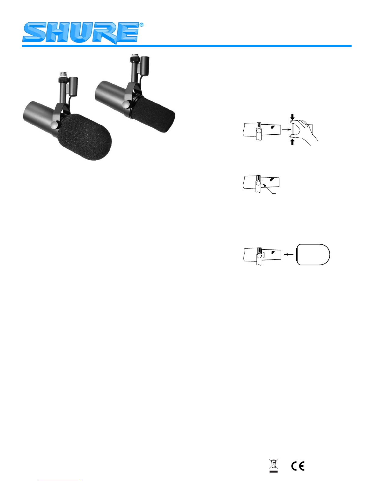
WINDSCREEN
Use the standard windscreen for general voice and instru-
mental applications. Use the supplied A7WS windscreen for
close-talk applications, such as voice overs or radio an-
nouncements, as it offers maximum protection from plosive
breath noise and creates a warmer, more intimate sound.
To install the A7WS, follow these instructions:
1. To avoid tearing the windscreen during removal, grip it
from the plastic ring and the base and remove by gently
pulling and twisting.
2. If desired, adhere the supplied velcro strips around the mi-
crophone grille, approximately one inch from the base of
the grille (as shown above) to hold new windscreen in
place.
3. Install the A7WS windscreen by stretching over the velcro
strips, then squeezing at the base of the windscreen to ad-
here to the velcro. No velcro strip inside the windscreen
is needed, as the windscreen itself adheres to the velcro.
To remove, grip at the base of the windscreen and pull
while twisting.
VELCRO STRIP
MOUNTING INSTRUCTIONS
The SM7B can be mounted on a microphone stand or hung
from a boom. It is shipped in the boom mounting configuration
(see Figure 1). To set up the SM7B in the microphone stand
mounting configuration (see Figure 2), proceed as follows:
1. Remove tightening nuts on the sides (see Figure 7).
2. Remove the fitted washers, the lock washers, the outer
brass washers, and the brass sleeves.
3. Slide the bracket off the microphone. Be careful not to lose
the washers still on the microphone.
4. Invert and rotate the bracket. Slide it back onto the bolts
over the brass and plastic washers still on the microphone.
The bracket should fit so the XLR connector faces the rear
of the microphone, and the Shure logo on the back of the
microphone is right-side up.
5. Replace the brass sleeves. Be sure they are seated proper-
ly within the inner washers.
6. Replace the outer brass washers, the lock washers and the
fitted washers.
7. Replace the tightening nuts and tighten the microphone at
the desired angle.
NOTE: If the tightening nuts do not hold the microphone
in position, one or both of the brass sleeves may not be
properly seated within all the washers.
Model SM7B User Guide
27B3128 (Rev. 2)
©2005, Shure Incorporated Printed in U.S.A.


