Shure 888TT User manual

DTMF AIRCRAFT MICROPHONE
The Shure Model 888TT is handheld, amplified, noise–
cancellingDTMFcommunications microphone that isFAA
Certified for aircraft application (TSO-C58a). In addition to
its extremely clear transmission, even in noisy environ-
ments, the 888TT has very low sensitivity to hum pickup
and low susceptibility to radio frequency interference.
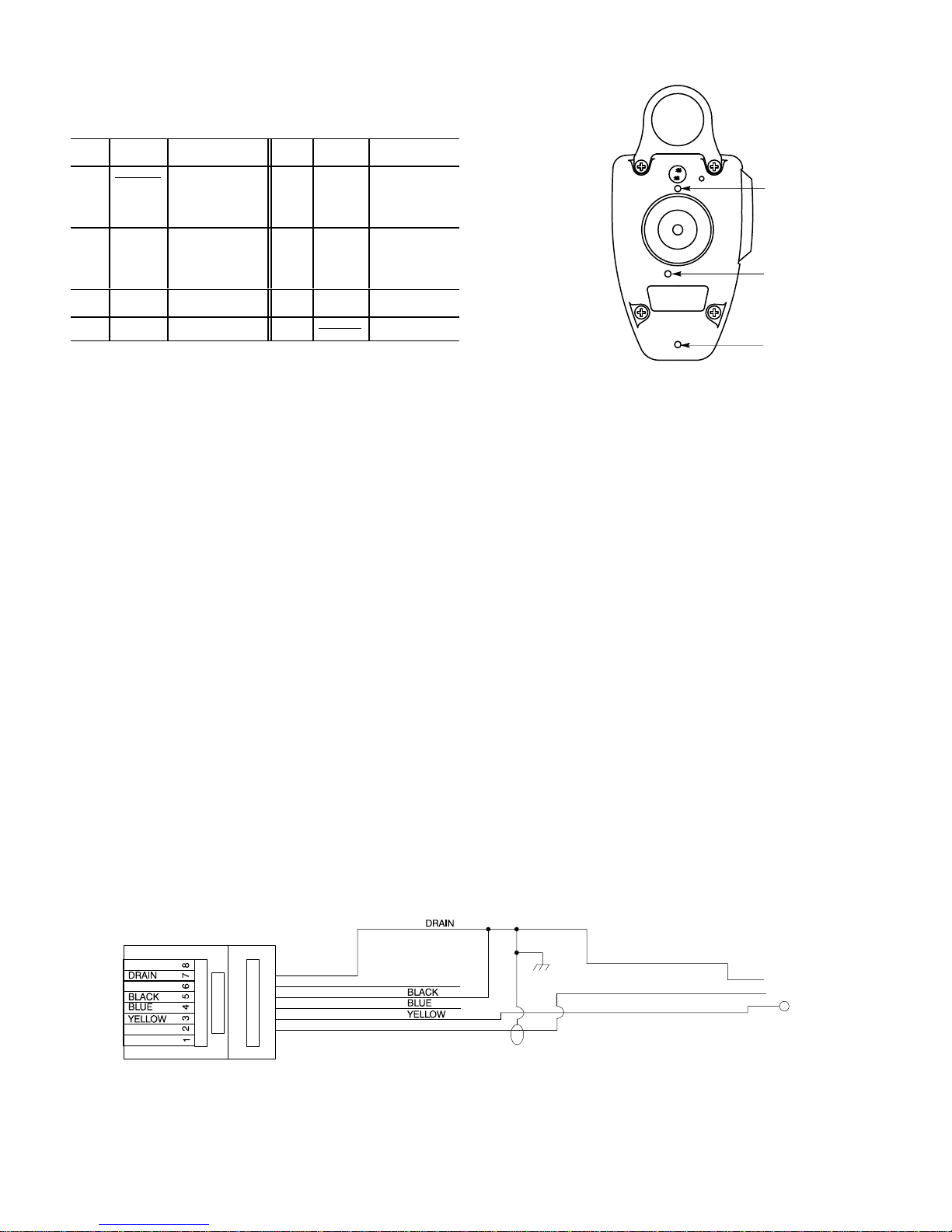
Ininstanceswheretransmitterinputgainrequiresmicro-
phone sensitivity modification, the 888TT has limited ac-
cess external screwdriver controls for independent adjust-
ment of both mic audio and DTMF levels. This eliminates
the problem of fixed audio levels that require disassem-
bling the microphone for adjustments. Restricted control
access,however,preventsaccidentalchangescommonto
other types of external controls.
The microphone has an illuminated keypad made of
tough silicone rubber, with durable printed characters that
willlast the life ofthe microphone. The keypadis backlit by
red LEDs, easily visible during night operation, minimizing
eye readjustment for night vision.
The 888TT is designed for use with most currently avail-
ableaircraft radios.Forinstallation convenience,allmicro-
phone and signaling functions, including keypad illumina-
tion,arepowereddirectlyfromthemicrophoneinputcircuit
of most transmitters, reducing the need for equipment
modification. A three-conductor MODULINKcable (sold
separately)hasatelephone-typemodularplug, with an ef-
fective strain relief, to connect to the microphone and a
PJ-068 plug on the equipment end for connection to most
aircraft radios. This cable can be instantly changed or re-
placed without soldering.
The 888TT is ergonomically designed; it fits naturally
and comfortably in the hand and is not affected by heat or
humidity. The voice-entry port is at the top of the micro-
phone body for simple, natural transmitting. The rugged
ARMO-DURcase is immune to oil, grease, most fumes
and solvents, salt spray, sun, rust and corrosion. The
888TT is outstanding in its ability to withstand mechanical
shocks and vibration. Its Million-Cycle PlusTM leaf-type
switch is a double-pole, single-throw type, designed to re-
sisttheeffectsofsevereoperatingconditionsandconstant
use. It has nickel-silver blades with palladium-alloy con-
tacts for reliable oxidation-free operation.
The microphone is supplied with output levels factory
preset to meet TSO-C58a requirements. Adjustments
should be made only by an FAA Approved Service Facility
or the Shure Service Department.
The 888TT is supplied with a small screwdriver for re-
leasing the modular-plug microphone cable from the case
andforadjustingthemicrophoneamplifier gain and DTMF
level. A mounting loop is supplied affixed to the micro-
phone,andmountingbracketsforattachingtoradioequip-
ment or other surfaces are available in quantities of three
as Shure RK6MB.
Features:
•FAA Certified for aircraft use
•Detachable MODULINK modular-plug coil cord with
PJ-068 aircraft-radio plug
•Noise-canceling with frequency response tailored for
optimum intelligibility
•Top-Talk Sound ChannelTM for clear voice input, easy
handling
•Built-in transistor amplifier powered by carbon-micro-
phone-type circuit
•Illuminated keypad with positive tactile confirmation
and audible verification tones
•Convenient screwdriver-accessible microphone gain
adjustment accommodates most input circuits
•Simple easy-to-use continuous-tone dialing
•Screwdriver accessible DTMF level adjustment, inde-
pendent of microphone gain setting
•Low sensitivity to hum and rf interference
•Rugged Million-Cycle PlusTM leaf-type switch stands
up under severe environments and constant use
•High impact ARMO-DURcase, strong, lightweight,
comfortable to the touch in hot or cold environments
•Rugged and dependable under all operating condi-
tions
Shure Brothers Incorporated
222 Hartrey Avenue
Evanston IL 60202-3696 U.S.A.
Model 888TT User Guide
27A3041 (RL)
E1998, Shure Brothers Incorporated Printed in U.S.A.

2
SPECIFICATIONS
Type
Electret condenser, noise canceling, with transistor pre-
amplifier, DTMF signaling circuitry, illuminated keypad
Frequency Response
200 to 4,000 Hz (see Figure 1)
500 1,000 2,000 5,000 10,000 20,00050 100 20020
0
+10
–10
TYPICAL FREQUENCY RESPONSE
FIGURE 1
Polar Pattern
Bidirectional, noise canceling
Electrical Characteristics
Operating Voltage
8 V 12 V 28 V Notes
Audio Output Level*
(100 µbar acoustic
test signal at 1
kHz, 10 mm)
–11.5 dBV
(266 mV) –11.0 dBV
(281 mV) –10.0 dBV
(316 mV)
Audio trim-
potinfactory
preset posi-
tion
DTMF Output Level –12.8 dBV
(230 mV) –12.0 dBV
(250 mV) –11.2 dBV
(275 mV) DTMF trim-
potinfactory
preset posi-
tion
Dc Supply Current{6 mA 12 mA 36 mA
*Standard electrical test circuit per RTCA DO-170
{Microphone is powered only while PTT switch is depressed (standby
current = 0 if PTT switch is released)
Environmental Conditions
Operating Temperature: –40 to 60°C (–40 to 140°F)
Storage Temperature: –54 to 85°C (–65 to 185°F)
Relative Humidity: 0 to 95% (non-condensing)
Microphone Connector
6-conductor modular telephone type
PTT Switch assembly
Mechanical: Double-pole, single-throw, leaf-type, nor-
mally open
Cable
ALM-88, detachable MODULINK, 0.65 m (2.1 ft) coiled
(1.8 m [6 ft] extended) cord with modular plug on micro-
phone end and PJ-068 aircraft connector on equipment
end
Construction
Case: Black textured high-impact ARMO-DUR
Switch Button: Black ARMO-DUR
Keypad: Molded silicone rubber
Hangup Loop: Matte finish stainless steel
Dimensions
See Figure 2
44.4 mm
40.4 mm
(1-19/32 IN.)
(1-3/4 IN.)
70 mm
64 mm
(2-1/2 IN.)
(2-3/4 IN.)
101 mm
(3-31/32 IN.)
1.9 mm
(5/64 IN.) 42.6 mm
(1–11/16 IN.)
36.9 mm
(15/32 IN.)
25.4 mm
(1 IN.)
OVERALL DIMENSIONS
FIGURE 2
Net Weight (including cable and connector)
283 g (10 oz)
Certification
FAA Certified for aircraft under TSO-C58a requirements
FAA CERTIFICATION
The Model 888TT is FAA Certified for aircraft use under
FAATSO-C58arequirements.TomaintainthisFAACertifi-
cation, any service required for the Model 888TT must be
performed by Shure Brothers Incorporated, or by an FAA
Approved Service Facility.
MOUNTING
The 888TT is equipped with a rear-case hang-up loop
and a hang-up button for use with a mounting bracket on
associated equipment.
Heavy-duty chrome-plated mounting brackets are avail-
able in quantities of three as Shure Part No. RK6MB.
CABLE
Toattachthe cable to the 888TT,insertthe modular tele-
phone-typeplugin themicrophonejackuntilitlocks. Tore-
move the cable from the microphone, insert the small
screwdriver supplied with the 888TT in case hole “A” just
above the cable jack (see Figure 4) to unlock the plug and
withdraw the plug from the jack.

3
Microphoneconnectorwiringisshowninthetablebelow.
Microphone Connector Wiring
Pin Color Function Pin Color Function
1 N.C. 5 Black PTT
Switch
Ground
2 White Dc Bias (+),
Audio Out 6 Red Audio Out
(Ac
coupled)
3 Yellow PTT Switch 7 Drain Ground
4 Blue NC 8 N.C.
The ALM-88 cable is wired at the microphone connector
as shown in Figure 3 at the bottom of the page.
ADJUSTMENTS
Operation of microphone and DTMF functions requires
thatthe888TTbeconnectedtothecommunicationsequip-
ment and that the equipment power is turned on.
After connection to the communications set, turn the
equipmentpowerOn. Powerapplicationcanbeverifiedby
pressingthepush-to-talkswitchandobservingthe keypad
LED backlighting.
Factory preset microphone audio and DTMF levels are
correct for aircraft radios with standard input circuits (as
definedinRTCADO-170),andleveladjustmentshouldnot
ordinarily be necessary. When such adjustment is neces-
sary, it should be performed only by Shure Brothers Inc. or
by an FAA Approved Service Facility. Use the supplied
screwdrivertoadjustthemicrophonesensitivityandDTMF
output levels as follows:
1.
Microphone sensitivity:
Press the push-to-talk but-
ton and speak normally into the microphone while
checking transmitter modulation. Adjust the micro-
phonesensitivitycontrol(caseback,hole“B” in Figure
4) and repeat the talk test as required.
DTMF LEVEL
ADJUST (C)
MICROPHONE
SENSITIVITY
ADJUST (B)
CABLE
RELEASE (A)
MICROPHONE CASE BACK
FIGURE 4
2.
DTMF output:
Pressand holdthepush-to-talkbutton.
Depressand hold down a keypad button foracontinu-
ous tone. Adjust the DTMF output control (case back,
hole “C” in Figure 4) as required.
OPERATION
Voice Transmission
1. Hold the microphone comfortably in the hand posi-
tioned so that the Top-Talk Sound ChannelsTM at the
topofthecasearenearthemouth.Theclearestsound
is often obtained with the microphone at the corner of
the mouth, with the cable away from the face.
2. Depress the push-to-talk button and make sure the
equipment is in the transmit mode before speaking.
Dialing
1. Press and hold the push-to-talk button.
2. Pressthedesiredkeypadbuttonsinsequence.Ahigh-
pitched tone will confirm that the code has been trans-
mitted. (The microphone audio is muted during DTMF
tone transmission.)
REPLACEMENT PARTS
Modular plug-cable with PJ-068 plug assembly ALM-88. .
FURNISHED ACCESSORY
Screwdriver 65A1587. . . . . . . . . . . . . . . . . . . . . . . . . . . . . .
OPTIONAL ACCESSORY
Mounting Bracket (3 in kit) RK6MB. . . . . . . . . . . . . . . . . .
TIP (PTT)
SLEEVE (GROUND)
RING (AUDIO)
PJ-068 CONNECTOR (TO RADIO)
RJ11 CONNECTOR (TO MICROPHONE)
NC
NC
RED
WHITE
WHITE
RED
MODULINK CABLE WIRING
FIGURE 3

4
ENVIRONMENTAL QUALIFICATION FORM, TSO-C58a
DO-170
PARA. # CONDITIONS DO-160C
PARA. # DESCRIPTION OF TESTS
3.1.1 Ground Survival Low Tempera-
ture and Operating Low Tem-
perature
4.5.1 Microphone tested to Category D1
3.1.2 Ground Survival High Temper-
ature and Short-Time Operat-
ing High Temperature
4.5.2 Microphone tested to Category D1
Operating High Temperature 4.5.3 Microphone tested to Category D1
3.1.3 Altitude 4.6.1 Microphone tested at altitude equivalent to
15,200 m (50,000 ft) = 11.6 kPa (116 mbar, 87
mm [3.42 in.] Hg)
3.1.4 Decompression 4.6.2 Microphone tested at altitude equivalent to
15,200 m (50,000 ft)
3.1.5 Overpressure 4.6.3 Microphone tested at pressure = 170 kPa; equiv-
alent altitude = –15,000 ft
2.11 &
3.2 Temperature Variation – Pre-
amplifier 5.3 Microphone tested to Category B for two cycles.
3.3 Humidity 6.3.1 Microphone tested to Category A for 2 cycles.
3.5 Vibration 8.5 Microphone tested to Categories N, B, & M
(Table 8-1, Not on Vibration Isolators)**
3.6 Magnetic Effect 15.3 Microphone tested to Equipment Class Z; no
magnetic properties
3.7 Voltage Spike Conducted 17.3 Microphone tested to Category A
3.8.1 Induced Signal Susceptibility* 19.3 Microphone tested to Category Z
3.9 Radiated rf Susceptibility*[20.5[Microphone tested to Category A
3.10 Emission of rf Energy* 21.4 Microphone tested to Category Z
3.11 Final Distortion After all required environmental tests micro-
phone meets requirements of DO-170, 2.2
3.12 Push-To-Talk Switch Life After all required environmental tests micro-
phone meets requirements of DO-170, Appendix
B, T-7 and 2.9
Fire Retardance In accordance with FAR 25; 25.869(a)(4) and
Appendix F, Part I (a)(3)(b)***
*Tests performed at Radiometrics Midwest Corporation,
Lombard, IL
[Tested to DO-160B
**Tests performed at Elite Electronic Engineering,
Downers Grove, IL
***Tests performed at Gaynes Test Laboratories,
Chicago, IL
All other tests performed at Shure Brothers Inc.,
Evanston, IL
INFORMATION TO USERS
This equipment has been tested and found to comply with the
limits for a Class B digital device pursuant to Part 15 of the FCC
Rules. These limits are designed to provide reasonable protection
againstharmfulinterferenceinaresidentialinstallation.Thisequip-
ment generates, uses, and can radiate radio frequency energy,
and, if not installed and used in accordance with the instructions,
may cause harmful interference to radio communications. Howev-
er,thereisnoguaranteethatinterferencewillnotoccurinaparticu-
lar installation. If this equipment does cause harmful interference
toradioortelevisionreception,which can bedeterminedbyturning
the equipment off and on, the user is encouraged to try to correct
the interference by one or more of the following measures:
Reorient or relocate the receiving antenna.
Increase the separation between the microphone and receiver.
Connectthemicrophonetransmitterintoanoutletonacircuitdif-
ferent from that to which the receiver is connected.
Consult the dealer or an experienced radio/TV technician for
help.
Other manuals for 888TT
1
Other Shure Microphone manuals

Shure
Shure Microflex MX400 Series User manual

Shure
Shure PSM400 Wireless Personal User manual

Shure
Shure PG ALTA PGA181 User manual

Shure
Shure SM94 User manual

Shure
Shure SM58LC User manual

Shure
Shure M73G User manual

Shure
Shure VP88 User manual

Shure
Shure BETA 181 User manual

Shure
Shure PEISL-SP User manual

Shure
Shure Microflex MX200 Series User manual