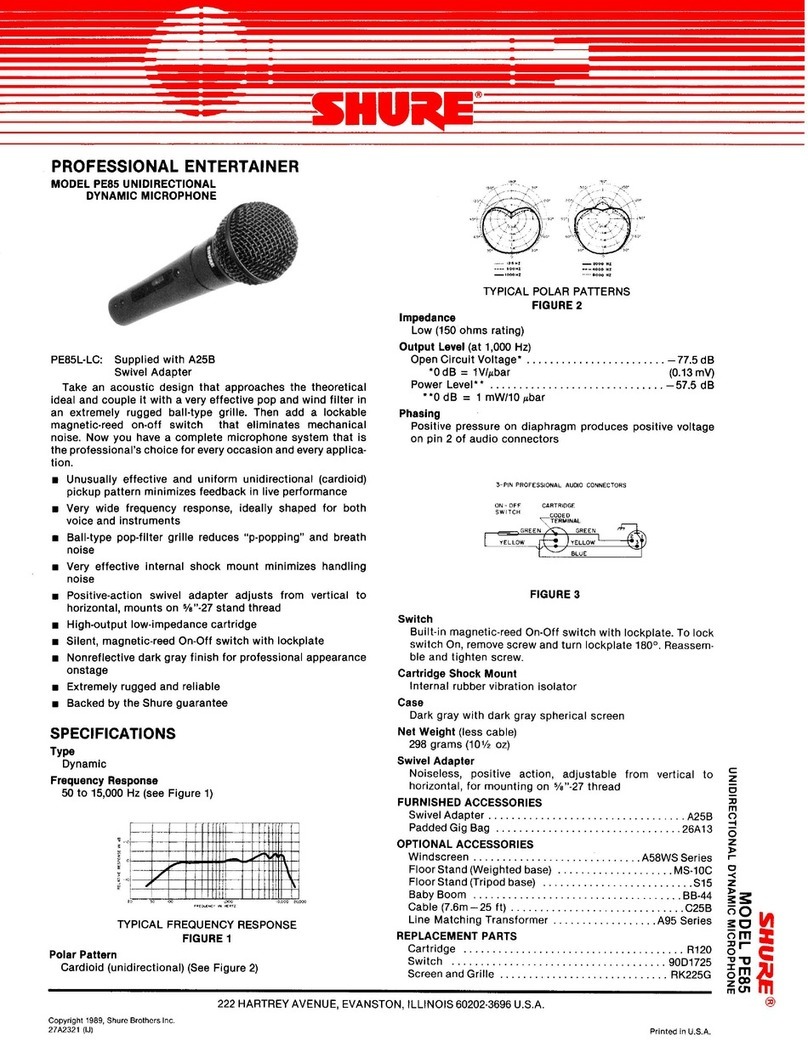
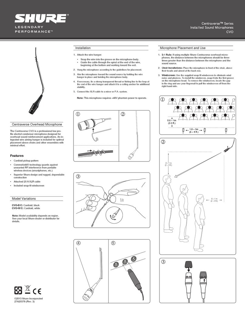
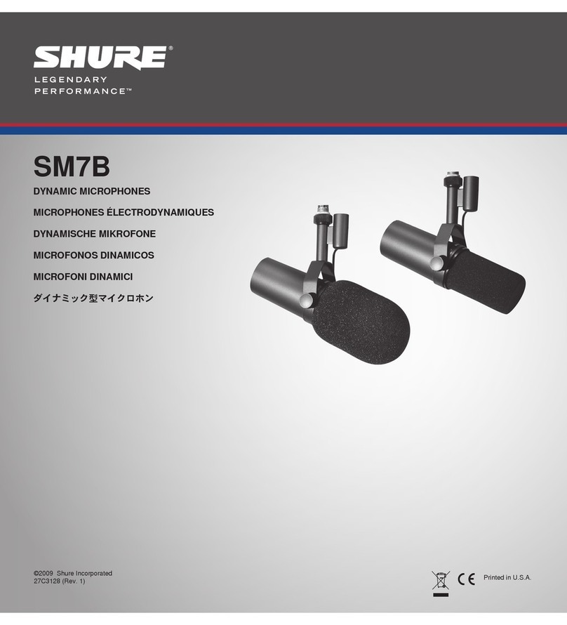
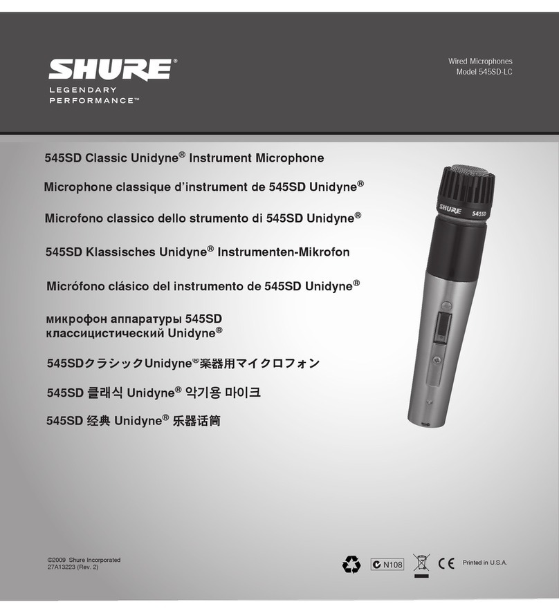
Shure SM7B User manual

prin
©2009 Shure Incorporated
27C3128 (Rev. 1) Printed in U.S.A.
SM7B
MICROPHONES ÉLECTRODYNAMIQUES
DYNAMISCHE MIKROFONE
MICROFONOS DINAMICOS
MICROFONI DINAMICI
ダイナミック型マイクロホン
DYNAMIC MICROPHONES


3
SM7B
DYNAMIC MICROPHONES
The Model SM7B dynamic microphone has a smooth, flat, wide-range frequency
response appropriate for music and speech in all professional audio applications.
It features excellent shielding against electromagnetic hum generated by computer
monitors, neon lights, and other electrical devices. In addition to its standard wind-
screen, it also includes the A7WS windscreen for close-talk applications.
The SM7B is an outstanding choice for the following applications:
• Recording Studio—Instrumental and Vocal
• Location Recording
• Motion Picture and Television Scoring
• Television, Talk Shows, and News Desks
• Radio Announcing and Production
• Narration
FEATURES
• Flat, wide-range frequency response for clean and natural reproduction of both
music and speech
• Switchable bass rolloff and mid-range emphasis (presence boost) settings
• Shielded against broadband interference from computer monitors and other
electrical devices—excellent rejection of electromagnetic hum
• Internal “air suspension” shock isolation virtually eliminates mechanical noise
transmission
• A7WS windscreen included for close-up vocals or narration
• Swiveling bracket with integrated stand adapter for easy mounting and precise
microphone positioning
• Cardioid polar pattern, uniform with frequency and symmetrical about axis, to
provide maximum rejection and minimum coloration of off-axis sound
• Rugged construction and excellent cartridge protection for outstanding reliability
WINDSCREEN
Use the standard windscreen for general voice and instrumental applications. Use
the supplied A7WS windscreen for close-talk applications, such as voice overs or
radio announcements, as it offers maximum protection from plosive breath noise
and creates a warmer, more intimate sound.
To install the A7WS, follow these instructions:
1. To avoid tearing the windscreen during
removal, grip it from the plastic ring and
the base and remove by gently pulling and
twisting.
2. If desired, adhere the supplied velcro strips
around the microphone grille, approximately
one inch from the base of the grille (as
shown) to hold new windscreen in place.
3. Install the A7WS windscreen by stretching
over the velcro strips, then squeezing at
the base of the windscreen to adhere to the
velcro. No velcro strip inside the windscreen
is needed, as the windscreen itself adheres
to the velcro. To remove, grip at the base of
the windscreen and pull while twisting.
SPECIFICATIONS
velcro strip
Type Dynamic (moving coil)
Frequency Response 50 to 20,000 Hz
Polar Pattern Cardioid
Output Impedance EIAratedat150Ω(150Ωactual)
Sensitivity
(at 1 kHz, open circuit
voltage)
−59dBV/Pa(1.12mV)
1 Pascal=94 dB SPL
Hum Pickup
(typical, at 60 Hz, equiva-
lentSPL/mOe)
11 dB
Polarity Positive pressure on diaphragm produces positive
voltage on pin 2 with respect to pin 3
Weight Net: 0.764 kg (1.69 lbs)
Case Dark gray enamel aluminum and steel case with
dark gray foam windscreen.
CERTIFICATION
EligibletobearCEMarking.ConformstoEuropeanEMCDirective2004/108/EC.
Meets Harmonized Standards EN55103-1:1996 and EN55103-2:1996, for residen-
tial (E1) and light industrial (E2) environments.
The Declaration of Conformity can be obtained from:
Authorized European representative:
Shure Europe GmbH
Headquarters Europe, Middle East & Africa
Department EMEA Approval
Wannenacker Str. 28
D-74078 Heilbronn, Germany
Phone: +49 7131 72 14 0
Fax: +49 7131 72 14 14
E-Mail: EMEAsupport@shure.de
TheoutputleveloftheSM7Bis-59dBV/Pa.Fortypicalspeechapplications,three
inches from the grille, the SM7B requires at least +60 dB of gain at the microphone
preamp. Many modern microphone preamps, which are designed for the “hot” out-
put level of condenser microphones, provide only 40 to 50 dB of gain.

4
MOUNTING INSTRUCTIONS
The SM7B can be mounted on a microphone stand or hung from a boom. It is shipped
in the boom mounting configuration. To set up the SM7B in the microphone stand
mounting configuration, proceed as follows:
1. Remove tightening nuts on the sides.
2. Remove the fitted washers, the lock washers, the outer brass washers, and the
brass sleeves.
3. Slide the bracket off the microphone. Be careful not to lose the washers still on the
microphone.
4. Invert and rotate the bracket. Slide it back onto the bolts over the brass and plastic
washers still on the microphone. The bracket should fit so the XLR connector faces
the rear of the microphone, and the Shure logo on the back of the microphone is
right-side up.
5. Replace the brass sleeves. Be sure they are seated properly within the inner
washers.
6. Replace the outer brass washers, the lock washers and the fitted washers.
7. Replace the tightening nuts and tighten the microphone at the desired angle.
NOTE: If the tightening nuts do not hold the microphone in position, one or both of the
brass sleeves may not be properly seated within all the washers.
RIGHT SIDE VIEW REAR VIEW
XLRCONNECTOR
RIGHT SIDE VIEW REAR VIEW
ACCESSORIES AND PARTS
Furnished Accessories
Switch Cover RPM602
Windscreen - Large A7WS
Optional Accessories
Desk Stand S37A
TRIPLE-FLEX™ Cable and Plug 7.6 m (25 ft.) C25F
Replacement Parts
Cartridge RPM106
Windscreen - Small RK345
Nut/Washer RPM604
BOOM MOUNTING CONFIGURATION
MICROPHONE STAND MOUNTING CONFIGURATION
98765432 98765432
+20
+10
0
–10
–20
dB
20 50 100 1000 10000 20000
Hz
SWITCH COVER
Flat Response Bass Rolloff Presence Boost

189.7 mm
(7.469 in.)
95 mm
(3.75 in.)
25.4 mm
(1 in.)
48 mm
(1.890 in.)
117 mm
(4.594 in.)
63.5 mm
(2.500 in.)
96 mm
(3.775 in.)
5
BRASS WASHERS
LOCKWASHER
FITTED WASHER PLASTIC WASHER
MOUNTINGBRACKET
BRASS SLEEVE
TIGHTENING NUT
MOUNTING ASSEMBLY - EXPLODED VIEW
SWITCHCOVER

MICROPHONES ÉLECTRODYNAMIQUES
Le microphone électrodynamique SM7B a une réponse en fréquence uniforme et
plate sur une gamme étendue, convenant à la musique et la parole dans toutes
les applications audio professionnelles. Il est doté d’un excellent blindage contre le
ronflement électromagnétique généré par les moniteurs d’ordinateur, néons et au-
tres appareils électriques. En plus de sa bonnette anti-vent standard, il comprend la
bonnette anti-vent A7WS pour les applications de proximité.
Le SM7B est le choix idéal pour les applications suivantes :
• Studio d’enregistrement—Instruments et voix
• Enregistrement en extérieur
• Sonorisation de film et de télévision
• Télévision, émissions-débat et informations
• Annonces radio et réalisation
• Narration
CARACTÉRISTIQUES
• Réponse en fréquence plate et sur une gamme étendue pour une reproduction
pure et naturelle de la musique et de la parole
• Atténuation des graves et accentuation en milieu de gamme (amplification de
présence) réglables par interrupteur
• Blindé contre les parasites à large bande émis par les moniteurs d’ordinateur et
autres appareils électriques—excellent rejet du ronflement électromagnétique
• Isolement à amortisseur pneumatique interne qui élimine virtuellement la
transmission des bruits mécaniques
• Bonnette anti-vent A7WS incluse pour la narration ou le captage vocal rapproché
• Support articulé à adaptateur de pied intégré pour un montage facile et un
placement précis du microphone
• Courbe de directivité cardioïde uniforme selon la fréquence et symétrique par
rapport à l’axe pour fournir un rejet maximum et une coloration minimum des
sons hors axe
• Construction robuste et excellente protection de la capsule pour une fiabilité à
toute épreuve
BONNETTE ANTI-VENT
Utiliser la bonnette anti-vent standard pour les applications vocales et instrumen-
tales standard. Utiliser la bonnette anti-vent A7WS fournie pour les applications de
proximité, telles que les voix off ou les annonces radio, car elle offre une protec-
tion maximum contre les bruits de respiration et les explosives et crée un son plus
chaud et plus intime.
Pour installer la bonnette A7WS, procéder
comme suit :
1. Pour éviter de déchirer la bonnette anti-vent
quand on l’enlève, la saisir par l’anneau en
plastique et la base et la retirer en tirant
doucement avec un mouvement de torsion.
2. Le cas échéant, coller les bandes Velcro
fournies autour de la grille du microphone,
à environ 25 mm de la base de la grille
(comme illustré ci-dessus) pour maintenir la
bonnette anti-vent neuve en place.
3. Pour installer la bonnette anti-vent A7WS,
l’étirer sur les bandes Velcro puis la serrer
à la base pour qu’elle adhère au Velcro.
Aucune bande Velcro n’est nécessaire à
l’intérieur de la bonnette car celle-ci adhère
au Velcro. Pour l’enlever, saisir la base
de la bonnette anti-vent et la tirer avec un
mouvement de torsion.
Caractéristiques
Bande Velcro
SM7B
Type Dynamique (bobine mobile)
Réponse en fréquence 50 à 20.000 Hz
Courbe de directivité Cardioïde
Impédance de sortie NominaleEIAà150Ω(150Ωréelle)
Sensibilité
(à 1 kHz, tension en
circuit ouvert)
–59dBV/Pa(1,12mV)
1 Pascal=94 dB NPA
Captage du ronflement
(typique, à 60 Hz,
équivalentNPA/mOe)
11 dB
Polarité Une pression acoustique positive sur le diaphragme
produit une tension positive sur la broche 2 par rap-
port à la broche 3.
Poids Net: 0,764 kg
Corps Corps en acier et en aluminium vernis gris foncé
avec bonnette anti-vent en mousse gris foncé.
6
HOMOLOGATION
Autorisé à porter la marque CE. Conforme à la directive européenne CEM
2004/108/CE.ConformeauxnormesharmoniséesEN55103-1:1996etEN55103-
2:1996 pour les environnements résidentiels (E1) et d’industrie légère (E2).
La déclaration de conformité peut être obtenue de l’adresse suivante:
Représentant agréé européen :
Shure Europe GmbH
SiègeEurope,Moyen-OrientetAfrique
Homologation EMEA
Wannenacker Str. 28
D-74078 Heilbronn, Germany
Phone: +49 7131 72 14 0
Fax: +49 7131 72 14 14
Email: [email protected]
LeniveaudesortieduSM7Best-59dBV/Pa.Pourlesapplicationsd’ordrevocal
typiques, à savoir trois pouces de la grille, le SM7B exige un gain d’au moins +60
dB au niveau du préamplificateur du microphone. De nombreux préamplificateurs
de microphones modernes, conçus pour le niveau de sortie “plus haut” des micro-
phones électrostatiques, ne fournissent que 40 à 50 dB de gain.

PLAQUE DE PROTECTION DE SÉLECTEUR
INSTRUCTIONS D’INSTALLATION
Le SM7B peut être monté sur un pied de microphone ou pendu à un flexible. Il est
expédié dans la configuration de montage sur flexible. Pour mettre le SM7B en con-
figuration de montage sur pied, procéder comme suit :
1. Enlever les écrous de serrage des côtés.
2. Retirer les rondelles ajustées, les rondelles-frein, les rondelles en laiton exté-
rieures et les manchons en laiton.
3. Sortir le support du microphone en le faisant glisser. Faire attention à ne pas per-
dre les rondelles restant sur le microphone.
4. Retourner et tourner le support. Le remettre sur les boulons par-dessus les
rondelles en laiton et en plastique encore sur le microphone. Le support doit
s’ajuster de manière à ce que le connecteur type XLR soit orienté vers l’arrière
du microphone et que le logo Shure situé au dos du microphone soit à l’endroit.
5. Remettre les manchons en laiton en place. Veiller à ce qu’ils soient correctement
logés à l’intérieur des rondelles intérieures.
6. Remettre en place les rondelles en laiton extérieures, les rondelles-frein et les
rondelles ajustées.
7. Remettre les écrous de serrage et serrer le microphone à l’angle souhaité.
REMARQUE : Si le serrage des écrous ne maintient pas le microphone en place,
il est possible qu’un ou les deux manchons en laiton ne soient pas correctement
logés à l’intérieur des rondelles.
VUELATÉRALEDROITE VUE ARRIÈRE
CONNECTEURTYPEXLR
VUELATÉRALEDROITE VUE ARRIÈRE
ACCESSOIRES ET PIÈCES
Accessoires fournis
Plaque de protection de sélecteur RPM602
Bonnette anti-vent, grande A7WS
Accessoires en option
Socle de pupitre à conception extra-plate S37A
Câble et fiche TRIPLE-FLEX™, 7.6 m (25 pi) C25F
Pièces de rechange
Capsule RPM106
Bonnette anti-vent, petite RK345
Écrou/rondelle RPM604
CONFIGURATION DE MONTAGE SUR FLEXIBLE
CONFIGURATION DE MONTAGE SUR PIED
250 Hz
500 Hz
1000 Hz
2500 Hz
8300 Hz
98765432 98765432
+20
+10
0
–10
–20
dB
20 50 100 1000 10000 20000
Hz
7
Réponse plane Atténuation des graves Amplification de présence

PLAQUEDEPROTECTIONDESÉLECTEUR
RONDELLESEN
LAITON
RONDELLE-FREIN
RONDELLE
AJUSTÉE RONDELLEENPLASTIQUE
BLOCDEMONTAGE
MANCHONENLAITON
ÉCROUDESERRAGE
MONTURE - VUE ÉCLATÉE
189.7 mm
(7.469 in.)
95 mm
(3.75 in.)
25.4 mm
(1 in.)
48 mm
(1.890 in.)
117 mm
(4.594 in.)
63.5 mm
(2.500 in.)
96 mm
(3.775 in.)
8

DYNAMISCHE MIKROFONE
Das Modell SM7B ist ein dynamisches Mikrofon mit einem ausgeglichenen, linearen
Frequenzgang und einem großen Übertragungsbereich, das sich für Musik- und
Sprachabnahme bei allen Profi-Audioanwendungen eignet. Es weist eine her-
vorragende Abschirmung gegenüber elektromagnetischen Einstrahlungen wie
beispielsweise von Computermonitoren, Neonleuchten oder anderen elektrischne
Geräten, auf. Neben dem standardmäßigen Windschutz ist auch der Windschutz
A7WS für Nahbesprechungsanwendungen im Lieferumfang enthalten.
Das SM7B stellt für folgende Anwendungen eine hervorragende Wahl dar:
• Aufnahmestudio - Instrumental-, Gesangs- und Sprachaufnahmen
• Elektronische Berichterstattung
• Film- und Fernsehmusikaufnahmen
• Fernsehen, Talk-Shows und Nachrichtensprecher
• Radiosprecher und -produktion
• Sprachaufnahmen
TECHNISCHE EIGENSCHAFTEN
• Linearer Frequenzgang mit großem Übertragungsbereich für reine und natürliche
Wiedergabe von Musik und Sprache
• Umschaltbare Einstellungen für Bassdämpfung und Mittenanhebung
(Präsenzverstärkung)
• Abschirmung gegen Breitbandstörungen durch Computermonitore und andere
elektrische Geräte - hervorragende Unterdrückung von elektromagnetischen
Störungen
• Interne “luftgefederte” Schwingungsdämpfung beseitigt praktisch jegliche
mechanische Geräuschübertragung
• Windschutz A7WS für Nahabnahme von Sängern oder Sprechern
• Schwenkhalterung mit integriertem Stativadapter zur einfachen Montage und
präzisen Mikrofonplatzierung
• Nierencharakteristik mit gleichförmigem Frequenzgang und Achsensymmetrie
bietet maximale Unterdrückung und minimale Verfärbung außeraxialer Klänge
• Robuste Ausführung und ausgezeichneter Kapselschutz für hervorragende
Zuverlässigkeit
WINDSCHUTZ
Der standardmäßige Windschutz sollte für allgemeine Stimm- und
Instrumentalanwendungen verwendet werden. Der mitgelieferte Windschutz A7WS
bietet einen maximalen Schutz vor Popp-Geräuschen und eignet sich am besten für
Nahabnahmeanwendungen, wie z. B. Sprachaufnahmen oder Radiosprecher was zu
einen wärmeren, sympathischeren Klang führt.
Zur Anbringung des A7WS folgende Schritte ausführen:
1. Um zu vermeiden, dass der Windschutz
beim Abnehmen reißt, am Kunststoffring
und Sockel anfassen und durch behut-
sames Ziehen und Drehen abnehmen.
2. Falls gewünscht, die mitgelieferten Velcro-
Streifen um den Mikrofonkorb herum
ankleben, ungefähr 2-3 cm vom Korbsockel
entfernt (siehe Abbildung), um den neuen
Windschutz zu fixieren.
3. Den Windschutz A7WS anbringen, indem
er über die Velcro-Streifen gespannt wird
und dann der Windschutz zusammenge-
drückt wird, damit er an den Velcro-Streifen
haftet. Innerhalb des Windschutzes ist
kein Velcro nötig, da er selbst am Velcro
haftet. Zum Abnehmen den Sockel des
Windschutzes festhalten und mit drehenden
Bewegungen abziehen.
TECHNISCHE DATEN
Velcro-Streifen
SM7B
Typ Dynamisch (Tauchspule)
Übertragungsbereich 50 bis 20.000 Hz
Richtcharakteristik Niere
Ausgangsimpedanz EIA-Zulassungbei150Ω(150ΩIstwert)
Empfindlichkeit
(bei 1 kHz, Leerlaufspannung)
–59dBV/Pa
1 Pascal=94 dB Schalldruckpegel
Brummeinkopplung
(typisch, bei 60 Hz, äquivalenter
Schalldruckpegel/mOe)
11 dB
Polarität Positiver Druck an der Membran erzeugt pos-
itive Spannung an Pin 2 in Bezug auf Pin 3.
Gewicht Netto: 0,764 kg
Gehäuse Dunkelgraues Email-Aluminium- und
Stahlgehäuse mit dunkelgrauem
Schaumstoff-Windschutz.
ZERTIFIZIERUNG
Zur CE-Kennzeichnung berechtigt. Entspricht der europäischen Richtlinie zur elek-
tromagnetischenVerträglichkeit2004/108/EG.EntsprichtdenAnforderungender
harmonisierten Normen EN55103-1:1996 und EN55103-2:1996 für Wohngebiete
(E1) und Leichtindustriegebiete (E2).
Die Konformitätserklärung ist über die unten stehende Adresse erhältlich:
9
Bevollmächtigter Vertreter in Europa:
Shure Europe GmbH
Headquarters Europe, Middle East &
Africa
Abteilung: EMEA-Zulassung
Wannenacker Str. 28
D-74078 Heilbronn, Germany
Tel: +49 7131 72 14 0
Fax: +49 7131 72 14 14
Sprachanwendungen mit 7-8 cm Abstand zum Grill erfordert das SM7B
mindestens +60 dB Verstärkung am Mikrofonvorverstärker. Viele mod-
erne Mikrofonvorverstärker, die für den “heißen” Ausgangspegel von
Kondensatormikrofonen konzipiert sind, bieten nur 40 bis 50 dB Verstärkung.
MONTAGEANWEISUNGEN
Das SM7B kann an einem Mikrofonstativ befestigt oder von einem Galgen abge-
hängt werden. Es wird in der Galgenmontage versandt. Zur Einrichtung des SM7B
für die Konfiguration zur Mikrofonstativmontage folgendermaßen vorgehen:
1. Die Klemmmuttern auf den Seiten abnehmen.
2. Die Passscheiben, die Sicherungsscheiben, die äußeren Messingscheiben und
die Messinghülsen entfernen.
3. Die Halterung vom Mikrofon abziehen. Darauf achten, dass die Scheiben, die
sich noch am Mikrofon befinden, nicht verloren gehen.
4. Die Halterung umkehren und drehen. Auf die Schrauben über den Messing-
und Kunststoffscheiben, die sich noch am Mikrofon befinden, zurückschie-
ben. Die Halterung sollte so angebracht werden, dass der XLR-Stecker zur
Mikrofonrückseite weist und das Shure-Logo auf der Mikrofonrückseite nicht auf
dem Kopf steht.
5. Die Messinghülsen wieder anbringen, so dass sie sich richtig innerhalb der in-
neren Scheiben befinden.
6. Die äußeren Messingscheiben, die Sicherungsscheiben und die Passscheiben
wieder anbringen.
7. Die Klemmmuttern wieder anschrauben und das Mikrofon im gewünschten
Winkel befestigen.
HINWEIS: Wenn die Klemmmuttern das Mikrofon nicht sicher halten, sitzen eventu-
ell eine oder beide der Messinghülsen nicht richtig innerhalb von allen Scheiben.
ANSICHTVONRECHTS RÜCKANSICHT
XLR-STECKER
ANSICHTVONRECHTS RÜCKANSICHT
ZUBEHÖRTEILE
Mitgeliefertes Zubehör
Schalterabdeckplatte RPM602
Windschutz, groß A7WS
Sonderzubehör
Tischstativ, flaches Design S37A
TRIPLE-FLEX™-Kabel und Stecker, 7,6 m C25F
Ersatzteile
Kapsel RPM106
Windschutz, klein RK345
Mutter/Unterlegscheibe RPM604
KONFIGURATION ZUR GALGENMONTAGE
KONFIGURATION ZUR MONTAGE AUF MIKROFONSTATIV
250 Hz
500 Hz
1000 Hz
2500 Hz
8300 Hz
10
98765432 98765432
+20
+10
0
–10
–20
dB
20 50 100 1000 10000 20000
Hz
Linearer Frequenzgang Bassdämpfung Präsenzverstärkung
SCHALTERABDECKPLATTE

MESSINGSCHEIBEN
SICHERUNGSSCHEIBE
PASSSCHEIBE KUNSTSTOFFSCHEIBE
MONTAGEKLAMMER
MESSINGHÜLSE
KLEMMMUTTER
BEFESTIGUNGSBAUGRUPPE - EXPLOSIONSDARSTELLUNG
189.7 mm
(7.469 in.)
95 mm
(3.75 in.)
25.4 mm
(1 in.)
48 mm
(1.890 in.)
117 mm
(4.594 in.)
63.5 mm
(2.500 in.)
96 mm
(3.775 in.)
11
SCHALTERABDECKPLATTE

MICROFONOS DINAMICOS
El micrófono dinámico modelo SM7B tiene una respuesta de frecuencia uniforme,
plana y amplia que es adecuada para la reproducción de música y voz en todas las
situaciones de presentaciones profesionales. Cuenta con un blindaje excelente con-
tra el zumbido electromagnético generado por pantallas de computadora, luces de
neón y otros dispositivos eléctricos. Además de su paravientos estándar, incluye el
paravientos A7WS para las situaciones de captación de voz a distancias cortas.
El SM7B es una alternativa excelente para las situaciones siguientes:
• Estudios de grabación—Música instrumental y cantada
• Grabación en sitio
• Grabación de pistas para películas y programas de televisión
• Teledifusión, entrevistas y noticieros por televisión
• Locución y producción de radio
• Narraciones
CARACTERISTICAS
• Una respuesta de frecuencia plana y amplia para brindar una reproducción nítida
y natural de tanto música como voz
• Interruptores de atenuación progresiva de frecuencias bajas y de amplificación
de banda media (aumento de presencia)
• Blindaje contra interferencias de banda ancha generadas por pantallas de
computadoras y otros dispositivos eléctricos — nivel excelente de rechazo de
zumbidos electromagnéticos
• El soporte amortiguado interno con “suspensión neumática” prácticamente
elimina la transmisión de ruidos de origen mecánico.
• Incluye el paravientos A7WS para captar voces a distancias muy cortas
• La escuadra giratoria con adaptador incorporado para pedestal facilita el montaje
del micrófono y permite ajustar su posición de forma precisa
• Su patrón polar de captación de cardioide, uniforme respecto a la frecuencia
y simétrico respecto a su eje, proporciona el rechazo máximo y la coloración
mínima de los sonidos originados fuera de su eje principal de captación
• Fabricación resistente y excelente protección de la cápsula para brindar una
confiabilidad sobresaliente.
PARAVIENTOS
Utilice el paravientos normal para las situaciones generales de captación de voz e in-
strumentos. Utilice el paravientos A7WS incluido para situaciones de captación de voz
a distancias cortas, tales como las grabaciones en estudio y locución radial, puesto
que ofrece la protección máxima contra los ruidos del aliento y crea un sonido más
cálido e íntimo.
Para instalar el A7WS, utilice las instrucciones siguientes:
1. Para evitar romper el paravientos al quita-
rlo, sujételo por el anillo de plástico y por
su base y quítelo tirando y torciéndolo
suavemente.
2. Si así se desea, coloque las tiras de Velcro
provistas alrededor de la malla del micró-
fono, a aproximadamente una pulgada de
la base de la malla (como se ilustra arriba)
para sujetar el paravientos nuevo en su
lugar.
3. Instale el paravientos A7WS estirándolo
sobre las tiras de Velcro y luego comprim-
iendo su base para adherirla al Velcro. No
se necesita una tira de Velcro dentro del
paravientos, puesto que éste se adhiere
por sí solo al material Velcro. Para quitarlo,
sujete la base del paravientos y tire de la
misma mientras se la retuerce.
ESPECIFICACIONES
Tira de Velcro
SM7B
Tipo Dinámico (bobina móvil)
Respuesta de frecuencia 50 a 20.000 Hz
Patrón polar Cardioide
Impedancia de salida clasificadoporEIAa150Ω(150Ωreal)
Sensibilidad
(a 1 kHz, voltaje en circuito abierto)
–59dBV/Pa(1,12mV)
1 Pascal=94 dB SPL
Captación de zumbidos
(típicaa60Hz,SPL/mOeequiva-
lente )
11 dB
Polaridad Una presión positiva en el diafragma del
micrófono produce un voltaje positivo en
la clavija 2 con respecto a la clavija 3
Peso Neto: 0,764 kg (1,69 lb)
Estuche Caja de aluminio y acero con acabado
gris oscuro y paravientos de espuma gris
oscuro.
12
CERTIFICACIONES
Califica para llevar la marca CE. Cumple con la directiva europea de EMC
2004/108/EC.SatisfacelasnormasarmonizadasEN55103-1:1996yEN55103-
2:1996 para entornos de uso residencial (E1) e industrial ligero (E2).
La declaración de conformidad se puede obtener de la siguiente dirección:
Representante autorizado en Europa:
Shure Europe GmbH
Casa matriz para Europa, Medio
OrienteyAfrica
Aprobación para región de EMEA
Wannenacker Str. 28
D-74078 Heilbronn, Germany
Phone: +49 7131 72 14 0
Fax: +49 7131 72 14 14
Email: [email protected] LaintensidaddelaseñaldesalidadelSM7Besde-59dBV/Pa.Parausostípicos
de captación de voz hablada, a tres pulgadas de su rejilla, el SM7B requiere una
ganancia mínima de +60 dB en el preamplificador del micrófono. Muchos pream-
plificadores de micrófonos modernos, que han sido diseñados para las señales de
salida fuertes que producen los micrófonos de condensador, proporcionan única-
mente de 40 a 50 dB de ganancia.

CUBIERTA DE INTERRUPTORES
INSTRUCCIONES DE MONTAJE
El SM7B puede montarse en un pedestal de micrófonos estándar, o en un pedestal
de extensión. Se despacha en configuración de montaje en brazo de extensión. Para
configurar el SM7B para montaje en pedestal de micrófonos, efectúe el procedimiento
siguiente:
1. Retire las tuercas de fijación de los costados.
2. Quite las arandelas moldeadas, las arandelas de seguridad, las arandelas exteri-
ores de latón y los manguitos de latón.
3. Deslice la escuadra para quitarla del micrófono. Evite perder las arandelas que to-
davía están en el micrófono.
4. Invierta y gire la escuadra. Deslícela nuevamente sobre los pernos, sobre las aran-
delas de latón y de plástico que permanecieron con el micrófono. La escuadra debe
quedar orientada de modo que el conector XLR quede hacia la parte trasera del
micrófono y el logotipo Shure de la parte posterior del micrófono esté en posición
derecha.
5. Vuelva a colocar los manguitos de latón. Asegúrese que queden debidamente
asentados en las arandelas interiores.
6. Vuelva a colocar las arandelas exteriores de latón, las arandelas de seguridad y las
arandelas moldeadas.
7. Vuelva a colocar las tuercas de fijación y apriete el micrófono al ángulo deseado.
NOTA: Si las tuercas de fijación no sujetan al micrófono en posición, uno o los dos
manguitos de latón podrían no estar debidamente asentados en las arandelas.
VISTA DERECHA VISTAPOSTERIOR
CONECTORXLR
VISTA DERECHA VISTAPOSTERIOR
ACCESORIOS Y PIEZAS
Accesorios suministrados
Cubierta de interruptores RPM602
Paravientos grande A7WS
Accesorios opcionales
Pedestal para escritorio de bajo perfil S37A
Cable y enchufe TRIPLE-FLEX™, 7,6 m (25 pies) C25F
Repuestos
Cápsula RPM106
Paravientos pequeño RK345
Tuerca/arandela RPM604
CONFIGURACION PARA MONTAJE EN BRAZO
CONFIGURACION PARA MONTAJE EN PEDESTAL DE MICROFONO
13
98765432 98765432
+20
+10
0
–10
–20
dB
20 50 100 1000 10000 20000
Hz
Respuesta plana Atenuación de bajos Aumento de presencia

189.7 mm
(7.469 in.)
95 mm
(3.75 in.)
25.4 mm
(1 in.)
48 mm
(1.890 in.)
117 mm
(4.594 in.)
63.5 mm
(2.500 in.)
96 mm
(3.775 in.)
14
ARANDELASDELATON
ARANDELA DE
SEGURIDAD
ARANDELA
MOLDEADA ARANDELA DE
PLASTICO
ESCUADRADEMONTAJE
MANGUITODELATON
TUERCA DE APRIETE
CONJUNTO DE MONTAJE - DESPIECE
CUBIERTADEINTERRUPTORES

MICROFONI DINAMICI
Il microfono dinamico SM7B presenta una risposta in frequenza ad ampia banda,
piatta e regolare, adatta a tutte le applicazioni audio professionali, sia per riprese
vocali che di brani musicali. È dotato di un’ottima schermatura contro il ronzio
elettromagnetico generato dai monitor, dalle lampade al neon e da altri apparecchi
elettrici.Oltreall’antiventostandard,ladotazionecomprendel’antiventoA7WS,utile
quando si deve tenere il microfono vicino alla bocca.
Il microfono SM7B è una scelta quasi obbligata per le applicazioni seguenti.
• Registrazione in studio, sia per strumenti sia per voci.
• Registrazioni esterne.
• Colonne sonore per spettacoli televisivi e film.
• Notiziari e talk show televisivi.
• Produzione e annunci radiofonici.
• Narrazione.
CARATTERISTICHE
• Risposta in frequenza ad ampia banda, piatta, per riprodurre con straordinaria
naturalezza e chiarezza la voce di oratori e musicisti.
• Impostazioni commutabili per l’attenuazione alle basse frequenze e per l’enfasi
alle frequenze intermedie (amplificazione di presenza).
• Schermatura contro l’interferenza a larga banda causata dai monitor e da altri
apparecchi elettrici, con un’eccellente reiezione del ronzio elettromagnetico.
• Il sistema di “smorzamento pneumatico” interno elimina praticamente la
trasmissione del rumore meccanico.
• La dotazione comprende l’antivento A7WS, adatto a cantanti e oratori che
devono usare il microfono tenendolo vicino alla bocca.
• Staffa girevole, con adattatore per sostegno integrato, per fissare facilmente il
microfono e collocarlo con precisione.
• Diagramma polare a cardioide, uniforme in frequenza e simmetrico rispetto
all’asse, per ottenere la massima reiezione e la minima colorazione dei suoni
fuori asse.
• La costruzione robusta e la protezione della capsula si traducono in un’affidabilità
straordinaria.
ANTIVENTO
L’antivento standard è adatto ad applicazioni generali strumentali e vocali, mentre il
modello A7WS in dotazione va adoperato quando il microfono deve essere tenuto
vicino alla bocca (per esempio in caso di commenti sonori o annunci radiofonici) in
quanto offre la massima protezione dai suoni “esplosivi” della respirazione e crea un
suono più caldo e raccolto.
Installazione dell’A7WS
1. Per evitare di lacerare l’antivento quando lo
togliete, afferratelo per l’anello di plastica e
per la base e staccatelo tirandolo e giran-
dolo delicatamente.
2. Volendo, potete fissare il nuovo antivento
avvolgendo le strisce di Velcro, in dot-
azione, intorno alla griglia del microfono,
a circa 2,5 centimetri dalla base della
griglia stessa (come illustrato nella figura
precedente).
3. Fissate l’antivento distendendolo sopra
le strisce di Velcro ed esercitando pres-
sione sulla sua base per farlo aderire alle
strisce. Non occorre usare nessuna striscia
all’interno dell’antivento, in quanto esso
aderisce al Velcro. Per togliere l’antivento,
afferratelo per la base e staccatelo tirandolo
e girandolo delicatamente.
SPECIFICHE TECNICHE
striscia di velcro
SM7B
Tipo Dinamico (a bobina mobile)
Risposta in frequenza 50 a 20.000 Hz
Diagramma polare Cardioide
Impedenza di uscita ValorenominaleEIA150Ω(150Ωeffettivo)
Sensibilità
(a 1 kHz, tensione a circuito
aperto)
–59dBV/Pa(1,12mV)
1 Pascal=94 dB di SPL
Ricezione del ronzio
(valoretipico,a60Hz,SPL/mOe
equivalente)
11 dB
Polarità Una pressione positiva sul diaframma produce
una tensione positiva sul piedino 2 rispetto al
piedino 3.
Peso Netto: 0,764 kg (1,69 lbs)
Involucro In acciaio e alluminio smaltato, grigio scuro,
con antivento in materiale poliuretanico grigio
scuro.
15
OMOLOGAZIONI
Contrassegnabile con il marchio CE. Conforme alla direttiva europea sulla compati-
bilitàelettromagnetica2004/108/CE.ConformeallenormearmonizzateEN55103-
1:1996 ed EN55103-2:1996 per l’uso in ambienti domestici (E1) e indus¬triali leg-
geri (E2).
La dichiarazione di conformità può essere ottenuta da:
Rappresentante europeo autorizzato:
Shure Europe GmbH
SedeperEuropa,MedioOrientee
Africa
Approvazione EMEA
Wannenacker Str. 28
D-74078 Heilbronn, Germany
Phone: +49 7131 72 14 0
Fax: +49 7131 72 14 14
Email: [email protected] IllivellodiuscitadelmicrofonoSM7Bè-59dBV/Pa.Perapplicazionivocalitipiche,
a tre pollici dalla griglia, il microfono SM7B richiede un guadagno di almeno +60 dB
in corrispondenza del relativo preamplificatore. Molti preamplificatori del microfono
moderni, studiati per un livello di uscita alto dei microfoni a condensatore, fornis-
cono un guadagno di soli 40-50 dB.

PIASTRA DI COPERTURA SELETTORE
ISTRUZIONI PER IL FISSAGGIO
Il microfono SM7B può essere collocato su un sostegno apposito oppure può essere
appeso a un braccio. Viene spedito nella configurazione di fissaggio al braccio. Per
predisporlo in modo da fissarlo a un sostegno, procedete come descritto di seguito.
1. Togliete i dadi di serraggio sui lati.
2. Togliete le rondelle adattate, le rondelle elastiche, le rondelle di ottone esterne e i
manicotti di ottone.
3. Sfilate la staffa dal microfono, facendo attenzione a non perdere le rondelle ancora
inserite.
4. Capovolgete la staffa e giratela, poi inseritela sulle viti sopra le rondelle di ottone e
di plastica rimaste sul microfono. La staffa deve adattarsi in modo che il connettore
XLR sia rivolto verso la parte posteriore del microfono e che il logotipo Shure sulla
parte posteriore sia diritto.
5. Riposizionate i manicotti di ottone, verificando che siano collocati correttamente
nella sede dentro le rondelle interne.
6. Riposizionate le rondelle di ottone esterne, le rondelle elastiche e le rondelle
adattate.
7. Riposizionate i dadi di serraggio e fissate il microfono all’inclinazione desiderata.
NOTA: se i dadi di serraggio non mantengono il microfono bloccato, è possibile che
uno dei manicotti di ottone, o entrambi, non siano inseriti correttamente dentro tutte le
rondelle.
VISTADALLATODESTRO VISTAPOSTERIORE
CONNETTOREXLR
VISTADALLATODESTRO VISTAPOSTERIORE
ACCESSORI E PARTI DI RICAMBIO
Accessori in dotazione
Piastra di copertura selettore RPM602
Antivento, grande A7WS
Accessori opzionali
Sostegno da tavolo a profilo compatto S37A
Cavo e spina TRIPLE-FLEX™ da 7.6 m (25 piedi) C25F
Parti di ricambio
Cartuccia RPM106
Antivento, piccolo RK345
Dado/rondella RPM604
CONFIGURAZIONE MONTAGGIO BRACCIO
CONFIGURAZIONE MONTAGGIO SUPPORTO MICROFONO
16
98765432 98765432
+20
+10
0
–10
–20
dB
20 50 100 1000 10000 20000
Hz
Risposta piatta Attenuazione alle basse frequenze Amplificazione di presenza

189.7 mm
(7.469 in.)
95 mm
(3.75 in.)
25.4 mm
(1 in.)
48 mm
(1.890 in.)
117 mm
(4.594 in.)
63.5 mm
(2.500 in.)
96 mm
(3.775 in.)
17
PIASTRADICOPERTURASELETTORE
RONDELLEDI
OTTONE
RONDELLE
ELASTICHE
RONDELLE
ADATTATE RONDELLADIPLASTICA
STAFFADIMONTAGGIO
MANICOTTODI
OTTONE
DADODISERRAGGIO
COMPONENTI DI MONTAGGIO - ESPLOSO

ダイナミック型マイクロホン
モデルSM7Bダイナミック型マイクロホンのスムーズな広域周波数特性は、プロの
音響用の音楽やスピーチに最適です。PCモニタやネオン管などの電気機器によっ
て発生するハムノイズに対する優れた遮断特性を有しています。標準のウィンドス
クリーンに加えて、近接用のA7WSウィンドスクリーンも付属しています。
SM7Bは次の用途に最適です:
• 録音スタジオ—楽器とボーカル
• ロケ録音
• 映画やテレビの管弦楽ステージ
• テレビ、トーク番組、ニュース番組
• ラジオのアナウンス・制作
• ナレーション
機能
• フラットで広範囲な周波数レスポンスにより、音楽やスピーチをクリーンでナ
チュラルに再生
• 切替え可能な低域ロールオフと中域を強調した(プレゼンスブースト)設定
• PCモニタなどの電気機器からの広帯域干渉を遮断し、ハムノイズを効果的にカ
ット
• 内蔵の「エアサスペンション」ショックアイソレーションにより、メカニカルノ
イズの伝達を低減
• クローズアップのボーカルやナレーション用のA7WSウィンドスクリーン同梱
• スタンドアダプタ一体型のスイベルブラケットにより、取付けやマイクロホン
の位置決めが簡単
• 周波数に対して均一で軸に対称なカーディオイド指向特性により、収音軸を外れ
た音を最大にカットして音質劣化を防止
• 頑丈なボディと優れたカートリッジ保護により卓越した信頼性
ウィンドスクリーン
一般のボイスや楽器用には標準ウィンドスクリーンを使用します。同梱のA7WSウ
ィンドスクリーンはボイスオーバーやラジオ放送のような近接用に使用します。こ
れは、ブレスノイズなどの破裂音を最大限に防ぎ、暖かく親近感のある音を再現す
るからです。
A7WSを取り付けるには、次の手順に従ってく
ださい。
1. ウィンドスクリーンを取り外す際に壊さない
よう、プラスチック製リングとベースをつ
かんでゆっくりとねじりながら引っ張って
外します。
2. 必要に応じて、マイクロホンのグリルのベー
スから約1インチの位置で(上に示すよう
に)、グリルの周りに同梱の面ファスナー
を張り付け、新しいウィンドスクリーンを固
定します。
3. A7WSウィンドスクリーンを面ファスナー上
で延ばし、ウィンドスクリーンのベースを面
ファスナーに押して貼り付けます。ウィンド
スクリーン自体が面ファスナーに接着するの
で、ウィンドスクリーンの内側には面ファス
ナーはいりません。取り外すには、ウィンド
スクリーンのベースをつかんでひねりながら
引っ張ります。
仕様
面ファスナー
SM7B
型ダイナミック型(ムービングコイル方式)
周波数特性 50~20,000Hz
指向特性 カーディオイド
出力インピーダンス EIA定格150Ω(150Ω実際)
感度
(1kHz、開回路電圧)
–59dBV/Pa(1.12mV)
1パスカル=94dBSPL
ハムピックアップ
(標準,60Hz,等価SPL/
mOe)
11 dB
極性 ダイヤフラムへの正の圧力により、3番ピンに対して
2番ピンに陽極電圧が生成される
質量 本体: 0.764 kg
ケース ダークグレーエナメル加工アルミニウム・スチー
ルケースとダークグレーフォームウィンドスクリ
ーン。
認 証
CEマーク適格。欧州EMC指令2004/108/ECに適合。住宅(E1)および軽工業(E2)環境
に関し、EN55103-1:1996およびEN55103-2:1996の整合規格に対応。
適合宣言書は以下より入手可能です:
ヨーロッパ認定代理店:
Shure Europe GmbH
ヨーロッパ、中東、アフリカ地区本部:
部門:EMEA承認
Wannenacker Str. 28
D-74078 Heilbronn, Germany
Tel: +49 7131 72 14 0
Fax: +49 7131 72 14 14
Eメール:[email protected]
18
SM7Bの出力レベルは-59dBV/Paで、通常のスピーチ用には、グリルから3インチ
で、マイクプリアンプでのゲインが+60dB以上必要です。現在使用されているマ
イクプリアンプの多くは、コンデンサマイクの「ホット」出力レベル用に設計され
ており、ゲインは40~50dBしかありません。

19
スイッチカバープレート
取付け方法
SM7Bはマイクスタンドに取り付けたり、ブームにつり下げることができます。ブ
ーム取付け構成で出荷されています。SM7Bをマイクスタンド取付け構成に設定す
るには、次の手順に従ってください。
1. 側面の締め付けナットを外します。
2. はめ込みワッシャ、ロックワッシャ、外側ブラスワッシャ、ブラススリーブを
外します。
3. マイクロホンからブラケットをスライドさせて外します。マイクロホンにまだつ
いているワッシャを失くさないよう注意してください。
4. ブラケットを逆にして回します。スライドさせてボルト上に戻します。マイクロ
ホンにまだついている真鍮とプラスチックのワッシャの上にスライドさせます。
ブラケットを取り付け、XLRコネクタがマイクロホンの後ろ側に向き、マイクロ
ホン背部のShureのロゴが右上になるようにします。
5. ブラススリーブを取り付けます。内部ワッシャの中にスリーブが適切に収まるよ
うにしてください。
6. 外側ブラスワッシャ、ロックワッシャ、はめ込みワッシャを取り付けます。
7. 締め付けナットを取り付け、マイクロホンを適切な角度で締めて固定します。
注:締め付けナットでマイクロホンが固定されない場合は、両方または1つのブラ
ススリーブがワッシャの中に適切に収まっていないものがある可能性があります。
右側から見た図 背面図
XLRコネクタ
右側から見た図 背面図
アクセサリーおよびパーツ
付属アクセサリー
スイッチカバープレート RPM602
ウィンドスクリーン(大) A7WS
オプション・アクセサリー(別売)
デスクスタンド(ロープロファイル) S37A
TRIPLE-FLEX™ケーブル(7.6m) C25F
交換部品
カートリッジ RPM106
ウィンドスクリーン(小) RK345
ナット/ワッシャ RPM604
ブーム取付け構成
マイクスタンド取付け構成
98765432 98765432
+20
+10
0
–10
–20
dB
20 50 100 1000 10000 20000
Hz
フラットレスポンス バスロールオフ プレゼンスブースト

189.7 mm
(7.469 in.)
95 mm
(3.75 in.)
25.4 mm
(1 in.)
48 mm
(1.890 in.)
117 mm
(4.594 in.)
63.5 mm
(2.500 in.)
96 mm
(3.775 in.)
20
スイッチカバープレート
ブラスワッシャ
ロックワッシャ
はめ込みワッシャ プラスチックワッシャ
マウンティングブラケット
ブラススリーブ
締め付けナット
取付けアセンブリ - 分解図
Other manuals for SM7B
4
Table of contents
Languages:
Other Shure Microphone manuals

Shure
Shure VP64A User manual

Shure
Shure Unisphere B PE588B-CN User manual

Shure
Shure 565 UNISPHERE I User manual

Shure
Shure VP83F User manual

Shure
Shure 588SDX User manual

Shure
Shure AXIENT DIGITAL ADX2FD User manual

Shure
Shure MV7X User manual

Shure
Shure MX690 User manual

Shure
Shure A910-HCM User manual

Shure
Shure PE7ORM User manual