manuals.online logo
Brands
  1. Home
  2. •
  3. Brands
  4. •
  5. Shuttle
  6. •
  7. Desktop
  8. •
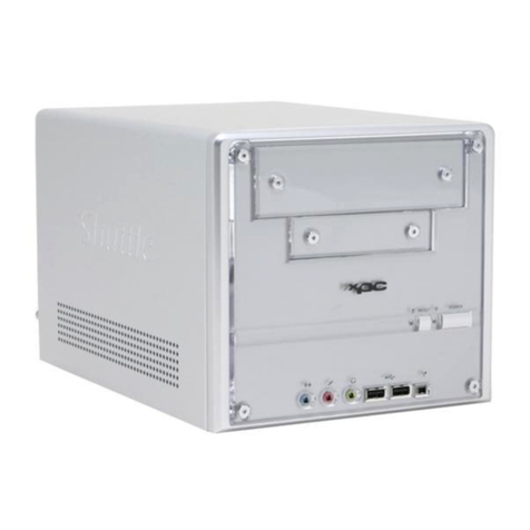
  9. Shuttle K45 User manual

Shuttle K45 User manual

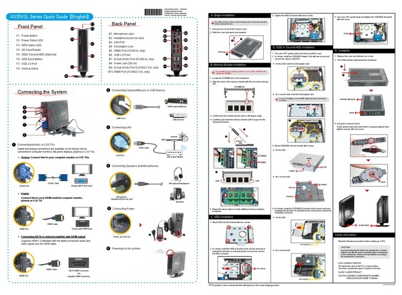
K45 Barebones Quick Guide【 English 】
Jumper Settings
Mainboard illustration
A. Begin Installation
1. Unscrew 3 thumbscrews of
the chassis cover.
2. Slide the cover backwards and upwards.
B. CPU Installation
Note: For safety reasons, please ensure that the power cord is
disconnected before opening the case.
1. Unfasten the ICETM Cooling Module thumbscrews on the back of the
chassis.
1. Unlock the DIMM latch.
2. Align the DDR2 module’s cutout with the DIMM slot notch.
Slide the DDR2 module into the DIMM slot.
D. DDR2 Installation
3. Check that the latches are closed, and the DDR2 modules are firmly
installed.
4. Connect the Serial ATA and power cables to the HDD.
E. HDD Installation
Serial ATA Cable
Serial ATA Power Cable
1. Slide the hard disk drive (HDD) into the chassis.
1. Unfasten expansion slot bracket screws.
Remove the back panel bracket and put the bracket aside.
F. Accessories Installation
2. Install the PCI card into the PCI slot (Optional).
1. Replace the cover and refasten the thumbscrews.
G. Complete
2. Complete.
3. Secure the bracket.
PCI slot
PAR-MA3140-H007
Note: Please load the optimized BIOS values.
Cutout
Latch Latch
Notch
Front panel
Back panel
Note: Failure to correctly align the CPU and socket can result in
damage to the CPU.
Note: Please do not use too much Heatsink compound.
LGA775 Package CPU Socket
Two 240 pins DDR2 DIMM Slots
Power Connector- JP5
One IDE Slot- IDE1
USB Headers- USB3 ,4
Line-In/Front-Out/MIC-In Ports
LAN & USB2.0 (x2) Ports
ATX Power Connector-ATX1
One PCI Slot (Optional)
ATX Power Connector-ATX2
ITE 8718F-S Chipset
Serial ATA- SATA 1,2
USB2.0 (x2) Ports
ICH7 Chipset
Parallel & COM & VGA Ports
PS/2 K/B & M/S Ports
Triangle Markings
Lever
Fan Connector
Note: Repeat to install additional DDR2 modules if desired.
Intel 945GC Chipset
LThe product’s color will depend upon the actually shipping product.
FAN Connector- FAN2
7. Spread an even layer of thermal
compound on the CPU die.
3. Remove the ICETM Cooling Module from the chassis and put it aside.
5. Orientate the CPU and socket, aligning the yellow triangle on the
cornerof the CPU with the triangle on the socket. Making sure the
CPU is perfectly horizontal, insert the CPU into the socket. Close
the load plate, lower the CPU socket lever and lock in place.
6. Remove the protective socket cover.
4. First unlock and raise the socket lever, lift the metal load plate on the
CPU socket.
Note: This 775 pin socket is fragile and easily damaged. Always use
extreme care when installing a CPU and limit the number of
times that you remove or change the CPU.
FAN Connector- FAN1
Front Panel Connector- JP8
Clear CMOS Header- JP9
Note: Please refer to the user guide of the Intel CPU FAN you bought
to install the fan.
1. Screw the Intel CPU FAN to the mainboard and connect the fan
connector.
3. Plug the Serial ATA cable to the SATA1/SATA2 header.
C. FAN Installation
2. Fasten the four side screws.
1
2
1
2
LGA775 Processor
2. Unfasten the four ICETM Cooling Module attachment screws and
unplug the fan connector.
Fan Connector
1
2
3
4
Note: Please make sure to secure the screws on each side.
F1. Power Switch
F2. Power LED
F3. HDD LED
F3
F1
B1
B2
B11
B5 B7B4 B6 B9
B1. AC Power Socket
B2. PS/2 Mouse Port
B3. PS/2 Keyboard Port
B4. COM Port
B5. Parallel Port
B6. VGA Port
B7. USB Port
B8. LAN Port
B9. MIC-In Port
B10. Front-Out (L/R) Port
B11. Line-In Port
B3
B8
B10
BIOS Connector
F2
Pin Assignments (JP5):
1=HDLED_PU
2=GRNLEDA
3=-HD_LED
4=GRNLEDB
5=BT_SEL
6=-PWRSW
7=GND
8=GND
9=NC
10=KEY
Power
Connector
C6
Fan Connectors
Ground
SPEED_SENSE
PWM_CRTL
+12V
FAN1/FAN2
C2
Clear CMOS Header
Pin Assignments (JP9):
1=RTC_RST-
2=-RTCRST
3=-RTCBTN
Pin1-2 (Default) Pin2-3 (Clear CMOS)
C4
Pin Assignments:
1=SPI_CS0-
2=SPI_MISO
3=SPI_WP-
4=GND
5=SPI_MOSI
6=SPI_CLK
7=SPI_HOLD-
8=SPI_VDD
BIOS Connector
1
2
3
4
8
7
6
5
C5
1 3 5 7 9
2 4 6 8 10
Front Panel Connector
Pin Assignments (JP8):
1=MIC2_L
2=AGND
3=MIC2_R
4=FRONT CTL
5=LINE2-R
6=SENSE1_RETURN
7=FRONT_SENSE
8=NC
9=LINE2-L
10=SENSE2_RETURN
C1
USB
Connector
s
USB4
USB3
Pin Assignments (USB3):
1=USBPW3
2=USBPW3
3=USBP2N
4=USBP3N
5=USBP2P
6=USBP3P
7=GND
8=GND
9=KEY
10=GND
Pin Assignments (USB4):
1=USBPW4
2=USBPW4
3=USBP6N
4=USBP7N
5=USBP6P
6=USBP7P
7=GND
8=GND
9=KEY
10=GND
C3
C6
C5
C3
C2
C1
C2
C4
Note: If your xpc has ICETM Cooling Module ( for K45B, K45W,
K45L, K45R models only ), proceed to step1~3.
Remove the ICETM Cooling Module first.
Note: If you are installing the Intel CPU FAN, proceed to step1.
If you are installing the ICETM Cooling Module (for K45B,
K45W, K45L, K45R models only), proceed to step2~4.
2. Screw the ICETM Cooling Module to the mainboard. Note to press down
on the opposite diagonal corner while tightening each screw.
3. Connect the fan connector.
1
2
3
4
Fan Connector
4. Fasten the ICETM Cooling Module to the chassis with the 4 thumbscrews.
1
K45 System Quick Guide【 English 】
F1. Power Switch
F2. Power LED
F3. HDD LED
B1
B2
B11
7
6
B5 B7B4 B6 B9
F3 F1
18
3
2
5
Front panel Back panel
B1. AC Power Socket
B2. PS/2 Mouse Port
B3. PS/2 Keyboard Port
B4. COM Port
B5. Parallel Port
B6. VGA Port
B7. USB Ports
B8. LAN Port
B9. MIC-In Port
B10. Front-Out (L/R) Port
B11. Line-In Port
B3
B8
B10
8
123 4
5
6
7
Customize Your Front Panel【 English 】
Unfasten the front panel by removing
the four screws.
2
3
4
5
6
Remove both the transparent glass
and the image.
Align and correspond the transparent
glass and new image to screw holes
on the front of the machine.
Carefully screw back the four screws.
Insert the new image and cover back
the transparent glass on top. Congraduation, you have your
customized image now.
Connecting Power
(AC Power Socket)
Connecting USB device
(USB Ports)
Connecting Speaker
(Front-Out Port)
Connecting Monitor
(VGA Port)
Connecting Keyboard and Mouse
(PS/2 Mouse, PS/2 Keyboard Port)
4Connecting the Network
(LAN Port)
Powering on the system
(Power Switch)
Connecting Headphone & Microphone
(Front-Out & MIC-In Port)
Support 5.1 channels
F2

Other Shuttle Desktop manuals

Shuttle XPC Barebone SH67H3 Owner's manual

Shuttle

Shuttle XPC Barebone SH67H3 Owner's manual

Shuttle NC10U5 User manual

Shuttle

Shuttle NC10U5 User manual

Shuttle XPC M1000 User manual

Shuttle

Shuttle XPC M1000 User manual

Shuttle XS35V4 Series User manual

Shuttle

Shuttle XS35V4 Series User manual

Shuttle SX48P2 E User manual

Shuttle

Shuttle SX48P2 E User manual

Shuttle XPC SD11G5 User manual

Shuttle

Shuttle XPC SD11G5 User manual

Shuttle XH510G00.104 User manual

Shuttle

Shuttle XH510G00.104 User manual

Shuttle DH02U User manual

Shuttle

Shuttle DH02U User manual

Shuttle XPC SD39P2 User manual

Shuttle

Shuttle XPC SD39P2 User manual

Shuttle Prima XPC Barebone SX38P2 Pro Owner's manual

Shuttle

Shuttle Prima XPC Barebone SX38P2 Pro Owner's manual

Shuttle XPC SD36G5M User manual

Shuttle

Shuttle XPC SD36G5M User manual

Shuttle DS61 User manual

Shuttle

Shuttle DS61 User manual

Shuttle D10 User manual

Shuttle

Shuttle D10 User manual

Shuttle DH410 Series User manual

Shuttle

Shuttle DH410 Series User manual

Shuttle XS35GT User manual

Shuttle

Shuttle XS35GT User manual

Shuttle DS10U Series User manual

Shuttle

Shuttle DS10U Series User manual

Shuttle SH61R5 Series User manual

Shuttle

Shuttle SH61R5 Series User manual

Shuttle DS50U User manual

Shuttle

Shuttle DS50U User manual

Shuttle Prima XPC Barebone SX48P2 Deluxe User manual

Shuttle

Shuttle Prima XPC Barebone SX48P2 Deluxe User manual

Shuttle XH110G Series User manual

Shuttle

Shuttle XH110G Series User manual

Shuttle XPC SB87G5 User manual

Shuttle

Shuttle XPC SB87G5 User manual

Shuttle SX79R5 User manual

Shuttle

Shuttle SX79R5 User manual

Shuttle XC60J User manual

Shuttle

Shuttle XC60J User manual

Shuttle XPC slim XH510G2 User manual

Shuttle

Shuttle XPC slim XH510G2 User manual

Popular Desktop manuals by other brands

HP Compaq Presario supplementary guide

HP

HP Compaq Presario supplementary guide

HP ZBook x2 manual

HP

HP ZBook x2 manual

CompuLab Fitlet FC-OPLN installation instructions

CompuLab

CompuLab Fitlet FC-OPLN installation instructions

Lenovo ThinkSystem ST50 V2 quick start

Lenovo

Lenovo ThinkSystem ST50 V2 quick start

Lenovo J200 Hardware

Lenovo

Lenovo J200 Hardware

LG PC100 Easy setup guide

LG

LG PC100 Easy setup guide

AXIOMTEK AIE900-902-FL Series user manual

AXIOMTEK

AXIOMTEK AIE900-902-FL Series user manual

Lenovo [ideacentre 510A-15ARR/Energy Star Hardware Maintenance Manual

Lenovo

Lenovo [ideacentre 510A-15ARR/Energy Star Hardware Maintenance Manual

HP Compaq d228 MT Hardware reference guide

HP

HP Compaq d228 MT Hardware reference guide

Compaq Evo Workstation W4000 Hardware reference guide

Compaq

Compaq Evo Workstation W4000 Hardware reference guide

HP Workstation Z800 Configuration guidelines

HP

HP Workstation Z800 Configuration guidelines

Energy Star Xi3 NUC Lear instruction manual

Energy Star

Energy Star Xi3 NUC Lear instruction manual

Panasonic FZ-G2 Series operating instructions

Panasonic

Panasonic FZ-G2 Series operating instructions

BT Pavilion a6210.uk Specifications

BT

BT Pavilion a6210.uk Specifications

HP Compaq dc5700 MT reference guide

HP

HP Compaq dc5700 MT reference guide

HP Workstation x2100 install guide

HP

HP Workstation x2100 install guide

Sintrones VBOX-3200 user manual

Sintrones

Sintrones VBOX-3200 user manual

Asus AAEON RTC-1010M user manual

Asus

Asus AAEON RTC-1010M user manual

manuals.online logo
manuals.online logoBrands
  • About & Mission
  • Contact us
  • Privacy Policy
  • Terms and Conditions

Copyright 2025 Manuals.Online. All Rights Reserved.