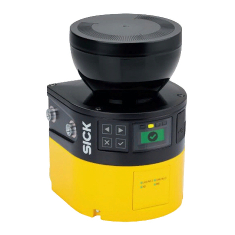
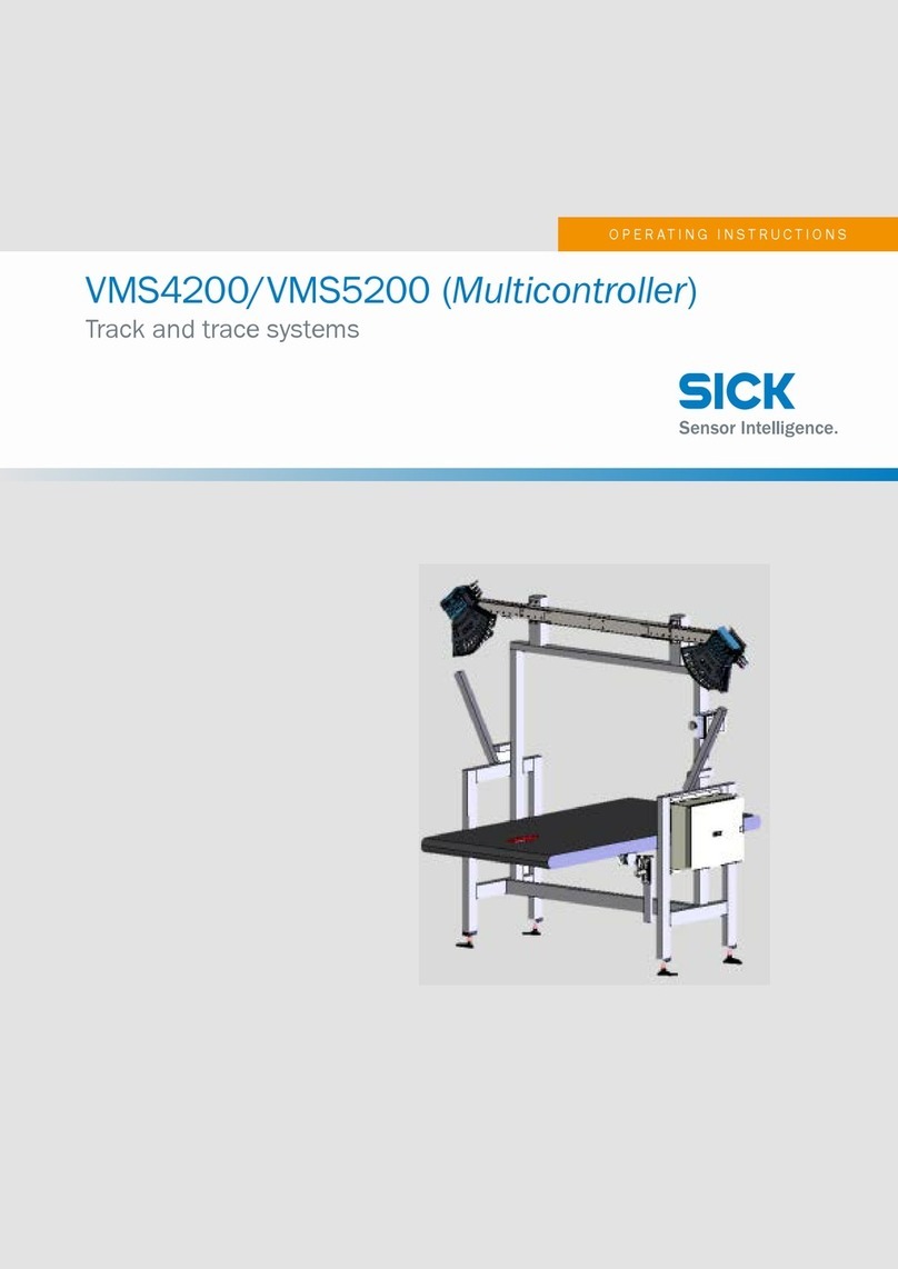
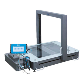
SICK VMS410 User manual

OPERATING INSTRUCTIONS
The benchmark for reliable object dimensioning
VMS410/VMS510
Volume Measurement System

2©SICK AG · Division Auto Ident · Germany · All rights reserved 8010592/R787/2007-06-15
Software versions Operating Instructions
Volume measurement system VMS410/510
Software versions described
ATTENTION
The VMS volume measurement system is intended exclusively for use in industrial
environments. When used in residential areas, the device can cause radio interference.
Software/tool Function Status
VMD410,1000 Firmware V 2.00 or higher
VMD510,1000 Firmware V 2.00 or higher
Device description VMD410 Device specific software
module for SOPAS
V01.02.00 or higher
Device description VMD510 Device specific software
module for SOPAS
V01.02.00 or higher
SOPAS Configuration software V 02.12 or higher
Copyright
Copyright © 2007
SICK AG Waldkirch
Auto Ident, Werk Reute
Nimburger Straße 11
79276 Reute
Germany
Trademarks
Windows 98, Windows NT 4.0, Windows 2000, Windows XP and Internet Explorer are
registered trademarks of Microsoft Corporation in the USA and other countries.
Version of the operating instructions
The newest version of these operating instructions can be obtained as PDF at
www.sick.com.

8010592/R787/2007-06-15 © SICK AG · Division Auto Ident · Germany · All rights reserved 3
Operating Instructions
VMS410/510
Quick Finder
Getting started …
•Delivery
–Section 3.1 “Delivery” on page 18
•WARNING!
–Chapter 2 “For your safety” on page 13
•Mounting and adjusting the device
–Chapter 4 “Mounting” on page 33
•Connecting the device electrically
–Chapter 5 “Electrical installation” on page 35
•Familiarisation with the device and its functions in general
–Chapter 3 “Product description” on page 18
–Chapter 3.8 “Data interfaces specification” on page 29
–Chapter 10 “Technical specifications” on page 53
•Setting the device up for measurement
–Chapter 7 “Configuration and adjustment” on page 42
•Help with resolving problems
–Chapter 9 “Troubleshooting” on page 52
•Where is what?
–“Table of contents” on page 5

4©SICK AG · Division Auto Ident · Germany · All rights reserved 8010592/R787/2007-06-15
Quick Finder Operating Instructions
Volume measurement system VMS410/510
Installation steps (overview)
1. Check delivery for completeness.
2. Mount the VMD over the conveyor system.
3. Connect VMD to voltage supply.
4. Switch on PC and start Windows (minimum requirement: Windows 98).
5. Install enclosed SOPAS configuration software from CD-ROM on PC.
6. Connect the PC to the VMD using the Ethernet interface.
7. Start the SOPAS configuration software user interface and add a new project.
ATTENTION
Don’t switch off the voltage supply during configuration!
Switching off the voltage supply during configuration causes all parameters already
configured to be lost.
8. Configuration of the scan assistant (SCAN ASSISTANT file card, CONFIGURATION button).
Enter the IP address for the VMD and check setting for the CoLa dialect.
9. Scan for devices connected (SCAN ASSISTANT file card, SCAN button) and add the VMD to
the SOPAS project tree.
10. From the EXTRAS menu select the LOGIN DEVICE command and log in to the system as
AUTHORISED CLIENT using the password “client”.
11. Deactivate preset laser control settings during adjustment (PROJECT TREE,
VMDX10_XX00, PARAMETER, DIGITAL INPUTS/TRIGGER,area LASER CONTROL).
12. Adjust the VMD so that the middle of the sensor is over the middle of the conveyor
system and the beam is normally incident on the conveyor system.
13. Configure the position of the VMDs with the aid of the installation setup (VMDX10_XX00
menu, COMMISSIONING, START INSTALLATION SETUP).
14. Configure the VMD with the aid of the options on the PROJECT TREE,VMDX10_XX00,
PARAMETER for the desired application.
15. Checking the measurement area of the system (PROJECT TREE,VMDX10_XX00, MONITOR).
16. Reactivate the laser control (PROJECT TREE,VMDX10_XX00, PARAMETER, DIGITAL INPUTS/
TRIGGER,area LASER CONTROL).
17. Test the configuration under real conditions.
Recommendation Use the graphic scan view in SOPAS to verify the generated measured values and to
verify the measurement area online. During this process, note that the monitor cannot
display the data in real-time and therefore does not display all measured values.
18. If necessary, correct and optimise the parameters set.
19. Save parameter record as a configuration file (extension “*.spr”) (menu PROJECT, SAVE
PROJECT AS).
20. Save parameter set permanently to the VMD (menu VMDX10_XX00, PARAMETER, SAVE
PERMANENT). The parameter set is then saved on the EEPROM.
21. The VMS410/510 is ready for use with the application-specific configuration.

8010592/R787/2007-06-15 © SICK AG · Division Auto Ident · Germany · All rights reserved 5
Operating Instructions
VMS410/510
Contents
Table of contents
1 About this document ............................................................................................. 11
1.1 Function of this document ........................................................................................ 11
1.2 Target group .............................................................................................................. 11
1.2.1 Mounting, electrical installation, maintenance and replacement ........11
1.2.2 Commissioning, operation and configuration ........................................ 11
1.3 Depth of information ................................................................................................. 11
1.4 Symbology used ........................................................................................................ 12
2 For your safety ....................................................................................................... 13
2.1 Authorised personnel ................................................................................................ 13
2.1.1 Mounting and maintenance .................................................................... 13
2.1.2 Electrical installation and replacement .................................................. 13
2.1.3 Commissioning, operation and configuration ........................................ 13
2.2 Applications of the device ........................................................................................ 13
2.3 Correct use ................................................................................................................ 14
2.4 General safety notes and protective measures ...................................................... 14
2.5 Quick stop and Quick restart .................................................................................... 16
2.5.1 Switch off VMS ......................................................................................... 16
2.5.2 Switch VMS back on ................................................................................. 16
2.6 Environmental protection ......................................................................................... 17
2.6.1 Power consumption ................................................................................. 17
2.6.2 Disposal after final de-commissioning ................................................... 17
3 Product description ............................................................................................... 18
3.1 Delivery ...................................................................................................................... 18
3.2 Special features ........................................................................................................ 18
3.3 Operating principle of the device .............................................................................18
3.3.1 Operating principle VMS .......................................................................... 18
3.3.2 Measuring modes .................................................................................... 19
3.3.3 Evaluation of the RIS values ....................................................................22
3.3.4 Camera focusing ...................................................................................... 22
3.3.5 Increment settings ................................................................................... 22
3.4 Planning ..................................................................................................................... 23
3.4.1 System requirements for the VMS volume measurement system ....... 23
3.4.2 Requirements on the conveyor system .................................................. 23
3.4.3 Object specifications ................................................................................ 24
3.4.4 Mounting requirements ........................................................................... 24
3.5 Standardisation of the VMS510 .............................................................................. 26
3.6 Scale intervals of the VMS ........................................................................................ 28
3.6.1 Dynamic scale intervals ........................................................................... 28
3.7 Status indicators ....................................................................................................... 29
3.8 Data interfaces specification ................................................................................... 29
3.8.1 Terminal interface .................................................................................... 29
3.8.2 Host interface ........................................................................................... 30
3.8.3 Ethernet interface .................................................................................... 32
3.8.4 CAN interface ............................................................................................ 32

6©SICK AG · Division Auto Ident · Germany · All rights reserved 8010592/R787/2007-06-15
Contents Operating Instructions
Volume measurement system VMS410/510
4 Mounting ................................................................................................................33
4.1 Overview of the mounting steps .............................................................................. 33
4.2 Preparations for mounting ....................................................................................... 33
4.2.1 Components to be mounted ................................................................... 33
4.2.2 Place material at hand ............................................................................ 33
4.2.3 Mounting accessories ............................................................................. 33
4.3 Mounting the VMD .................................................................................................... 34
4.4 Dismounting the system .......................................................................................... 34
5 Electrical installation ............................................................................................35
5.1 Overview of the installation steps ........................................................................... 35
5.2 Electrical connections and cables ........................................................................... 35
5.3 Pin assignment of the connections ......................................................................... 36
5.3.1 “Ethernet” connection ............................................................................. 36
5.3.2 “System” connection ............................................................................... 36
5.3.3 “I/O” connection ...................................................................................... 37
5.3.4 “Serial” connection .................................................................................. 38
5.4 Connection via the plug cover ................................................................................. 39
5.5 Performing electrical installation ............................................................................. 39
5.5.1 Overview of the connection steps .......................................................... 39
5.5.2 Equipment ................................................................................................ 39
5.5.3 Connecting the voltage supply ................................................................ 39
5.5.4 Connecting the PC ................................................................................... 40
6 Commissioning ......................................................................................................41
7 Configuration and adjustment .............................................................................42
7.1 Preparing the configuration and adjustment .......................................................... 42
7.2 Mechanically adjusting VMD .................................................................................... 43
7.2.1 Adjustment above a conveyor system .................................................... 43
7.2.2 Adjustment of the angle ....................................................................... 44
7.2.3 Adjustment of the angle ....................................................................... 44
7.2.4 Adjustment of the angle ...................................................................... 45
7.3 Define the coordinates and the angle gamma using the installation setup ........ 46
7.3.1 Defining the angle ,the Y and the Z coordinates ................................ 46
7.3.2 Defining the transporting surface ........................................................... 46
7.3.3 Defining the Y coordinate ........................................................................ 47
7.3.4 Applying the parameters ......................................................................... 48
7.4 Defining the scan settings, encoder settings
and the measured data message in SOPAS ........................................................... 48
7.4.1 Configuring the scan settings ................................................................. 48
7.4.2 Encoder settings ...................................................................................... 48
7.4.3 Measured data message ........................................................................ 49
7.5 Testing of the configuration ..................................................................................... 49
7.5.1 Display of the measurement results ...................................................... 49
7.5.2 VMS results list ........................................................................................ 49
7.5.3 Noise statistics ......................................................................................... 49
7.5.4 Scan view ................................................................................................. 49
7.5.5 3D object view ......................................................................................... 49
8 Maintenance ..........................................................................................................50
8.1 Maintenance during operation ................................................................................ 50
8.2 Disposal ..................................................................................................................... 51
8.3 Replacement of a system or replacement of components .................................... 51
8010592/R787/2007-06-15 © SICK AG · Division Auto Ident · Germany · All rights reserved 7
Operating Instructions
VMS410/510
Contents
9 Troubleshooting .................................................................................................... 52
9.1 In the event of faults or errors .................................................................................. 52
9.2 Error on beam generation ........................................................................................ 52
9.3 Detailed error analysis .............................................................................................. 52
9.3.1 Query system status ................................................................................ 52
9.3.2 Logging data during operation ................................................................ 52
10 Technical specifications ....................................................................................... 53
10.1 Data sheet VMS410/510 volume measurement system ...................................... 53
10.2 Dimensional drawings .............................................................................................. 55
10.2.1 Dimensional drawing VMD volume measurement system ................... 55
10.2.2 Dimensional drawing mounting kit for VMD ........................................... 56
11 Annex ..................................................................................................................... 57
11.1 Overview of the annexes ........................................................................................... 57
11.2 Control messages reference .................................................................................... 57
11.2.1 Object start ............................................................................................... 58
11.2.2 Object end ................................................................................................ 58
11.2.3 Heartbeat .................................................................................................. 58
11.2.4 Stand-by .................................................................................................... 59
11.2.5 Measuring mode ...................................................................................... 59
11.3 Measured data message reference ......................................................................... 61
11.3.1 Basic measured data message (metric values) ..................................... 61
11.3.2 Basic measured data message (values in inch) .................................... 62
11.3.3 Basic measured data message 2 (metric values) ................................. 63
11.3.4 Basic measured data message 2 (values in inch) ................................. 64
11.3.5 Extended measured data message (metric values) .............................. 66
11.3.6 Extended measured data message (values in inch) .............................. 67
11.3.7 Extended measured data message 2 (metric values) ........................... 68
11.3.8 Extended measured data message 2 (values in inch) .......................... 69
11.4 Ordering information ................................................................................................. 70
11.4.1 Available systems ..................................................................................... 70
11.4.2 Accessories/spare parts .......................................................................... 70
11.5 Glossary ..................................................................................................................... 72
11.6 Illustration containing the EC Declaration of Conformity .......................................74
11.7 Illustration of the MID conformity certificate ........................................................... 75
11.8 Illustration of the OIML conformity certificate ......................................................... 76

8©SICK AG · Division Auto Ident · Germany · All rights reserved 8010592/R787/2007-06-15
Figures and tables Operating Instructions
Volume measurement system VMS410/510
Abbreviations
BCC Block Character Check
CAN Controller Area Network = standardised fieldbus system with message-based protocol for
exchanging data
CCD Charge-coupled Device, CCD camera = line camera, e.g. for reading bar-codes
CS Checksum
EEPROM Electrically Erasable Programmable Read-only Memory
HTML Hypertext Markup Language = page description language on the Internet
LED Light Emitting Diode
RAM Random Access Memory = volatile memory with direct access
RIS Remission Information System
ROM Read-only memory (permanent)
SOPAS SICK OPEN PORTAL for APPLICATION and SYSTEMS Engineering Tool = configuration
software for the configuration of the VMS
SST Interface
VMD Volume Measurement Device = scanner head
VMS Volume Measurement System = SICK AG volume measurement system

8010592/R787/2007-06-15 © SICK AG · Division Auto Ident · Germany · All rights reserved 9
Operating Instructions
VMS410/510
Figures and tables
Tables
Tab. 1: Minimum and maximum object dimensions ....................................................... 24
Tab. 2: Minimum distance between the top edge of the object
and the measurement zero point ......................................................................... 25
Tab. 3: Certified, measurable object sizes at 1.2 m/s (236.22 ft/min)
conveyor velocity ................................................................................................... 26
Tab. 4: Certified, measurable object sizes at 2 m/s (393.7 ft/min)
conveyor velocity ................................................................................................... 26
Tab. 5: Typical scale intervals ........................................................................................... 28
Tab. 6: Significance of the LEDs ....................................................................................... 29
Tab. 7: Frame for the messages on the host interface ................................................... 30
Tab. 8: Example rounded measured results .................................................................... 31
Tab. 9: Function of the electric connections of the VMS ................................................ 35
Tab. 10: Pin assignment of the “Ethernet” connection ..................................................... 36
Tab. 11: Pin assignment of the “System” connection ....................................................... 36
Tab. 12: Pin assignment of the “I/O” connection .............................................................. 37
Tab. 13: Pin assignment of the “Serial” connection .......................................................... 38
Tab. 14: VMS data sheet ..................................................................................................... 53
Tab. 15: Syntax error or logical errors ................................................................................. 57
Tab. 16: Available systems .................................................................................................. 70
Tab. 17: General accessories .............................................................................................. 70
Tab. 18: Interface sets ......................................................................................................... 70
Tab. 19: Plug cover sets ....................................................................................................... 71
Tab. 20: Accessories for plug covers .................................................................................. 71
Tab. 21: Spare parts measuring head ................................................................................ 71

10 ©SICK AG · Division Auto Ident · Germany · All rights reserved 8010592/R787/2007-06-15
Figures and tables Operating Instructions
Volume measurement system VMS410/510
Figures
Fig. 1: Laser output opening .............................................................................................15
Fig. 2: Laser warning labels on the VMS .........................................................................16
Fig. 3: Illustration of a VMS with frame above a conveyor system ................................19
Fig. 4: Free running mode .................................................................................................19
Fig. 5: Triggered measurement ........................................................................................20
Fig. 6: Laser off distance ..................................................................................................21
Fig. 7: Working area of the VMS volume measurement system ....................................23
Fig. 8: Illustration of a VMS above a conveyor system ...................................................24
Fig. 9: Illustration of the mounting height .......................................................................25
Fig. 10: Certification label for the VMS510 to be fitted ....................................................27
Fig. 11: Possible places where the seals could be attached to the VMD510 .................27
Fig. 12: Output timing diagram ...........................................................................................31
Fig. 13: Overview of the mounting above a conveyor system ..........................................33
Fig. 14: Mounting of the VMD above a conveyor system ..................................................34
Fig. 15: Position of the electric connections of the VMS ..................................................35
Fig. 16: Wiring of the digital input ......................................................................................37
Fig. 17: Wiring of the RS,232 or RS,422 ...........................................................................38
Fig. 18: Example of a plug cover ........................................................................................39
Fig. 19: Mounting kit for VMD .............................................................................................43
Fig. 20: Adjustment above a conveyor system ..................................................................43
Fig. 21: Adjustment of the angle ......................................................................................44
Fig. 22: Adjustment of the angle .....................................................................................44
Fig. 23: Screws on the mounting kit for the adjustment of the angle ..........................45
Fig. 24: Adjustment of the angle .....................................................................................45
Fig. 25: Angle and Y coordinate and Z coordinate ..........................................................46
Fig. 26: Example scanned conveyor system ......................................................................47
Fig. 27: Entry of the distance from the zero point .............................................................47
Fig. 28: Scanned test object ...............................................................................................48
Fig. 29: Dimensional drawing VMD ....................................................................................55
Fig. 30: Dimensional drawing mounting kit for VMD ........................................................56
Fig. 31: Illustration containing the EC Declaration of Conformity ....................................74
Fig. 32: Illustration of the MID conformity certificate .......................................................75
Fig. 33: Illustration of the OIML conformity certificate ......................................................76

Operating Instructions
VMS410/510
About this document
8010592/R787/2007-06-15 © SICK AG · Division Auto Ident · Germany · All rights reserved 11
Chapter 1
1About this document
Please read this chapter carefully before working with this documentation and the
VMS410/510 volume measurement system.
1.1 Function of this document
These operating instructions are designed to address the technical personnel in regards
to safe mounting, configuration, electrical installation, commissioning, operation and
maintenance of the VMS volume measurement system.
1.2 Target group
The intended audience for this document is people in the following positions:
1.2.1 Mounting, electrical installation, maintenance and replacement
Factory electricians and service engineers
1.2.2 Commissioning, operation and configuration
Technicians and engineers
1.3 Depth of information
Note The VMS410 as well as the VMS510 will be referred to as “VMS” in the following.
These operating instructions contain the following information on the VMS:
•mounting
•electrical installation
•commissioning and configuration
•maintenance
•fault, error diagnosis and troubleshooting
•ordering information
•conformity and approval
Planning and using measurement systems such as the VMS also require specific technical
skills which are not detailed in this documentation.
The VMS is configured on-site for the related application using the SOPAS configuration
software. How to use the software is described in Chapter 7 “Configuration and adjustment”
on page 42.
When operating the VMS volume measurement system, the national, local and statutory
rules and regulations must be observed.
Note Please refer also to the VMS information in the Internet at www.sick.com.

12 ©SICK AG · Division Auto Ident · Germany · All rights reserved 8010592/R787/2007-06-15
Chapter 1About this document Operating Instructions
Volume measurement system VMS410/510
1.4 Symbology used
Reference Text in italics indicates a reference to more detailed information.
Recommendation Recommendations are designed to give you assistance in the decision-making process with
respect to a certain function or a technical measure.
Note Refer to notes for special features of the device.
Explanation Explanations provide background knowledge on technical relationships.
MENU COMMAND This typeface indicates a term in the SOPAS user interface.
Terminal output This typeface indicates messages that the VMS outputs via its terminal interface.
Take action … Instructions for taking action are shown by an arrow. Read carefully and follow the
instructions for action.
This symbol refers to additionally available documentation.
ATTENTION
Warning!
Awarning indicates an actual or potential hazard. They are designed to help you to prevent
accidents and to protect the device from being damaged.
Read carefully and follow the warning notices!
Software notes show you where the related setting can be made in the SOPAS configuration
software.

Operating Instructions
VMS410/510
For your safety
8010592/R787/2007-06-15 © SICK AG · Division Auto Ident · Germany · All rights reserved 13
Chapter 2
2For your safety
This chapter deals with your own safety and the safety of the equipment operators.
Please read this chapter carefully before working with the VMS or with the conveyor
system equipped with the VMS.
2.1 Authorised personnel
The VMS volume measurement system must be installed, commissioned and serviced only
by adequately qualified personnel.
The following qualifications are necessary for the various tasks:
2.1.1 Mounting and maintenance
•basic technical training
•knowledge of the current safety regulations in the workplace
2.1.2 Electrical installation and replacement
•practical electrical training
•knowledge of current electrical safety regulations
•knowledge on the use and operation of devices in the related application (e.g.
conveyors)
2.1.3 Commissioning, operation and configuration
•knowledge on the use and operation of devices in the related application (e.g.
conveyors)
•knowledge on the software and hardware environment in the related application (e.g.
conveyors)
•basic knowledge of the Windows operating system
•basic knowledge of the usage of an HTML browser (e.g. Internet Explorer)
•basic knowledge of data transmission
2.2 Applications of the device
The VMS volume measurement system is intended exclusively for use in industrial
environments. When used in residential areas, the device can cause radio interference.
It measures cuboid objects on flat conveyor systems.
•The VMS410 determines length, width and height, and calculates from this information
the volume of the smallest enclosing cuboid, the box volume.
•The VMS510 determines length, width and height.
This information is passed by the related system over a data interface to the customer’s
computer for further processing.

14 ©SICK AG · Division Auto Ident · Germany · All rights reserved 8010592/R787/2007-06-15
Chapter 2For your safety Operating Instructions
Volume measurement system VMS410/510
2.3 Correct use
The VMS volume measurement system must be used only as defined in Section 2.2
“Applications of the device” on page 13.It is only allowed to be used by qualified personnel
and only in industrial environments on the conveyor system on which it has been installed
and initially commissioned by specialist personnel in accordance with these operating
instructions.
If the device is used for any other purpose, opened or modified in any way — also during
mounting and installation — any warranty claim against SICK AG shall become void.
2.4 General safety notes and protective measures
ATTENTION
Safety notes
Please observe the following items in order to ensure the correct and safe use of the VMS
volume measurement system.
•The notices in these operating instructions (e.g. on use, mounting, installation or
integration into the existing machine controller) must be observed.
•National/international rules and regulations apply to the installation, commissioning,
use and periodic technical inspections of the volume measurement system, in
particular:
– work safety regulations/safety rules
– other relevant health and safety regulations
•Manufacturers and users of the system are responsible for obtaining and observing all
applicable safety regulations and rules.
•The tests must be carried out by specialist personnel or specially qualified and
authorised personnel and must be recorded and documented to ensure that the tests
can be reconstructed and retraced at any time.
•The operating instructions must be made available to the operator of the system where
the VMS volume measurement system is fitted. The operator of the system is to be
instructed in the use of the device by specialist personnel and must be instructed to
read the operating instructions.
ATTENTION
Risk of injury from electrical power!
The VMS volume measurement system is connected to 24 V DC.
Observe the current safety regulations when working on electrical systems.
ATTENTION
The VMS volume measurement system is intended exclusively for use in industrial
environments. When used in residential areas, the device can cause radio interference.

Operating Instructions
VMS410/510
For your safety
8010592/R787/2007-06-15 © SICK AG · Division Auto Ident · Germany · All rights reserved 15
Chapter 2
WARNING
Damage to the eye from laser radiation!
The VMS uses a red laser of class 2. On extended beam exposure, the retina in the eye
may be damaged.
The entire front screen serves as the laser output opening.
Warning — inappropriate use of the VMS can result in hazardous exposure to radiation and
the laser class may be exceeded.
Never look directly into the beam (similar to sunlight).
Do not point the device laser beam at people.
During mounting and adjustment of the VMS, pay attention to possible reflections of the
laser beam on reflective surfaces.
Do not open the housing. (Opening the housing does not interrupt the power to the laser
diode during the read cycle.)
Observe the latest valid version of the laser safety regulations.
Laser output opening
The laser output opening is the front screen of the VMD.
Fig. 1: Laser output opening
Laser power
The laser operates at a wavelength =650 nm (visible red light). The output power of the
laser beam at the laser output opening is max. 7.5 mW.
The radiation emitted is not harmful to the skin.
The VMS corresponds to laser class 2 as per EN 60825-1 (for publication date see laser
warning label on the device). Complies with 21 CFR 1040.10 with the exception of the
deviations as per Laser Notice No. 50, July 26, 2001.
Note When operated with trigger, the laser diode is only switched on when the power on signal is
present and is switched off again with the shut down signal. For continuous data output the
laser diode is continuously switched on.
Laser output opening

16 ©SICK AG · Division Auto Ident · Germany · All rights reserved 8010592/R787/2007-06-15
Chapter 2For your safety Operating Instructions
Volume measurement system VMS410/510
Laser warning label
On the VMS410/510 volume measurement system are several laser warning labels and
laser warning symbols (see Fig. 2).
Fig. 2: Laser warning labels on the VMS
Notes •Prior to commissioning, the warning label in English on the device “LASER LIGHT - DO
NOT STARE INTO BEAM” is to be replaced with a laser warning label in a language
understood by the operators of the system. Laser warning labels in German/English
and French/English are in the delivery. Leave the “CAUTION ...” and “AVOID EXPOSURE
LASER ...” laser warning labels in English.
•If the VMS volume measurement system is installed in a system/a panel mounting such
that the laser warning labels are covered, further warning labels (not in the delivery) are
to be affixed beside the outlet aperture for the laser beam on the system/on the trim
panel!
•The VMS automatically monitors the beam generation and automatically shuts down
the generation of the beam in case of irregularities. In this case the red LED lights up
and the scanner transmits no more measured values.
•No regular maintenance is necessary to ensure the retention of the laser class 2.
2.5 Quick stop and Quick restart
2.5.1 Switch off VMS
Switch off the voltage supply for the VMS or disconnect the supply cable.
The VMS retains parameters stored in the internal, non-volatile memory. Measured values
on the interface are lost.
2.5.2 Switch VMS back on
Switch on the voltage supply for the VMS or reconnect the supply cable.
The VMS re-commences operation with the parameters last saved.

Operating Instructions
VMS410/510
For your safety
8010592/R787/2007-06-15 © SICK AG · Division Auto Ident · Germany · All rights reserved 17
Chapter 2
2.6 Environmental protection
The VMS volume measurement system has been designed to minimise environmental
impact. It uses only a minimum of power.
While working, always act in an environmentally responsible manner. For this reason please
note the following information on disposal.
2.6.1 Power consumption
The VMS consumes max. 25 W of power.
2.6.2 Disposal after final de-commissioning
Always dispose of unserviceable or irreparable devices in compliance with local/
national rules and regulations on waste disposal.
Dispose of all electronic assemblies as hazardous waste. The electronic assemblies are
straightforward to dismantle.
On this topic see Section 8.2 “Disposal” on page 51.
Note SICK AG does not accept any devices returned that have become unusable or are
irreparable.

18 ©SICK AG · Division Auto Ident · Germany · All rights reserved 8010592/R787/2007-06-15
Chapter 3Product description Operating Instructions
Volume measurement system VMS410/510
3Product description
This chapter provides information on the special features and properties of the VMS volume
measurement system. It describes the construction and the operating principle of the
device, in particular the different operating modes.
Note Please read this chapter before mounting, installing and commissioning the device.
3.1 Delivery
The VMS volume measurement system as delivered comprises:
•aVMD volume measurement device
•one mounting kit for mounting and adjusting the VMD (three axes)
•a CD-ROM containing the following:
– SOPAS configuration software
– “VMS Volume Measurement System” operating instructions in German and English
as PDF file
– the freely available “Adobe Acrobat®Reader™” software for reading PDF files
3.2 Special features
•non-contact, active measurement technique
•volume measurement of cuboid objects
•works with a very wide range of surface structures and on various flat conveyor systems
•flexible system configurations
•calculation of the smallest enclosing cuboid (box volume)
•scale interval d 5mm(0.2 in) (in industrial environments, without interference due
to contamination, vibration or extremely low object remission, without slip between
object and conveyor system or temperature drift; for conveyor system velocities up to
1.2 m/s (236.22 ft/min))
•data processing and data output in real-time at a conveyor system velocity of up to 2 m/
s (393.7 ft/min) (achievable scale interval d 10 mm (0.39 in) for length and breadth
as well as d 5mm(0.2 in) for height)
VMS510 volume measurement system
Measurement system certified in accordance with the Measuring Instruments Directive
2004/22/EC (MID) and in accordance with OIML R129 with measured values that can be
standardized (see Fig. 32 on page 75 and Fig. 33 on page 76).
3.3 Operating principle of the device
3.3.1 Operating principle VMS
Determining the distance data
The VMD is installed above the conveyor system and opto-electronically scans the surfaces
of the conveyor system and transported objects. The VMD does not require any reflectors or
position markers. This is an active system with a red laser; it is not necessary to illuminate
the objects. The VMD uses the principle of phase shift (continuous wave).

Operating Instructions
VMS410/510
Product description
8010592/R787/2007-06-15 © SICK AG · Division Auto Ident · Germany · All rights reserved 19
Chapter 3
The VMS volume measurement system measures cuboid objects on flat conveyor systems.
The VMS opto-electronically determines the box volume of the object from its length, width
and height.
Fig. 3: Illustration of a VMS with frame above a conveyor system
Velocity
The velocity of the object is constantly set in the parameters, or can be determined using
an optional incremental encoder.
Resulting volume
The information on the three-dimensional object is available after the acquisition of the
distance data and calculation using the velocity.
•The VMS410 determines length, width and height, and calculates from this information
the volume of the smallest enclosing cuboid, the box volume.
•The VMS510 determines length, width and height.
The data are available for further processing on the interfaces of the VMS.
3.3.2 Measuring modes
The VMS can either operate with a trigger or Free running.
Free running mode
In the free running mode the VMS automatically detects the objects to be detected. The
measurement starts when an object enters the scan line and ends when the object leaves
the scan line. There must be a minimum gap between objects.
Fig. 4: Free running mode
VMD
Object
Scan line

20 ©SICK AG · Division Auto Ident · Germany · All rights reserved 8010592/R787/2007-06-15
Chapter 3Product description Operating Instructions
Volume measurement system VMS410/510
Triggered measurement with gate
With the triggered measurement the start and end of the measurement is defined by a so-
called gate.
Unlike the free running measurement, it is does not matter whether an object enters or
leaves the scan line. There is also no differentiation between multiple objects between the
start and end of the measurement, instead just one measurement is made.
PROJECT TREE,VMDX10_XX00, PARAMETER, DIGITAL INPUTS/TRIGGER,areas TRIGGER SETTINGS and
GATE SETTINGS
Fig. 5: Triggered measurement
The gate in which VMS measures is defined by a trigger source, a distance delay and an
expansion distance .
Digital inputs are available as the trigger source, or software triggers based on messages
can be used.
In the example, the object initialises the measurement by entering the photoelectric switch
(trigger source). Once the distance defined by the distance delay (defined in SOPAS) has
been covered ,the VMS starts the measurement.
An expansion distance, also defined in SOPAS, expands the gate at the start and end .In
this way, e.g. a tolerance can be realised.
Track controlled triggering
For the track controlled triggering described in Fig. 5 an incremental encoder must be
connected and configured. Using this encoder the distance covered by an object is
determined from the conveyor velocity. With track controlled triggering it is not necessary to
take into account different conveyor velocities or a conveyor system stop. The
measurement starts and stops after a defined distance has been covered.
As an alternative, time-controlled triggering can also be configured in SOPAS: PROJECT TREE,
VMDX10_XX00, PARAMETER, DIGITAL INPUTS/TRIGGER,area COMMON SETTINGS
Photoelectric switch as trigger
source
Object
Scan line
VMD
Incremental
encoder
This manual suits for next models
1
Table of contents
Other SICK Measuring Instrument manuals

SICK
SICK FLOWSIC550 User manual

SICK
SICK FLOWSIC600-XT User manual

SICK
SICK MLG-2 Pro User manual

SICK
SICK MLG-2 Prime User manual

SICK
SICK WebChecker MLG-2 User manual

SICK
SICK InspectorP Rack Fine Positioning User manual

SICK
SICK FLOWSIC600 User manual

SICK
SICK DL100 User manual

SICK
SICK GM901 User manual

SICK
SICK GM32-Ex User manual
Popular Measuring Instrument manuals by other brands

Craind Impianti
Craind Impianti KPO Installation, operation and maintenance manual

SMC Networks
SMC Networks PFMV3 Series Operation manual

Doerr
Doerr DANUBIA DRF-600 user manual

CLEAN Instruments
CLEAN Instruments DH200 instruction manual

Metrohm
Metrohm NIRS DS2500 manual

DS Europe
DS Europe Pitagora TSS Series Technical manual