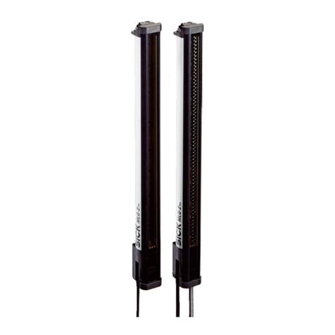
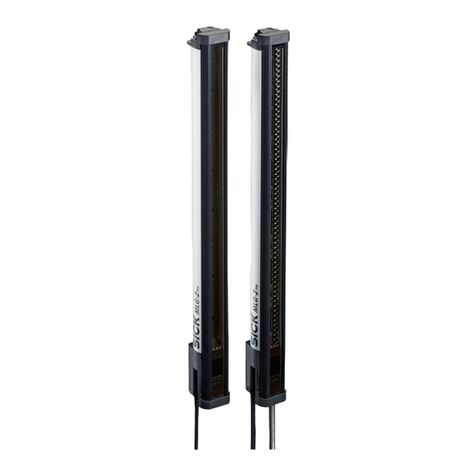
SICK WebChecker MLG-2 User manual

Mon‐
tage‐
anlei‐
tung
2006/42/EC
NO
SAFETY
MOUNTING INSTRUCTION en
IPG69K protective pipe for MLG-2 light grid
There are detailed operating instructions in addition to the mounting instructions
for the MLG-2 light grids. The operating instructions contain all of the informa‐
tion relating to the MLG-2 light grid, such as information on assembly, electrical
connection, settings and technical data. The operating instructions can be down‐
loaded via the internet at: www.mysick.com/de/mlg-2
1 Safety notes
•Read the instructions before commissioning.
•Connection, mounting and settings may only be performed by trained spe‐
cialists.
•Not a safety component in accordance with the EU Machinery Directive.
•When commissioning, protect the device from moisture and contamination.
•These instructions contain information required during the life cycle of the
device.
2 Further notes
NOTE
Mount with additional support brackets depending on the length of the pro‐
tective pipe and the temperature at which it will be used. See the “Dimen‐
sions” figure.
3 Intended use
Installed in the IPG69K protective pipe, the MLG-2 light grids achieve an enclo‐
sure rating of IP 69K. The protective pipe is used to protect the light grid from dust
and spraying water. Suitable for use in the food industry.
4 Scope of delivery and accessories
1
2
3
4
Scope of delivery:
1MLG-2 IP69K protective pipe
Accessoires:
2Support bracket
3 + 4Stainless steel bracket (see the “Accessories” table)
5 Mounting
1.
The two holders (X1 + X2) on top and bottom put on the protective tube,
tighten the screws and assemble at the desired installation location.
2. Install support brackets as follows:
For protective pipe lengths of 1,185 mm and greater: Mount support bracket
(part number 2026849) in the middle of the light grid.
For protective pipe lengths of 1,485 mm and greater and an application
temperature range of –20 °C to +55 °C: Mount support brackets (With a
holder on one side to compensate for the linear expansion. In the middle
with support bracket. Part number: 2026849) evenly along the length of the
light grid. Note the mounting variants.
= =
3. To ensure reliable functionality during operation, the sensitivity has to be
taught in according to the sensing range. For additional information, see the
corresponding operating instructions.
5.1 Mounting variants
a
1
2
3
Y1
Y2 Y1
Y2 Y3
X1X2
a Support bracket
Y Distance between support brackets
Dimensions of IPG69K protective pipe and mounting variants dependent on the
protective pipe length and application temperature range.
8025069.1CU6 / 07.09.2021/de, en MLG-2 IPG69K | SICK 1
8025069.1CU6 / 07.09.2021
www.sick.com
MLG-2 IPG69K
SICK AG
E
rwin-Sick
-Straße 1
D-79183 Waldkirch

Mounting variant Length of protective
pipe
Operating tempera‐
ture range
Accessories
1 With top and bot‐
tom bracket
285 mm -1035 mm –20 °C … +55 °C 4x 2023708 or 4x
2026850
2 With top and bot‐
tom bracket and sup‐
port brackets
1185 mm - 335 mm –20 °C … +55 °C 4x 2023708 or 4x
2026850 and 2x
2026849
1485 mm -
2535 mm
0 °C … +35 °C 4x 2023708 or 4x
2026850 and 2x
2026849
3 With a bracket
and support brackets
1485 mm -
2535 mm
–20 °C … +55 °C 1 x 2023708 or
2026850 and
2026849
6 Electrical installation
When connecting with an extension cable, observe the following note:
NOTE
For 8-pole sensor-actuator cables, the wire colors are not standardized.
Therefore, please observe the pin assignment of the sensor and the cable
in the respective data sheet.
+(L+)
Sync A
- (M)
Sync B
TEST
1
2
3
4
5
Sender Receiver
+(L+)
- (M)
Sync B
Q1/C
3
Q2/In1
3
1
2
3
4
5
6
7
8
Sync A
4
12
5
3
65
1
4
3
2
8
7
PK
VT
OG
BN
WH
BU
BK
GY
BN
WH
BU
BK
GY
PK
BU
RD
WH
BN
GN
YE
GY
1
2
3
4
5
6
7
8
IP69K connecting cable
1
2
1Valid for:
YF2AP8-250PA4XLEAX (2116447),
YF2AP8-020PA4XLEAX (2111888)
2Observe the pin assignment of the sensor and the cable in the respec‐
tive data sheet
3Depending on type
7 Accessories
Part number Type Description
2023708 BEF-2SMMEAES4 4 pieces, holder stainless steel, swiveling, clamp in one
piece and removable
2026850 BEF-2SMMVAES4 4 pieces, holder stainless steel, swiveling, clamp in two
parts
2026849 BEF-2AAADES2 2 pieces, stainless steel support bracket
8 Cleaning
IP69K = Protection against water at high pressure / steam cleaning.
Clean the protective pipe at regular intervals. Observe the following points while
cleaning:
•Do not use any corrosive cleaning agents.
•Do not use any abrasive cleaning agents.
•You can reduce this effect by using an anti-static plastic cleaner (part num‐
ber 5600006) and a SICK lens cloth (part number 4003353).
Proceed as follows when cleaning the protective pipe:
1. Remove any dirt on the protective pipe with plenty of water.
2. Remove any leftover water on the protective pipe.
3. Dry the protective pipe with a clean, lint-free cloth.
9 Maintenance
SICK devices are maintenance-free.
We recommend cleaning the device and checking screwed and plugged connec‐
tions at regular intervals.
No modifications may be made to devices.
10 Disposal
The device must be disposed of according to the applicable country-specific
regulations. Efforts should be made during the disposal process to recycle the
constituent materials (particularly precious metals).
11 IPG69K protective pipe technical data
The protective pipe reduces the operating range of the light grid MLG-2 as speci‐
fied in the following table.
Operating range [m] Sensing range with protective pipe [m]
8,5 6,3
5 3,75
Operating range [m] Sensing range with protective pipe [m]
2 (only MLG-2 with 2.5 mm beam distance) 1,5
Maximum monitoring height 2,400 mm.
Description Value
Enclosure rating IP 69K
Material Protective pipe: PMMA Plexiglas XT Food Contact DoC
Pipe: polypropylene stainless steel 1.4404
Pressure compensation element: VA 1.4305
End caps: stainless steel 1.4404
Cable gland: stainless steel V4A 1.4404 DIN EN 1672-2
Ambient temperature –20 °C … +55 °C
12 IPG69K Dimensions protective pipe and mounting variants
1
2
3
2
5
3
4
56
9 ß
9 ß
8
7
Ø 50 (1.97)
Ø 30.5 (1.2)
Ø 50 (1.97)
Ø 30.5 (1.2)
Ø 50 (1.97)
23 (0.91)
Ø 50 (1.97)
23 (0.91)
392 ±10 (15.45 ±0.39)
M12 5P.
M12 5P./8P.
56 (2.2)
A
B
27 (1.06)
2 (0.08)
Distance A Distance B
2,5-mm-grid A = 94.25 mm 2,5-mm-grid B = 84.7 mm
5-mm-grid A = 9.55 mm 5-mm-grid B = 83.6 mm
10-mm-grid A = 100.5 mm 10-mm-grid B = 83.6 mm
20-mm-grid A = 100.5 mm/
110.5 mm120-mm-grid B = 83.6 mm
25-mm-grid A = 115.5 mm 25-mm-grid B = 83.6 mm
30-mm-grid A = 120.5 mm 30-mm-grid B = 83.6 mm
50-mm-grid A = 140.5 mm 50-mm-grid B = 83.6 mm
1MLG20x-xx40: 100.5 mm
MLG20x-xx80: 110. mm
8025069.1CU6 / 07.09.2021/de, en MLG-2 IPG69K | SICK 2

MONTAGEANLEITUNG de
Schutzrohr IPG69K für Lichtgitter MLG-2
Zusätzlich zur Montageanleitung gibt es die ausführlichen Betriebsanleitungen für
die Lichtgitter MLG-2. Die Betriebsanleitungen umfassen alle Informationen wie
Montage, Elektrischen Anschluss, Einstellungen und technische Daten zum Licht‐
gitter MLG-2. Die Betriebsanleitungen können über das Internet heruntergeladen
werden: www.mysick.com/de/mlg-2
1 Sicherheitshinweise
•Vor der Inbetriebnahme die Anleitung lesen.
•Anschluss, Montage, Einstellungen nur durch Fachpersonal.
•Kein Sicherheitsbauteil nach EU-Maschinenrichtlinie
•Gerät bei Inbetriebnahme vor Feuchte und Verunreinigung schützen.
•Diese Anleitung enthält Informationen, die während des Lebenszyklus des
Geräts notwendig sind.
2 Weitere Hinweise
HINWEIS
Je nach Länge des Schutzrohrs und der Einsatztemperatur das Schutzrohr
mit zusätzlichen Stützhalterungen montieren. Siehe Abbildung „Abmessung“.
3 Bestimmungsgemäße Verwendung
Die Lichtgitter MLG-2 erreichen, in das Schutzrohr IPG69K eingebaut, die Schut‐
zart IP 69K. Das Schutzrohr dient dazu, das Lichtgitter vor Staub und Strahlwas‐
ser zu schützen. Tauglich für die Anwendung in der Lebensmittelindustrie.
4 Lieferumfang und Zubehör
1
2
3
4
Lieferumfang
1Schutzrohr MLG-2 IP69K
Zubehör
2Stützhalterung
3 + 4Edelstahl-Befestigungswinkel (siehe Tabelle "Zubehör")
5 Montage
1.
Die beiden Halter (X1 + X2) oben und unten auf das Schutzrohr aufstecken,
die Schrauben festziehen und am gewünschten Montageort montieren.
2. Stützhalterungen wie folgt montieren:
bei Schutzrohrlängen ab 1185 mm: Stützhalterung (Artikelnummer
2026849) in der Mitte des Lichtgitters montieren.
Bei Schutzrohrlängen ab 1485 mm und einem Einsatztemperaturbereich
von –20 °C bis +55 °C: Stützhalterungen (Mit einem Halter auf einer
Seite, um die Längenausdehnung zu kompensieren. In der Mitte mit Stütz‐
halterung. Artikelnummer 2026849) gleichmäßig über die Lichtgitterlänge
montieren. Montagevariante beachten.
= =
3. Empfindlichkeit einlernen (Teach-in). Für eine betriebssichere Funktion muss
die Empfindlichkeit entsprechend der vorhandenen Reichweite eingelernt
werden. Weitere Informationen siehe entsprechende Betriebsanleitung.
5.1 Montagevarianten
a
1
2
3
Y1
Y2 Y1
Y2 Y3
X1X2
a Stützhalter
Y Abstand zwischen Stützhaltern
Abmessungen Schutzrohr IPG2 und Montagevarianten abhängig von der Schutz‐
rohrlänge und dem Einsatztemperaturbereich.
8025069.1CU6 / 07.09.2021/de, en MLG-2 IPG69K | SICK 3

Montagevariante Schutzrohrlänge Einsatztemperatur‐
bereich
Zubehör
1 Mit oberem und
unterem Befesti‐
gungswinkel
285 mm -1035 mm –20 °C … +55 °C 4x 2023708 oder 4x
2026850
2 Mit oberem und
unterem Befesti‐
gungswinkel und
Stützhalterungen
1185 mm - 335 mm –20 °C … +55 °C 4x 2023708 oder 4x
2026850 und 2x
2026849
1485 mm -
2535 mm
0 °C … +35 °C 4x 2023708 oder 4x
2026850 und 2x
2026849
3 Mit einem Befesti‐
gungswinkel und
Stützhalterungen
1485 mm -
2535 mm
–20 °C … +55 °C 1 x 2023708 oder
2026850 und
2026849
6 Elektrischer Anschluss
Beim Anschluss mit einer Verlängerungsleitung, folgenden Hinweis beachten:
HINWEIS
Bei 8-poligen Sensor-Aktor-Leitungen sind die Aderfarben nicht einheitlich
normiert. Bitte beachten Sie daher die Anschlussbelegung des Sensors und
der Leitung im jeweiligen Datenblatt.
+(L+)
Sync A
- (M)
Sync B
TEST
1
2
3
4
5
Sender Receiver
+(L+)
- (M)
Sync B
Q1/C
3
Q2/In1
3
1
2
3
4
5
6
7
8
Sync A
4
12
5
3
65
1
4
3
2
8
7
PK
VT
OG
BN
WH
BU
BK
GY
BN
WH
BU
BK
GY
PK
BU
RD
WH
BN
GN
YE
GY
1
2
3
4
5
6
7
8
IP69K connecting cable
1
2
1Gültig für:
YF2AP8-250PA4XLEAX (2116447),
YF2AP8-020PA4XLEAX (2111888)
2Die Anschlussbelegung des Sensors und der Leitung im jeweiligen
Datenblatt beachten
3Typabhängig
7 Zubehör
Artikelnummer Typ Beschreibung
2023708 BEF-2SMMEAES4 4 Stück, Halter Edelstahl, schwenkbar, Schelle einteilig
und abnehmbar
2026850 BEF-2SMMVAES4 4 Stück, Halter Edelstahl, schwenkbar, Schelle zweitei‐
lig
2026849 BEF-2AAADES2 2 Stück, Edelstahlstützhalterung
8 Reinigung
IP69K = Schutz gegen Wasser bei Hochdruck-/ Dampfstrahlreinigung
Reinigen Sie das Schutzrohr in regelmäßigen Abständen. Beachten Sie bei der
Reinigung folgende Punkte:
•Kein aggressives Reinigungsmittel verwenden.
•Keine abriebfördernden Reinigungsmittel verwenden.
•Durch statische Aufladung bleiben Staubteilchen am Schutzrohr hängen. Sie
können diesen Effekt mindern, wenn Sie zur Reinigung den antistatischen
Kunststoffreiniger (Artikelnr. 5600006) und das SICK-Optiktuch (Artikelnr.
4003353) verwenden.
Gehen Sie bei der Reinigung des Schutzrohrs wie folgt vor:
1. Verschmutzungen auf dem Schutzrohr mit reichlich Wasser entfernen. Sie
vermeiden so Kratzer auf der Oberfläche.
2. Wasserreste auf Schutzrohr entfernen. Hierzu mit einem sauberen und
leicht feuchten Tuch nachwischen.
3. Schutzrohr mit einem sauberen und fusselfreien Tuch trocknen.
9 Wartung
SICK-Geräte sind wartungsfrei.
Wir empfehlen in regelmäßigen Abständen, das Gerät zu reinigen und Verschrau‐
bungen und Steckverbindungen zu prüfen.
Veränderungen an Geräten dürfen nicht vorgenommen werden.
10 Entsorgung
Die Entsorgung des Geräts hat gemäß den länderspezifisch anwendbaren Vor‐
schriften zu erfolgen. Für die enthaltenen Wertstoffe (insbesondere Edelmetalle)
ist im Rahmen der Entsorgung eine Verwertung anzustreben.
11 Technische Daten Schutzrohr IP69K
Das Schutzrohr verringert die Betriebsreichweite der Lichtgitter MLG-2 nach fol‐
gender Tabelle.
Betriebsreichweite [m] Reichweite mit Schutzrohr [m]
8,5 6,3
5 3,75
2 (nur MLG-2 mit 2,5 mm Strahlabstand) 1,5
Maximale Überwachungshöhe 2.400 mm.
Beschreibung Wert
Schutzart IP 69K
Material Schutzrohr: PMMA Plexiglas XT Food Contact DoC
Leitung: Polypropylen Edelstahl 1.4404
Druckausgleichselement: VA 1.4305
Endkappen: Edelstahl 1.4404
Leitungsverschraubung: Edelstahl V4A 1.4404 DIN EN 1672-2
Umgebungstemperatur –20 °C … +55 °C
12 Abmessungen Schutzrohr IPG69K und Montagevarianten
1
2
3
2
5
3
4
56
9 ß
9 ß
8
7
Ø 50
Ø 30,5
Ø 50
Ø 30,5
Ø 50
23
Ø 50
23
392 ±10
M12 5P.
M12 5P./8P.
56
A
B
27
2
1Ansicht Transmitter
2Transmitter
3Empfänger
4Ansicht Empfänger
5Erster Strahl
6Letzter Strahl
7Überwachungshöhe
8Strahlabstand
9Optische Achse
ßLEDs
AAbstand Gehäuse zu erster Strahl
BAbstand letzter Strahl zu Gehäuse
Abstand A Abstand B
2,5-mm-Raster A = 94,25 mm 2,5-mm-Raster B = 84,7 mm
5-mm-Raster A = 95,5 mm 5-mm-Raster B = 83,6 mm
10-mm-Raster A = 100,5 mm 10-mm-Raster B = 83,6 mm
20-mm-Raster A = 100,5 mm/
110,5 mm120-mm-Raster B = 83,6 mm
25-mm-Raster A = 115,5 mm 25-mm-Raster B = 83,6 mm
30-mm-Raster A = 120,5 mm 30-mm-Raster B = 83,6 mm
50-mm-Raster A = 140,5 mm 50-mm-Raster B = 83,6 mm
1MLG20x-xx40: 100,5 mm
MLG20x-xx80: 110,5 mm
8025069.1CU6 / 07.09.2021/de, en MLG-2 IPG69K | SICK 4
Other manuals for WebChecker MLG-2
6
Table of contents
Languages:
Other SICK Measuring Instrument manuals

SICK
SICK MARSIC300 Manual

SICK
SICK WTB4S-3 User manual

SICK
SICK AOS502 STS Operating instructions

SICK
SICK Ruler3000 User manual

SICK
SICK DOSIC Series User manual

SICK
SICK GM32 EX Owner's manual

SICK
SICK W100 User manual

SICK
SICK FLOWSIC550 User manual

SICK
SICK VICOTEC450 User manual

SICK
SICK DT1000 User manual