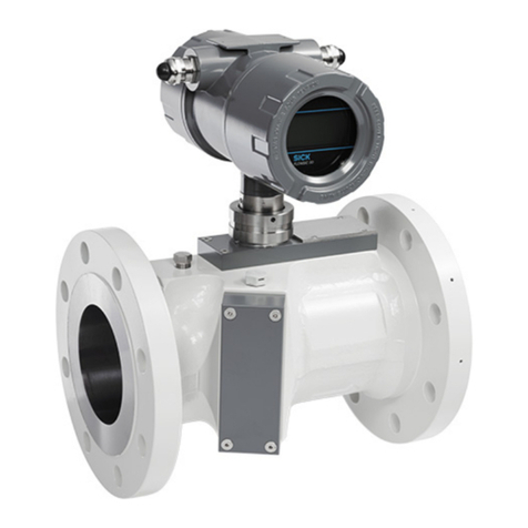
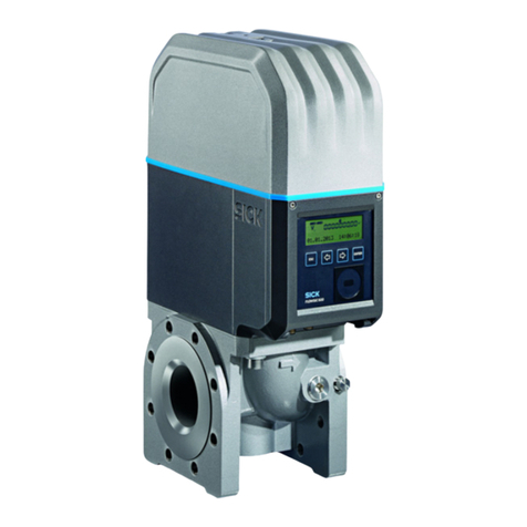
SICK FLOWSIC500 User manual

OPERATING INSTRUCTIONS
Installation
Operation
Maintenance
Title Page
FLOWSIC500
Ultrasonic Gas Flow Meter with
Optional Volume Conversion

2 FLOWSIC500 · Operating Instructions · 8015391 V2.1 · © SICK AG
Document Information
Described Product
Product name: FLOWSIC500
Document ID
Title: Operating Instructions FLOWSIC500
Part No.: 8015391
Version: 2.1
Release: 2014-01
Manufacturer
SICK AG
Erwin-Sick-Str. 1 · D-79183 Waldkirch · Germany
Phone: +49 7641 469-0
Fax: +49 7641 469-1149
E-mail: info.pa@sick.de
Place of Manufacture
SICK Engineering GmbH
Bergener Ring 27 · D-01458 Ottendorf-Okrilla · Germany
Original Documents
The English version 8015391 of this document is an original
document from SICK AG.
SICK AG assumes no liability for the correctness of an
unauthorized translation.
Please contact SICK AG or your local representative in case of
doubt.
Legal Information
Subject to change without notice.
© SICK AG. All rights reserved.
Glossary
AC Alternating Current
Al Aluminium
ATEX ATEX: Atmosphères Explosifs: Abbreviation for
European standards that govern safety in poten-
tially explosive atmospheres
CSA Canadian Standards Association (www.csa.ca)
DC Direct Current
HF High Frequency, e. g., HF pulses (high frequency
pulses)
IEC International Electronical Commission
IECEx IEC system for certification in accordance with stan-
dards for devices for use in potentially explosive
atmospheres
IPxy Ingress Protection: Degree of protection of a device
in accordance with IEC/DIN EN 60529; xspecifies
the protection against contact and impurities, ypro-
tection against moisture.
LF Low Frequency, e. g., LF pulses (low-frequency
pulses)
MDR Manufacturer Data Record
NAMUR Abbreviation for "Normen-Arbeitsgemeinschaft für
Mess- und Regeltechnik in der chemischen Indust-
rie", now "Interessengemeinschaft Automatisier-
ungstechnik der Prozessindustrie" (www.namur.de)
pTZ Volume conversion as a function of the pressure,
the temperature and with consideration of the com-
pression factor
TZ Volume conversion as function of the temperature
and a fixed pressure value and with consideration
of the compression factor

FLOWSIC500 · Operating Instructions · 8015391 V2.1 · © SICK AG 3
Warning Symbols
Warning Levels / Signal Words
DANGER
Risk or hazardous situation which will result in severe personal
injury or death.
WARNING
Risk or hazardous situation which could result in severe personal
injury or death.
CAUTION
Hazard or unsafe practice which could result in personal injury or
property damage.
NOTICE
Hazards which could result in property damage
Information Symbols
IMMEDIATE HAZARD
of severe injuries or death
Hazard (general)
Hazard by electrical voltage
Hazard in potentially explosive atmospheres
Hazard by explosive substances/mixtures
Hazard by unhealthy substances
Hazard by toxic substances
Information on product condition with regard to
protection against explosions (general)
Information on product characteristics related to
European Directive 94/9/EC (ATEX)
Information on product characteristics related to
explosion protection in accordance with the IECEx
scheme.
Important technical information for this product
Important information on electric or electronic
functions
Nice to know
Supplementary information
Link referring to information at another place

Contents
4 FLOWSIC500 · Operating Instructions · 8015391 V2.1 · © SICK AG
1 Important Information . . . . . . . . . . . . . . . . . . . . . . . . . . . . . . . . . . . . . . . . . . . . . . . 7
1.1 Main hazards . . . . . . . . . . . . . . . . . . . . . . . . . . . . . . . . . . . . . . . . . . . . . . . . . . . . . . . . . . . . . . . 8
1.2 About this document . . . . . . . . . . . . . . . . . . . . . . . . . . . . . . . . . . . . . . . . . . . . . . . . . . . . . . . . . 8
1.3 Intended use . . . . . . . . . . . . . . . . . . . . . . . . . . . . . . . . . . . . . . . . . . . . . . . . . . . . . . . . . . . . . . . . 8
1.3.1 Purpose of the device . . . . . . . . . . . . . . . . . . . . . . . . . . . . . . . . . . . . . . . . . . . . . . . . . . . . . . 8
1.3.2 Product identification . . . . . . . . . . . . . . . . . . . . . . . . . . . . . . . . . . . . . . . . . . . . . . . . . . . . . 9
1.3.3 Operation in potentially explosive atmospheres . . . . . . . . . . . . . . . . . . . . . . . . . . . . . 10
1.3.4 Combustible gas . . . . . . . . . . . . . . . . . . . . . . . . . . . . . . . . . . . . . . . . . . . . . . . . . . . . . . . . . 10
1.3.5 Restrictions of use . . . . . . . . . . . . . . . . . . . . . . . . . . . . . . . . . . . . . . . . . . . . . . . . . . . . . . . 10
1.3.6 Cleaning . . . . . . . . . . . . . . . . . . . . . . . . . . . . . . . . . . . . . . . . . . . . . . . . . . . . . . . . . . . . . . . . . 10
1.4 Responsibility of user . . . . . . . . . . . . . . . . . . . . . . . . . . . . . . . . . . . . . . . . . . . . . . . . . . . . . . . 11
1.5 Additional documentation/information . . . . . . . . . . . . . . . . . . . . . . . . . . . . . . . . . . . . . . . . 12
2 Product Description . . . . . . . . . . . . . . . . . . . . . . . . . . . . . . . . . . . . . . . . . . . . . . . . . 13
2.1 Operating principle . . . . . . . . . . . . . . . . . . . . . . . . . . . . . . . . . . . . . . . . . . . . . . . . . . . . . . . . . 14
2.1.1 Gas flow meter . . . . . . . . . . . . . . . . . . . . . . . . . . . . . . . . . . . . . . . . . . . . . . . . . . . . . . . . . . . 14
2.1.2 Volume conversion (optional) . . . . . . . . . . . . . . . . . . . . . . . . . . . . . . . . . . . . . . . . . . . . . . 14
2.2 Device components . . . . . . . . . . . . . . . . . . . . . . . . . . . . . . . . . . . . . . . . . . . . . . . . . . . . . . . . . 15
2.2.1 Meter body . . . . . . . . . . . . . . . . . . . . . . . . . . . . . . . . . . . . . . . . . . . . . . . . . . . . . . . . . . . . . . 15
2.2.2 Meter cartridge . . . . . . . . . . . . . . . . . . . . . . . . . . . . . . . . . . . . . . . . . . . . . . . . . . . . . . . . . . 16
2.3 Meter sizes . . . . . . . . . . . . . . . . . . . . . . . . . . . . . . . . . . . . . . . . . . . . . . . . . . . . . . . . . . . . . . . . 16
2.4 Power supply . . . . . . . . . . . . . . . . . . . . . . . . . . . . . . . . . . . . . . . . . . . . . . . . . . . . . . . . . . . . . . . 16
2.5 Interfaces . . . . . . . . . . . . . . . . . . . . . . . . . . . . . . . . . . . . . . . . . . . . . . . . . . . . . . . . . . . . . . . . . . 17
2.5.1 Pulse and status outputs . . . . . . . . . . . . . . . . . . . . . . . . . . . . . . . . . . . . . . . . . . . . . . . . . . 17
2.5.2 Encoder totalizer . . . . . . . . . . . . . . . . . . . . . . . . . . . . . . . . . . . . . . . . . . . . . . . . . . . . . . . . . 17
2.5.3 Serial data interface . . . . . . . . . . . . . . . . . . . . . . . . . . . . . . . . . . . . . . . . . . . . . . . . . . . . . . 17
2.5.4 Optical data interface . . . . . . . . . . . . . . . . . . . . . . . . . . . . . . . . . . . . . . . . . . . . . . . . . . . . . 17
2.6 Device option: Volume conversion . . . . . . . . . . . . . . . . . . . . . . . . . . . . . . . . . . . . . . . . . . . . 18
2.6.1 Volume conversion . . . . . . . . . . . . . . . . . . . . . . . . . . . . . . . . . . . . . . . . . . . . . . . . . . . . . . . 18
2.6.2 Integrated pressure and temperature transmitters . . . . . . . . . . . . . . . . . . . . . . . . . . 19
2.6.3 External pressure and temperature transmitters . . . . . . . . . . . . . . . . . . . . . . . . . . . . 19
2.7 Totalizers . . . . . . . . . . . . . . . . . . . . . . . . . . . . . . . . . . . . . . . . . . . . . . . . . . . . . . . . . . . . . . . . . . 20
2.7.1 Device status and totalizers used . . . . . . . . . . . . . . . . . . . . . . . . . . . . . . . . . . . . . . . . . . 20
2.7.2 Reverse flow . . . . . . . . . . . . . . . . . . . . . . . . . . . . . . . . . . . . . . . . . . . . . . . . . . . . . . . . . . . . . 20
2.8 Logbooks and Archives . . . . . . . . . . . . . . . . . . . . . . . . . . . . . . . . . . . . . . . . . . . . . . . . . . . . . . 21
2.9 Parameter protection . . . . . . . . . . . . . . . . . . . . . . . . . . . . . . . . . . . . . . . . . . . . . . . . . . . . . . . 22
2.9.1 Parameter locking switch . . . . . . . . . . . . . . . . . . . . . . . . . . . . . . . . . . . . . . . . . . . . . . . . . 22
2.9.2 Metrology logbook . . . . . . . . . . . . . . . . . . . . . . . . . . . . . . . . . . . . . . . . . . . . . . . . . . . . . . . . 22
2.10 Sealing . . . . . . . . . . . . . . . . . . . . . . . . . . . . . . . . . . . . . . . . . . . . . . . . . . . . . . . . . . . . . . . . . . . . 24
3 Installation . . . . . . . . . . . . . . . . . . . . . . . . . . . . . . . . . . . . . . . . . . . . . . . . . . . . . . . . . . . . 27
3.1 Hazards during installation . . . . . . . . . . . . . . . . . . . . . . . . . . . . . . . . . . . . . . . . . . . . . . . . . 28
3.2 General information . . . . . . . . . . . . . . . . . . . . . . . . . . . . . . . . . . . . . . . . . . . . . . . . . . . . . . . . . 28
3.2.1 Delivery . . . . . . . . . . . . . . . . . . . . . . . . . . . . . . . . . . . . . . . . . . . . . . . . . . . . . . . . . . . . . . . . . 28
3.2.2 Transport . . . . . . . . . . . . . . . . . . . . . . . . . . . . . . . . . . . . . . . . . . . . . . . . . . . . . . . . . . . . . . . . 29
3.3 Mechanical installation . . . . . . . . . . . . . . . . . . . . . . . . . . . . . . . . . . . . . . . . . . . . . . . . . . . . . . 29
3.3.1 Preparations . . . . . . . . . . . . . . . . . . . . . . . . . . . . . . . . . . . . . . . . . . . . . . . . . . . . . . . . . . . . . 29
3.3.2 Choosing flanges, gaskets and other components . . . . . . . . . . . . . . . . . . . . . . . . . . . 29
3.3.3 Fitting the FLOWSIC500 in the pipeline . . . . . . . . . . . . . . . . . . . . . . . . . . . . . . . . . . . . . 31
Contents

Contents
FLOWSIC500 · Operating Instructions · 8015391 V2.1 · © SICK AG 5
3.4 Electrical installation . . . . . . . . . . . . . . . . . . . . . . . . . . . . . . . . . . . . . . . . . . . . . . . . . . . . . . . . 33
3.4.1 Requirements for use in potentially explosive atmospheres . . . . . . . . . . . . . . . . . . . 33
3.4.2 Criteria for electrical connection . . . . . . . . . . . . . . . . . . . . . . . . . . . . . . . . . . . . . . . . . . . 35
3.4.3 Opening and closing the electronics cover . . . . . . . . . . . . . . . . . . . . . . . . . . . . . . . . . . 35
3.4.4 Rotating the control unit . . . . . . . . . . . . . . . . . . . . . . . . . . . . . . . . . . . . . . . . . . . . . . . . . . . 36
3.4.5 Electrical connections . . . . . . . . . . . . . . . . . . . . . . . . . . . . . . . . . . . . . . . . . . . . . . . . . . . . . 37
3.4.6 Pin assignment of plug-in connectors . . . . . . . . . . . . . . . . . . . . . . . . . . . . . . . . . . . . . . . 38
3.4.7 Cable specifications . . . . . . . . . . . . . . . . . . . . . . . . . . . . . . . . . . . . . . . . . . . . . . . . . . . . . . 39
3.4.8 Operation with external power supply . . . . . . . . . . . . . . . . . . . . . . . . . . . . . . . . . . . . . . . 40
3.4.9 Operation with batteries . . . . . . . . . . . . . . . . . . . . . . . . . . . . . . . . . . . . . . . . . . . . . . . . . . . 41
3.4.10 Defining the reference potential of the digital switching outputs . . . . . . . . . . . . . . . 42
3.5 Installing the external pressure and temperature transmitters . . . . . . . . . . . . . . . . . . . 43
3.5.1 Fitting the plug-in connector cover . . . . . . . . . . . . . . . . . . . . . . . . . . . . . . . . . . . . . . . . . 43
3.5.2 Installing the pressure transmitter . . . . . . . . . . . . . . . . . . . . . . . . . . . . . . . . . . . . . . . . . 45
3.5.3 Installing the temperature transmitter . . . . . . . . . . . . . . . . . . . . . . . . . . . . . . . . . . . . . . 49
4Start-up. . . . . . . . . . . . . . . . . . . . . . . . . . . . . . . . . . . . . . . . . . . . . . . . . . . . . . . . . . . . . . . . . 51
4.1 Sequence of start-up . . . . . . . . . . . . . . . . . . . . . . . . . . . . . . . . . . . . . . . . . . . . . . . . . . . . . . . . 52
4.1.1 Start-up of gas flow meter . . . . . . . . . . . . . . . . . . . . . . . . . . . . . . . . . . . . . . . . . . . . . . . . . 52
4.1.2 Start-up of gas flow meter with device option volume conversion . . . . . . . . . . . . . . 52
4.2 Setting the date and time . . . . . . . . . . . . . . . . . . . . . . . . . . . . . . . . . . . . . . . . . . . . . . . . . . . . 52
4.3 Configuring volume conversion (device option) . . . . . . . . . . . . . . . . . . . . . . . . . . . . . . . . . 53
4.3.1 Setting fixed values . . . . . . . . . . . . . . . . . . . . . . . . . . . . . . . . . . . . . . . . . . . . . . . . . . . . . . . 53
4.3.2 Checking the configuration . . . . . . . . . . . . . . . . . . . . . . . . . . . . . . . . . . . . . . . . . . . . . . . . 53
4.3.3 Configuring the gas composition . . . . . . . . . . . . . . . . . . . . . . . . . . . . . . . . . . . . . . . . . . . 54
4.4 Checking the device status . . . . . . . . . . . . . . . . . . . . . . . . . . . . . . . . . . . . . . . . . . . . . . . . . . 54
5Operation. . . . . . . . . . . . . . . . . . . . . . . . . . . . . . . . . . . . . . . . . . . . . . . . . . . . . . . . . . . . . . 55
5.1 Control unit . . . . . . . . . . . . . . . . . . . . . . . . . . . . . . . . . . . . . . . . . . . . . . . . . . . . . . . . . . . . . . . . . 56
5.2 Operating using the display . . . . . . . . . . . . . . . . . . . . . . . . . . . . . . . . . . . . . . . . . . . . . . . . . . 56
5.2.1 Display in the symbol bar . . . . . . . . . . . . . . . . . . . . . . . . . . . . . . . . . . . . . . . . . . . . . . . . . . 57
5.2.2 Battery fill level display . . . . . . . . . . . . . . . . . . . . . . . . . . . . . . . . . . . . . . . . . . . . . . . . . . . . 57
5.2.3 Main screen (without device option volume conversion) . . . . . . . . . . . . . . . . . . . . . . 58
5.2.4 Main display (with device option volume conversion) . . . . . . . . . . . . . . . . . . . . . . . . . 60
5.2.5 FLOWSIC500 menu . . . . . . . . . . . . . . . . . . . . . . . . . . . . . . . . . . . . . . . . . . . . . . . . . . . . . . . 64
5.2.6 Changing the user level . . . . . . . . . . . . . . . . . . . . . . . . . . . . . . . . . . . . . . . . . . . . . . . . . . . 69
5.2.7 Setting the language . . . . . . . . . . . . . . . . . . . . . . . . . . . . . . . . . . . . . . . . . . . . . . . . . . . . . . 69
5.2.8 Changing the device mode . . . . . . . . . . . . . . . . . . . . . . . . . . . . . . . . . . . . . . . . . . . . . . . . 69
5.2.9 Changing parameters . . . . . . . . . . . . . . . . . . . . . . . . . . . . . . . . . . . . . . . . . . . . . . . . . . . . . 70
5.2.10 Resetting the error volume . . . . . . . . . . . . . . . . . . . . . . . . . . . . . . . . . . . . . . . . . . . . . . . . 70
5.2.11 Resetting the event summary . . . . . . . . . . . . . . . . . . . . . . . . . . . . . . . . . . . . . . . . . . . . . . 70
5.2.12 Confirming battery replacement . . . . . . . . . . . . . . . . . . . . . . . . . . . . . . . . . . . . . . . . . . . . 71
5.2.13 Testing the display . . . . . . . . . . . . . . . . . . . . . . . . . . . . . . . . . . . . . . . . . . . . . . . . . . . . . . . . 71
5.3 Operating using the optical data interface . . . . . . . . . . . . . . . . . . . . . . . . . . . . . . . . . . . . . 72
5.4 FLOWgate500 operating software . . . . . . . . . . . . . . . . . . . . . . . . . . . . . . . . . . . . . . . . . . . . 72
6 Clearing Malfunctions . . . . . . . . . . . . . . . . . . . . . . . . . . . . . . . . . . . . . . . . . . . . . . . 73
6.1 Contacting Customer Service . . . . . . . . . . . . . . . . . . . . . . . . . . . . . . . . . . . . . . . . . . . . . . . . . 74
6.2 Status messages . . . . . . . . . . . . . . . . . . . . . . . . . . . . . . . . . . . . . . . . . . . . . . . . . . . . . . . . . . . . 74
6.3 Additional messages in the Event logbook . . . . . . . . . . . . . . . . . . . . . . . . . . . . . . . . . . . . . 77

Contents
6 FLOWSIC500 · Operating Instructions · 8015391 V2.1 · © SICK AG
7 Maintenance . . . . . . . . . . . . . . . . . . . . . . . . . . . . . . . . . . . . . . . . . . . . . . . . . . . . . . . . . . 79
7.1 Information on handling lithium batteries . . . . . . . . . . . . . . . . . . . . . . . . . . . . . . . . . . . . . 80
7.1.1 Information on storage and transport . . . . . . . . . . . . . . . . . . . . . . . . . . . . . . . . . . . . . . 80
7.1.2 Disposal information . . . . . . . . . . . . . . . . . . . . . . . . . . . . . . . . . . . . . . . . . . . . . . . . . . . . . 81
7.2 Maintenance when using external power supply . . . . . . . . . . . . . . . . . . . . . . . . . . . . . . . 81
7.2.1 Service life of backup battery . . . . . . . . . . . . . . . . . . . . . . . . . . . . . . . . . . . . . . . . . . . . . . 81
7.2.2 Changing the backup battery . . . . . . . . . . . . . . . . . . . . . . . . . . . . . . . . . . . . . . . . . . . . . . 81
7.3 Maintenance when using battery power supply . . . . . . . . . . . . . . . . . . . . . . . . . . . . . . . . 82
7.3.1 Service life of battery packs . . . . . . . . . . . . . . . . . . . . . . . . . . . . . . . . . . . . . . . . . . . . . . . 82
7.3.2 Changing the battery packs . . . . . . . . . . . . . . . . . . . . . . . . . . . . . . . . . . . . . . . . . . . . . . . 82
7.4 Function check of a pressure or temperature transmitter . . . . . . . . . . . . . . . . . . . . . . . 83
7.5 Exchanging an external pressure or temperature transmitter . . . . . . . . . . . . . . . . . . . . 84
7.5.1 Exchanging the pressure transmitter . . . . . . . . . . . . . . . . . . . . . . . . . . . . . . . . . . . . . . . 84
7.5.2 Exchanging the temperature transmitter . . . . . . . . . . . . . . . . . . . . . . . . . . . . . . . . . . . . 84
8 Accessories and Spare Parts . . . . . . . . . . . . . . . . . . . . . . . . . . . . . . . . . . . . . . 85
8.1 Accessories . . . . . . . . . . . . . . . . . . . . . . . . . . . . . . . . . . . . . . . . . . . . . . . . . . . . . . . . . . . . . . . . 86
8.1.1 Gas flow meter accessories . . . . . . . . . . . . . . . . . . . . . . . . . . . . . . . . . . . . . . . . . . . . . . . 86
8.1.2 Volume conversion (device option) accessories . . . . . . . . . . . . . . . . . . . . . . . . . . . . . 87
8.2 Spare parts . . . . . . . . . . . . . . . . . . . . . . . . . . . . . . . . . . . . . . . . . . . . . . . . . . . . . . . . . . . . . . . . 87
8.2.1 Gas flow meter spare parts . . . . . . . . . . . . . . . . . . . . . . . . . . . . . . . . . . . . . . . . . . . . . . . . 87
8.2.2 Volume conversion (device option) spare parts . . . . . . . . . . . . . . . . . . . . . . . . . . . . . . 87
9 Annex . . . . . . . . . . . . . . . . . . . . . . . . . . . . . . . . . . . . . . . . . . . . . . . . . . . . . . . . . . . . . . . . . . . 89
9.1 Conformities and Technical Data . . . . . . . . . . . . . . . . . . . . . . . . . . . . . . . . . . . . . . . . . . . . . 90
9.1.1 CE certificate . . . . . . . . . . . . . . . . . . . . . . . . . . . . . . . . . . . . . . . . . . . . . . . . . . . . . . . . . . . . 90
9.1.2 Standards compatibility . . . . . . . . . . . . . . . . . . . . . . . . . . . . . . . . . . . . . . . . . . . . . . . . . . . 90
9.1.3 Technical Data . . . . . . . . . . . . . . . . . . . . . . . . . . . . . . . . . . . . . . . . . . . . . . . . . . . . . . . . . . . 91
9.1.4 Flow rates . . . . . . . . . . . . . . . . . . . . . . . . . . . . . . . . . . . . . . . . . . . . . . . . . . . . . . . . . . . . . . . 93
9.1.5 Overload protection . . . . . . . . . . . . . . . . . . . . . . . . . . . . . . . . . . . . . . . . . . . . . . . . . . . . . . 93
9.2 Type plates . . . . . . . . . . . . . . . . . . . . . . . . . . . . . . . . . . . . . . . . . . . . . . . . . . . . . . . . . . . . . . . . 94
9.2.1 Metrology and electronics type plates . . . . . . . . . . . . . . . . . . . . . . . . . . . . . . . . . . . . . . 94
9.2.2 Meter body type plate (example) . . . . . . . . . . . . . . . . . . . . . . . . . . . . . . . . . . . . . . . . . . . 95
9.3 Dimensional drawings . . . . . . . . . . . . . . . . . . . . . . . . . . . . . . . . . . . . . . . . . . . . . . . . . . . . . . . 96
9.4 Internal terminal assignment . . . . . . . . . . . . . . . . . . . . . . . . . . . . . . . . . . . . . . . . . . . . . . . . 97
9.5 Installation examples . . . . . . . . . . . . . . . . . . . . . . . . . . . . . . . . . . . . . . . . . . . . . . . . . . . . . . . 98
9.6 Connection diagrams for operation of the FLOWSIC500 in accordance with CSA . 101
9.7 Connection diagrams for operation of the FLOWSIC500 in accordance with
ATEX/IECEx . . . . . . . . . . . . . . . . . . . . . . . . . . . . . . . . . . . . . . . . . . . . . . . . . . . . . . . . . . . . . . . 107

Important Information
FLOWSIC500 · Operating Instructions · 8015391 V2.1 · © SICK AG 7
Subject to change without notice
FLOWSIC500
1Important Information
Main hazards
About this document
Intended use
Responsibility of user

8 FLOWSIC500 · Operating Instructions · 8015391 V2.1 · © SICK AG
Important Information
Subject to change without notice
1.1 Main hazards
1.2 About this document
This Manual describes:
– Device components
– Installation
– Operation of the FLOWSIC500.
It contains the main safety information for safe operation of the FLOWSIC500.
1.3 Intended use
1.3.1 Purpose of the device
The FLOWSIC500 serves for measuring the gas volume, volume flow rate and gas velocity
of natural gas in pipelines.
The FLOWSIC500 with optional volume conversion serves for measuring the gas volume
and converting the gas volume measured to base conditions as well as registering data on
meter readings, maximums and other data.
DANGER: Risk of explosion when the cartridge is damaged
Natural gas flows through the upper part ("meter cartridge") of the
FLOWSIC500 with line pressure. Natural gas can escape when the cartridge is
damaged which creates a risk of explosion.
▸
Prevent any possible damage to the meter cartridge. When necessary, fit
protection devices.
▸
If the meter cartridge is damaged: Stop natural gas feed immediately and
purge the FLOWSIC500 with inert gas.
WARNING: Hazards through leaks
Operation in leaky condition is not allowed and potentially dangerous.
▸
Regularly check leak tightness of equipment.

Important Information
FLOWSIC500 · Operating Instructions · 8015391 V2.1 · © SICK AG 9
Subject to change without notice
1.3.2 Product identification
The type plates for metrological and electrical parameters are located on the meter
cartridge.
The type plate for the Pressure Equipment Directive is located on the meter body.
Fig. 1 Location of type plates
●Example for metrology type plate p. 94, §9.2.1.1.
●Example for electronics type plate p. 95, §9.2.1.2
●Example for meter body type plate p. 95, §9.2.2.
Product name: FLOWSIC500
Manufacturer:
SICK AG
Erwin-Sick-Str. 1
79183 Waldkirch
Germany
Place of manufacture:
SICK Engineering GmbH
Bergener Ring 27
01458 Ottendorf-Okrilla
Germany
2
1
3
1 Type plate, metrological parameters (metrology)
2 Type plate, electrical parameters (electronics)
3 Type plate, meter body

10 FLOWSIC500 · Operating Instructions · 8015391 V2.1 · © SICK AG
Important Information
Subject to change without notice
1.3.3 Operation in potentially explosive atmospheres
1.3.4 Combustible gas
▸
The FLOWSIC500 is suitable for measuring combustible and occasionally ignitable
gases corresponding to zones 1 and 2.
1.3.5 Restrictions of use
▸
Refer to the type plate for the configuration of your FLOWSIC500.
▸
Check the FLOWSIC500 is suitably equipped for your application (e.g., gas conditions).
1.3.6 Cleaning
The FLOWSIC500 is suitable for use in potentially explosive atmospheres:
ATEX: II 2G Ex ia [ia] IIB T4 Gb
IECEx: Ex ia [ia] IIB T4 Gb
US/C: Class I Division 1, Groups C, D T4, Ex/AEx ia IIB T4 Ga
Further information on potentially explosive atmospheres p. 33, §3.4.1.
WARNING: Hazard through material fatigue
The FLOWSIC500 has been designed for use under mainly static loads.
▸
Maximum allowed gradient of static pressure: 3 bar/s (45psi/sec)
The number of complete pressure application and release processes should
be kept low during operation.
▸
Replace the device when 500 cycles have been reached.
NOTICE:
The FLOWSIC500 is designed for measuring clean and dry natural gas.
▸
The operator should install a suitable filter or cone screen ahead of the gas
flow meter when the gas is contaminated.
NOTICE:
●The FLOWSIC500 is suitable for use in pressurized lines within the
parameters specified in the device. The device complies with Pressure
Equipment Directive 97/23/EC.
●It is the user's responsibility to ensure the maximum values specified for
pressure and temperature on the type plate are not exceeded during
operation.
NOTICE: Cleaning information
▸
Only clean the FLOWSIC500 with a damp cloth.
▸
Do not use solvents for cleaning.
▸
Only use materials for cleaning which do not damage the surface of the
FLOWSIC500.

Important Information
FLOWSIC500 · Operating Instructions · 8015391 V2.1 · © SICK AG 11
Subject to change without notice
1.4 Responsibility of user
▸
Only put the FLOWSIC500 into operation after reading the Operating Instructions.
▸
Observe all safety information.
▸
If anything is not clear: Please contact the SICK Customer Service.
Designated users
The FLOWSIC500 may only be operated by skilled technicians who, based on their
technical training and knowledge as well as knowledge of the relevant regulations, can
assess the tasks given and recognize the hazards involved.
Correct use
▸
Only use the FLOWSIC500 as described in these Operating Instructions (p. 8, §1.3.1).
The manufacturer bears no responsibility for any other use.
▸
Do not carry out any work or repairs on the FLOWSIC500 not described in this manual.
▸
Do not remove, add or change any components in or on the FLOWSIC500 unless such
changes are officially allowed and specified by the manufacturer.
Otherwise
– Any warranty by the manufacturer becomes void
– The FLOWSIC500 can become dangerous
– The approval for use in potentially explosive atmospheres is no longer valid
– The approval fur use in lines pressurized above 0.5 bar (7.25 psi) bar is no longer
valid.
Special local conditions
▸
Follow all local laws, regulations and company-internal operating directives applicable
at the installation location.
Retention of documents
These Operating Instructions must be
▸
Kept available for reference
▸
Passed on to new owners.
NOTICE:
Skilled persons are persons in accordance with DIN VDE 0105 or IEC 364, or
directly comparable standards.
These persons must have exact knowledge on hazards arising from operation,
e.g. through hot, toxic, explosive gases or gases under pressure, gas-liquid
mixtures or other media as well as adequate knowledge of the measuring
system gained through training.
WARNING: Danger identification on device
The following symbol draws attention to important dangers directly on the
device:
▸
Consult the Operating Instructions in all cases where the symbol is
attached to the device or shown on the display.

12 FLOWSIC500 · Operating Instructions · 8015391 V2.1 · © SICK AG
Important Information
Subject to change without notice
1.5 Additional documentation/information
Some parameter settings, components and characteristics depend on the individual
device configuration. This individual device configuration is described in the device
documentation delivered with the device.
●Certificate of conformity/EX certificates (depending on configuration)
●Material certificate
●Inspection certificate
– Device configuration sheet
– Encoder test protocol (if configured)
– Low-pressure calibration test protocol (if ordered)
– Labels according to Pressure Equipment Directive 97/23/EC, Annex 1 Part 3.3
●Printout of the Data Book
●Product CD with:
– Operating Instructions
– Operating program FLOWgate500
– FLOWgate500 Software Manual
–Keycode
– Instructions for Kamstrup test valve BDA04

Product Description
FLOWSIC500 · Operating Instructions · 8015391 V2.1 · © SICK AG 13
Subject to change without notice
FLOWSIC500
2Product Description
Operating principle
Device components
Meter sizes
Power supply
Interfaces
Device option: Volume conversion
Totalizers
Logbooks and Archives
Parameter protection
Sealing

14 FLOWSIC500 · Operating Instructions · 8015391 V2.1 · © SICK AG
Product Description
Subject to change without notice
2.1 Operating principle
2.1.1 Gas flow meter
The FLOWSIC500 works according to the principle of ultrasonic transit time difference
measurement.
Fig. 2 Functional principle
Measured signal transit times tAB and tBA are defined by the current sound and gas
velocity.
Gas velocity v is determined from the difference between the signal transit times. There-
fore changes in the sound velocity caused by pressure or temperature fluctuations do not
affect the calculated gas velocity with this measurement method.
The FLOWSIC500 calculates the volume flow rate internally from the gas velocity and the
pipeline diameter.
2.1.2 Volume conversion (optional)
The integrated volume conversion converts the measured gas volume from measurement
conditions to base conditions.
Calculation according to EN 12405:
The measurement conditions are either determined with pressure and temperature trans-
mitters or entered as fixed value.
v = Gas velocity in ft/s
L = Measuring path in ft
= Angle of inclination in °
tAB = Sound transit time
in flow direction
tBA = Sound transit time
against flow direction
DI= Pipe inner diameter
Q=Volumeflow
The following short forms are used in this document for better readability:
●Volume at base conditions = base volume
●Volume at measurement conditions = measurement volume
Q
4
---DI
2L
2cos
----------------tBA tAB
–
tAB tBA
----------------------
=
VbCV
m
=Vb= Volume at base conditions
C = Conversion factor
Vm= Volume at measurement conditions
p = Gas pressure at measurement conditions
pb= Pressure at base conditions
T = Gas temperature at measurement conditions
Tb= Temperature at base conditions
Zb= Compression factor at base conditions
Z = Compression factor at measurement conditions
Cp
pb
----- Tb
T
------Zb
Z
------
=

Product Description
FLOWSIC500 · Operating Instructions · 8015391 V2.1 · © SICK AG 15
Subject to change without notice
2.2 Device components
The FLOWSIC500 comprises:
●Meter body
●Meter cartridge.
Fig. 3 FLOWSIC500 components
2.2.1 Meter body
A meter body serves to install the FLOWSIC500 in the pipeline. The meter body is available
in various flange standards and fitting lengths to connect the meter cartridge to the system
pipeline.
Depending on the version, the meter body is designed for assembly on line flanges PN16 in
accordance with DIN EN1092-1, CL150 in accordance with ASME B16.5, or 1.6MPa in
accordance with GOST 12815-80.
Meter cartridge
Meter body
Fitting lengths available: p. 96, §9.3.

16 FLOWSIC500 · Operating Instructions · 8015391 V2.1 · © SICK AG
Product Description
Subject to change without notice
2.2.2 Meter cartridge
The meter cartridge is fitted on the meter body.
The complete gas flow is channeled through the cartridge for measurement.
An internal flow conditioner rectifies the gas flow so that flow profile disturbances caused
by pipe bends in the inlet or outlet sections or components projecting into the pipe (e.g., a
thermowell) have no influence on measuring results.
The meter cartridge can be exchanged without taking the meter body out of the pipeline.
The meter cartridge contains:
●Control unit
●Optical and electrical interfaces
●Measuring cell with ultrasonic transducers
●Electronics.
The product variant with volume conversion and integrated pressure and temperature
transmitters also has the calibrated pressure transmitter and calibrated temperature
transmitter fitted in the meter cartridge.
2.3 Meter sizes
Available meter sizes p. 96, §9.3.
2.4 Power supply
The FLOWSIC500 is available with two configurations:
●For operation with external intrinsically safe power supply with backup battery in the
meter cartridge (backup duration: Approx. 3 months).
●Self-sufficient power configuration: 2 internal longlife battery packs (typical service life:
At least 5 years).
The second battery pack is activated automatically when the first pack is empty and a
message displayed (p. 56, §5.2).

Product Description
FLOWSIC500 · Operating Instructions · 8015391 V2.1 · © SICK AG 17
Subject to change without notice
2.5 Interfaces
The FLOWSIC500 supports various digital and serial interfaces.
The configuration of the interfaces as delivered is described in the delivery documents pro-
vided with the respective device.
2.5.1 Pulse and status outputs
FLOWSIC500 has 4 digital switching outputs. Digital switching output DO_0 is designed
electrically isolated according to EN 60947-5-6. Pulses (NAMUR) or a status can be output
via this digital switching output.
An external voltage supply is recommended when DO_0 is used as NAMUR pulse output.
Digital switching outputs DO_1 - DO_3 are transistor outputs not electrically isolated
(emulation of a Reed contact). They can be configured as status or pulse outputs.
The digital switching outputs are updated synchronously once per second. They provide
information on the current volume flow under measurement conditions with flow propor-
tional pulses.
The maximum pulse frequency can be set to 10 Hz or 2 kHz at 120% Qmax. Measurement
validity and the result of the self-diagnosis function of the device are output via the status
outputs.
2.5.2 Encoder totalizer
Alternatively, NAMUR switching output DO_0 can be configured so that the reading of
totalizer Vm, the meter status and a meter identification are output via asynchronous serial
communication. This allows the connection of volume convertors with a suitable input for
encoder totalizers.
2.5.3 Serial data interface
The serial interface is designed as externally powered RS485 and requires an external
intrinsically safe power supply for operation. The RS485 interface has no internal line
termination.
2.5.4 Optical data interface
An optical interface according to IEC 62056-21 with serial bit, asynchronous data trans-
mission is located on the front of the FLOWSIC500.
The interface can be used to read out data and parameter settings and to configure the
FLOWSIC500.
Table 1 Interface configurations
Config. 1 (LF) Config. 2 (HF) Config 3 (Encoder) Config. 4 (RS485)
DO_0 - HF pulses Encoder RS485
DO_1 Diagnosis warning Measured value
validity
Measured value
validity
Measured value
validity
DO_2 LF pulses - - -
DO_3 Measured value
validity
---
●Information on explosion-technical characteristics and rated voltage
p. 33, §3.4.
●Details on standard interface configurations available p. 38, §3.4.6.

18 FLOWSIC500 · Operating Instructions · 8015391 V2.1 · © SICK AG
Product Description
Subject to change without notice
2.6 Device option: Volume conversion
2.6.1 Volume conversion
The FLOWSIC500 gas flow meter with volume conversion captures the gas volume under
measurement conditions and converts it to a volume under base conditions.
Gas volume conversion can run selectively (set at the factory) as PTZ or TZ volume conver-
sion: The configuration as temperature volume conversion uses the default value for
measurement pressure for calculations.
Measurement conditions are recorded with the pressure and temperature transmitters or
entered as fixed values.
By default, measured values recording and subsequent conversion to the volume under
base conditions are performed every 30 seconds. The update interval can be adjusted
p. 66, "Calculation".
Depending on the configuration, the compressibility factor (K-factor) is determined with
one of the following calculation methods or can be entered as a fixed value.
●SGERG88,
●AGA 8 Gross method 1
●AGA 8 Gross method 2
●AGA NX-19
●AGA NX-19 mod.
●Fixed value
The FLOWSIC500 checks the permissible entry limits of the parameters for the selected
calculation method. If one of the entry values is outside the limit values, the FLOWSIC500
switches to malfunction state and uses the fixed value of the compressibility factor for
calculation of the basis volume.
An absolute pressure transmitter EDT 23 (optional: relative pressure transmitter EDT 23)
and a temperature transmitter EDT 34 measure current measurement conditions and
transfer the transmitter type, measured value as well as the transmitter status via a digital
interface.
The FLOWSIC500 reads the valid measuring range automatically and, periodically, the
current status and measured value.
A transmitter is only activated for measurement when the configured serial number
matches the serial number transferred for the transmitter.
If no transmitter is detected or a transmitter is not functioning correctly, the
FLOWSIC500 automatically uses the stored default value (= fixed value) of the state
variable.
In this case, the FLOWSIC500 switches to malfunction state and, using the default value,
stores the volume under base conditions calculated for pressure or temperature in the
error volume counter.
If not specified otherwise, the FLOWSIC500 is supplied with the following standard
settings:
Table 2 Standard settings
Unit system SI Imperial
T unit °C ° F
P unit bar psi
Symbols according to EN 12405 API
Calculation method SGERG88 AGA 8 Gross method 1
Reference conditions for den-
sity and heating value
(T1/T2/p2)
25 °C/0 °C/1.01325 bar (a)
(T1/T2/p2)
60 °F/60 °F/14.7300 psi (a)
Standard pressure 1.01325 bar (a) 14.7300 psi (a)
Standard temperature 0 °C 60 °F

Product Description
FLOWSIC500 · Operating Instructions · 8015391 V2.1 · © SICK AG 19
Subject to change without notice
2.6.2 Integrated pressure and temperature transmitters
The FLOWSIC500 with volume conversion and integrated pressure and temperature trans-
mitters does not have any external components. The internal pressure and temperature
transmitters are already fitted and calibrated at the factory. The measuring ports are
located in the meter cartridge.
This means the FLOWSIC500 does not require any additional installation of transmitters to
determine the measurement conditions and is immediately ready for operation after
volume conversion has been configured.
2.6.3 External pressure and temperature transmitters
The FLOWSIC500 with volume conversion and external transmitters is used at measuring
ports where a test/calibration of the pressure or temperature transmitter in the system
may be required.
It is recommended to install a three-way test valve that separates the pressure transmitter
from the measurement pressure and provides a test connection to test the pressure trans-
mitter.
Fig. 4 shows a FLOWSIC500 with external transmitters and Kamstrup test valve BDA04
for gas temperatures to -25°C.
Fig. 4 FLOWSIC500 with external transmitters and Kamstrup test valve BDA04
A three-way test valve (Fig. 5) that is fitted next to the FLOWSIC500 is used for gas
temperatures to -40°C.
1 Pressure transmitter
2 Kamstrup test valve BDA04
3 Temperature transmitter
2
3
1

20 FLOWSIC500 · Operating Instructions · 8015391 V2.1 · © SICK AG
Product Description
Subject to change without notice
Fig. 5 Three-way test valve with p transmitter and Minimess coupling
2.7 Totalizers
2.7.1 Device status and totalizers used
Various volume totalizers are fitted on the FLOWSIC500 depending on the configuration.
Meter V is used in the configuration as gas flow meter. If the gas flow meter has a malfunc-
tion, the measured volume is also recorded in the error volume counter errV.
A gas flow meter Vm, a base volume meter Vb and a total volume meter Vbtot are used in
the configuration as gas flow meter with integrated volume conversion (device option). If
malfunctions occur, the measured values are not recorded in the base volume meter Vb,
but the converted volume is recorded in the error volume meter errVb.
Authorized users (user level "Authorized user") can reset the error volume counters p. 70,
§5.2.10.
2.7.2 Reverse flow
The FLOWSIC500 is designed as unidirectional type and has a configurable zero-flow cutoff
which is factory set to a value of 1 m3(35 ft3) as default.
The totalizers are stopped during reverse flow and this volume is counted in a separate
buffer totalizer. When normal operation resumes, the buffer totalizer is first computed with
the flow.
1FLOWSIC500connection
2 Three-way test valve
3 Test connection (Minimess coupling)
4 Pressure transmitter
1
2
3
4
Table 3 Device status and totalizers used
Status Totalizer
VerrV
Operation
Malfunction
Table 4 Device status and totalizers used (with device option volume conversion)
Status Totalizer
Vb errVb Vbtot Vm errVm
Operation
Malfunction
Other manuals for FLOWSIC500
3
Table of contents
Other SICK Measuring Instrument manuals

SICK
SICK GTE2 Flat G 2F- 14 Series User manual

SICK
SICK DL100 Pro User manual

SICK
SICK nanoScan3 I/O User manual

SICK
SICK FLOWSIC100 Flare User manual

SICK
SICK WebChecker MLG-2 User manual

SICK
SICK RFH620 User manual

SICK
SICK GM700 User manual

SICK
SICK DL100-SSI User manual

SICK
SICK FLOWSIC600-XT User manual

SICK
SICK Lector63x Flex C-mount User manual

SICK
SICK VMS410 User manual

SICK
SICK VMS4100 User manual

SICK
SICK WTB4S-3 User manual

SICK
SICK Master Data Analyzer User manual

SICK
SICK FFU User manual

SICK
SICK FWE200DH User manual

SICK
SICK T-EASIC FTS User manual

SICK
SICK PowerCEMS100 User manual

SICK
SICK WebChecker MLG-2 User manual

SICK
SICK FLOWSIC500 User manual