2007- 08-24 SENSICK 3
Second output or input
In addition to the switching output Q1, the second
connection can be assigned as the second swit-
ching output Q2, alarm output, external Teach-in
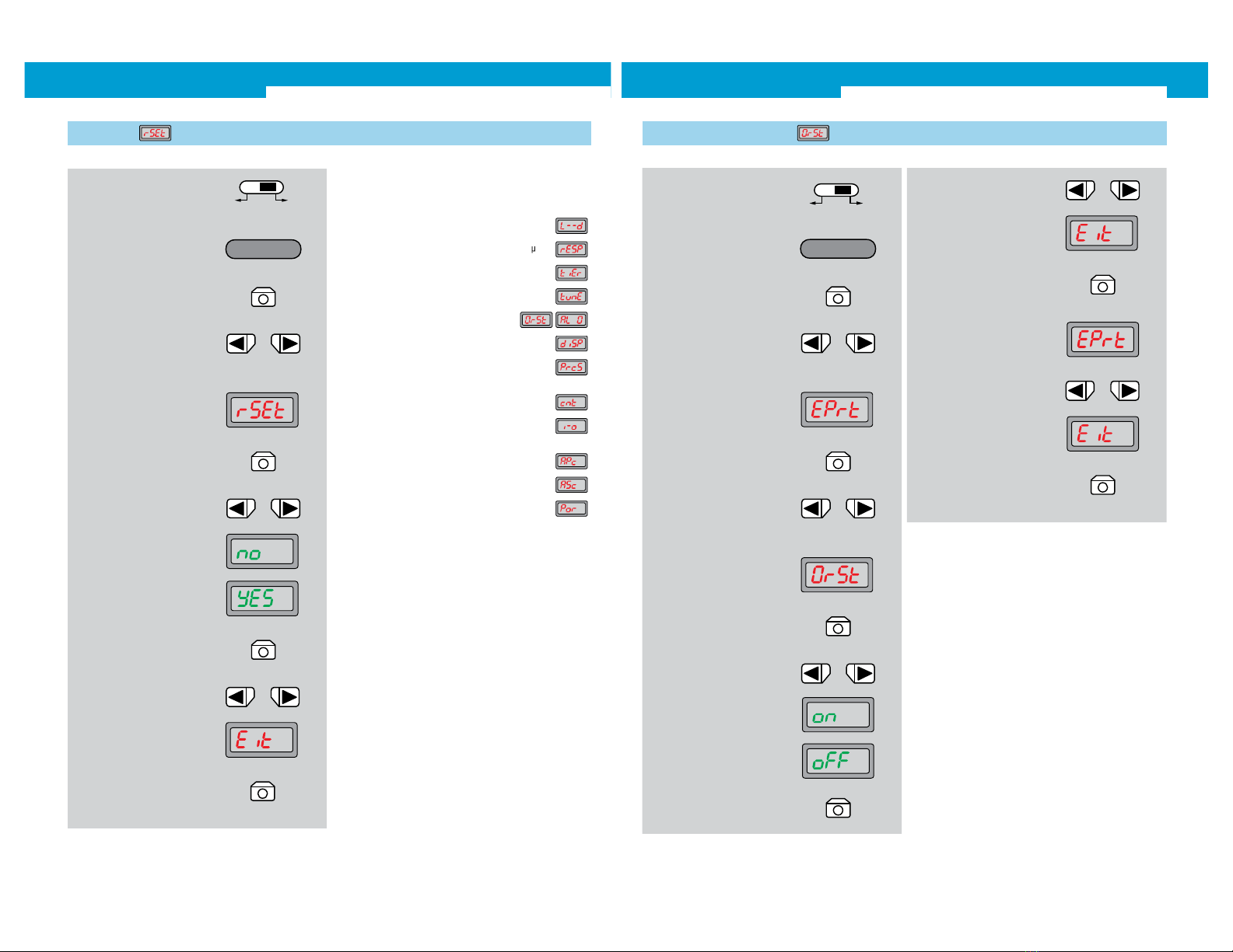
input or for resetting the counter.
Version with analogue and switching output
Suitable for many different applications, such as
position control.
From monitoring to power control.
Monitoring simplifies many things, and technical highlights
provide many options, always enabling easy commission-
ing and permanently reliable operation.
2 x 4 - DI G I T N U M E RI C D I S P L AY
Dual 7-segment display for simultaneously showing nomi-
nal/actual values and for interactive operator guidance.
A S C
A U T O M A T I C S E N S I T I V I T Y C O N T R O L
For instance, automatically adapting the switching
threshold to compensate for contamination when
detecting transparent objects.
A U T O M A T I C S E N S I T I V I T Y C O R R E C T I O N
Adaptation of the measuring range to the service signal,
for optimum resolution.
Especially for detecting:
objects at longer distances/objects with low reflectance
(spreading the measuring range),
close objects/objects with high reflectance
(preventing saturation).
Compensation of the natural attenuation of the
sender LED constant sender power levels for long,
maintenance-free operation.
A P C A U T O M A TI C P O W E R C O N T R O L
The power of the sender LED can be adjusted in three
stages: saturation, e. g. in case of heavily reflecting
objects, is prevented.
A D J U S T I N G T H E L I G H T I N T E N S I T Y
O F T H E S E N D E R L E D
WLL190T-2 Photoelectric switches for fibre-optic cables
4 SENSICK
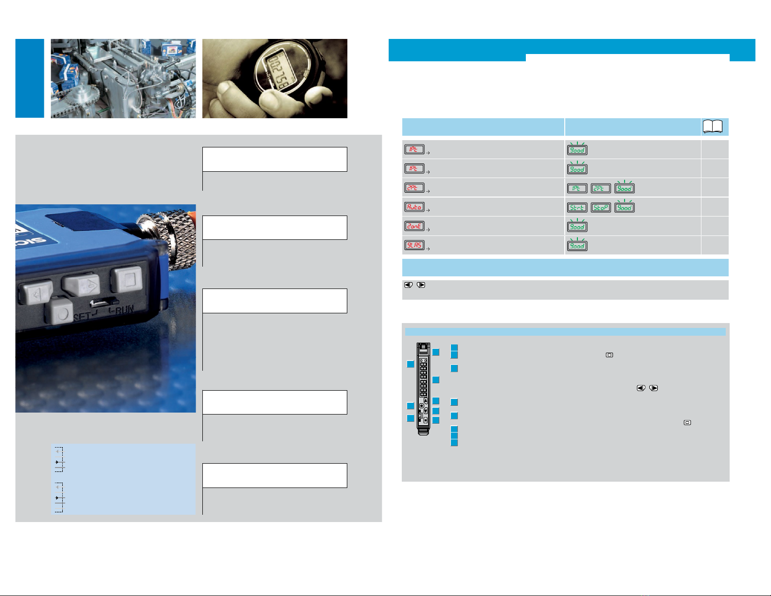
Teach-in Adjustment options
Max. Teach-in
for setting the maximum sensitivity
1.1
Page 6
1-point Teach-in
to quickly learn the switching point
1.2
Page 7
2-point Teach-in
to safely learn the switching point , ,
1.3
Page 8
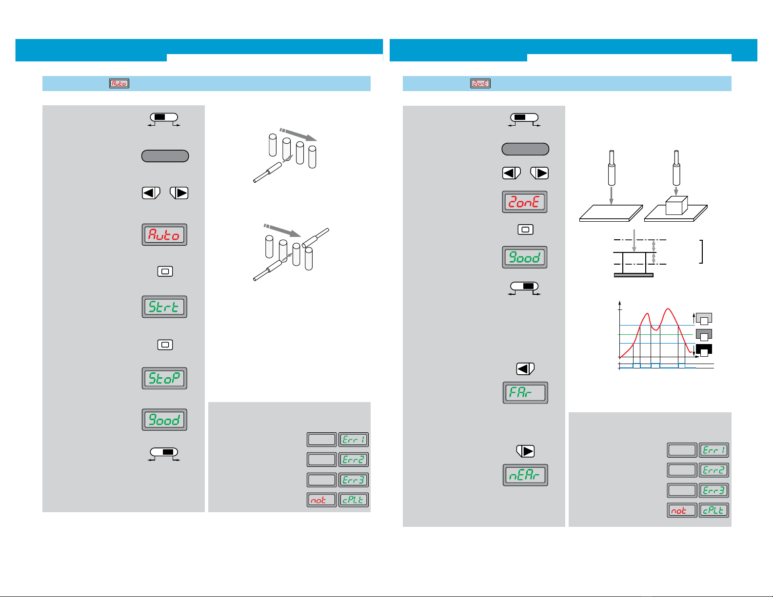
Auto Teach-in
for Teach-in without stopping the production process , ,
1.4
Page 9
Zone Teach-in
for learning an upper and lower switching threshold
1.5
Page 10
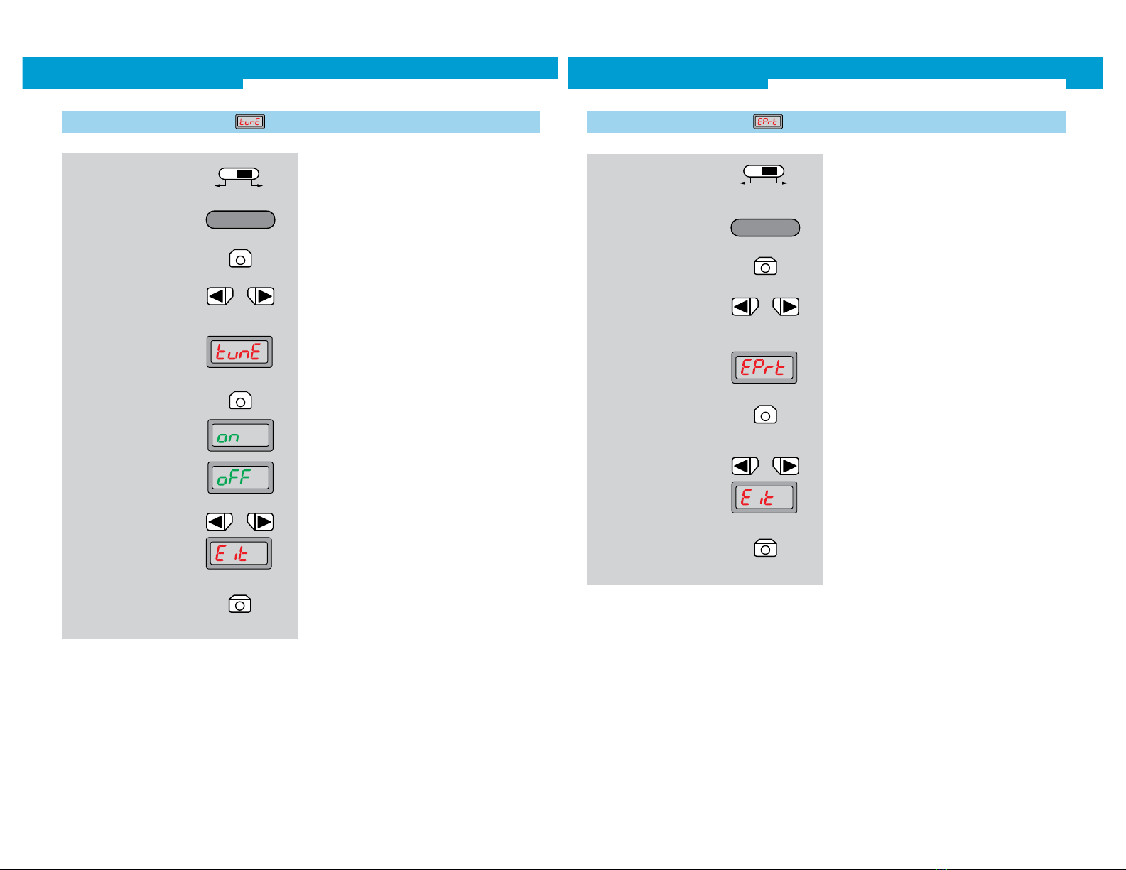
Transparent Teach-in
transparent objects such as bottles and films
1.6
Page 11
For standard applications: Teach-in and the commissioning is complete.
The automatic learning with Teach-in is always the first step. The six different Teach-in versions can
be quickly and easily selected. For standard applications, the settings automatically selected by
the sensor are sufficient for stable operation.
Manual adaptation of the switching threshold
Manual, step-by-step modification of the switching
thresholds by operating the arrow keys. After a few seconds,
the display automatically jumps to the operating mode.
Within the zone Teach-in, first, the arrow keys are used to select the
close or far range, and then the respective switching threshold is
adjusted via the arrow keys.
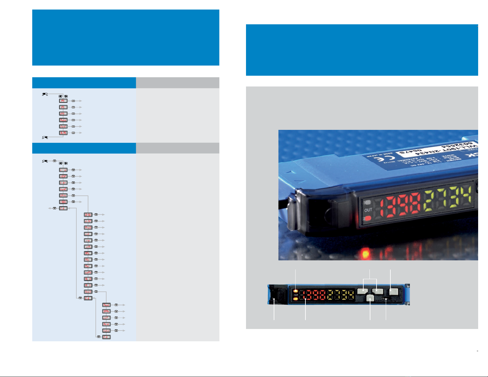
Locking, fibre-optic cable
2x display LED orange: lights
when the switching output is active
Display, numeric: 4-digit
green: switching threshold, operating
mode,
red: current reception value, Teach-in/
function parameter
Arrow key < (manual switching threshold:
higher resp. next function parameter)
Step key > (manual switching threshold:
lower or previous parameter)
Teach-in key
Mode/Enter key (programming key)
Selector switch, operating mode:
SET Teach-in switching thresholds
active
RUN sensor mode and selection of
function parameter
Function keys of the evaluation unit Further functions
Quick jump back from configuration mode to operating mode.
By pressing the -key for at least 2 seconds, the display
jumps from any position in the configuration menu to the
operational status indicator.
Keylocks
Simultaneously pressing the arrow keys for at least
2 seconds in the RUN mode, locks or unlocks the keys (dis-
play Loc/unloc).
Channel switching (ch1, ch2)
Changing the switching channel by pressing the
-key in
RUN mode. Active channel ch1 or ch2 is shown in the dis-
play. Active channel can be taught, and measurement value is
shown in the display.