3
SE 80/185 T - SE 100/185 T - SE 130/250T 1.0.1- 2008
Motor: Spesialutviklet reversibel DC-motor.
Girhus: Sjøvannsbestandig bronsje. Kulelagre på pro-
pellaksel. Kule og glidelager komb. på drivaksel.
Motorbraket: Sjøvannsbestandig aluminium.
Galvanisk isolert fra motor
Tunnel: Kryssvevet glassber.
Aluminium og ståltunnel på forespørsel.
Propell: 5-llads skew "Q"-propell i kompositmateriale.
Batterier: Minimum anbefalt batteri størrelse.
(Kaldstart kapasitet etter DIN/SAE std.)
SE 80/185T 12V : 550 CCA DIN/1045 CCA SAE
SE 80/185T 24V : 300 CCA DIN/570 CCA SAE
SE 100/185T 12V : 750 CCA DIN/1425 CCA SAE
SE 100/185T 24V : 400 CCA DIN/760 CCA SAE
SE 130/250T 12V : 750 CCA DIN/1425 CCA SAE
SE 130/250T 24V : 400 CCA DIN/760 CCA SAE
Drift tid: S2 = 3 min. Eller gjennomsnittlig 7-10% innen
en begrenset tidsperiode.
Sikkerhet: Elektronisk tidsforsinkelse forhindrer motorskade
ved rask retningsendring.
Motoren stanser automatisk ved overopphetning
(slår seg automatisk på etter nedkjøling).
Brytepinne mellom drivaksel og motor beskytter
gir hvis propell blir blokkert.
Om orginalt Side-Power panel blir brukt så vil
dette slås av automatisk etter 6 minutter etter
siste gang trøsteren ble brukt.
Integrerte microprossessor føler hele tiden på
releet, reduserer slitasje og risk for ”heng” på
relé. Trøsteren vil stoppe automatisk etter 3
minutter om det oppstår ”heng” på relé, eller
om trøsteren går kontinuerlig i 3 minutter.
Tekniske spesikasjoner
N
Motor: Custom made reversible DC-motor.
Gearhouse: Seawater resistant bronze. Ballbearing at
propellershaft and combination of ballbearing
and slide bearing at driveshaft.
Motor bracket: Seawaterresistant aluminium,
galvanicly insulated from motor
Tunnel: Cross spun with rowing G.R.P tunnel
Steel & aluminum tunnels available at request.
Propeller: 5 blade skew "Q"-propeller,
breglass reinforced composite.
Batteries:
Minimum recommended battery capacity
(cold crank capacity by DIN/SAE standard)
SE 80/185T 12V : 550 CCA DIN/1045 CCA SAE
SE 80/185T 24V : 300 CCA DIN/570 CCA SAE
SE 100/185T 12V : 750 CCA DIN/1425 CCA SAE
SE 100/185T 24V : 400 CCA DIN/760 CCA SAE
SE 130/250T 12V : 750 CCA DIN/1425 CCA SAE
SE 130/250T 24V : 400 CCA DIN/760 CCA SAE
Max. use: S2 = 3 min. or appr. 7-10% within a limited time
frame.
Safety
:
Electronic time-lapse device protects against
sudden change of drive direction. Electric thermal
cut-off switch in electromotor protects against
over heating (auto reset when electro motor cools
down).
Flexible coupling between electro-motor and
driveshaft protects electromotor and gearsystem
if propeller gets jammed.
If original Sidepower panel is used, the panel
shuts off automatically 6 minutes after last use.
Integrated microprocessor monitors solenoids,
reducing wear and risk of solenoid lock-in. Auto-
stop of thruster in case of accidental solenoid
lock-in or if run signal is continous for more than
3 minutes
Technical specications
GB
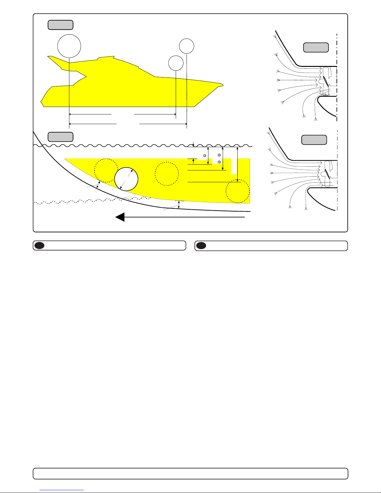
SE80/185T SE100/185T SE130/250T
Thrust [lbs] 176 212 284
A [in] 7,28 7,28 9,84
B [in] 13,9 15,3 15,7
Cmin. [in] 7,87 7,87 9,0
D [in] 6,7 6,7 11,2
D recommended [in] 13,4 13,4 22
Emin. [in] 0,24 0,24 0,28
Emax. [in] 0,31 0,31 0,39
Motor output [Hp] 6 8 8,7
Voltage [V] 12/24 12/24 12/24
Weight [lbs] 44 68 77
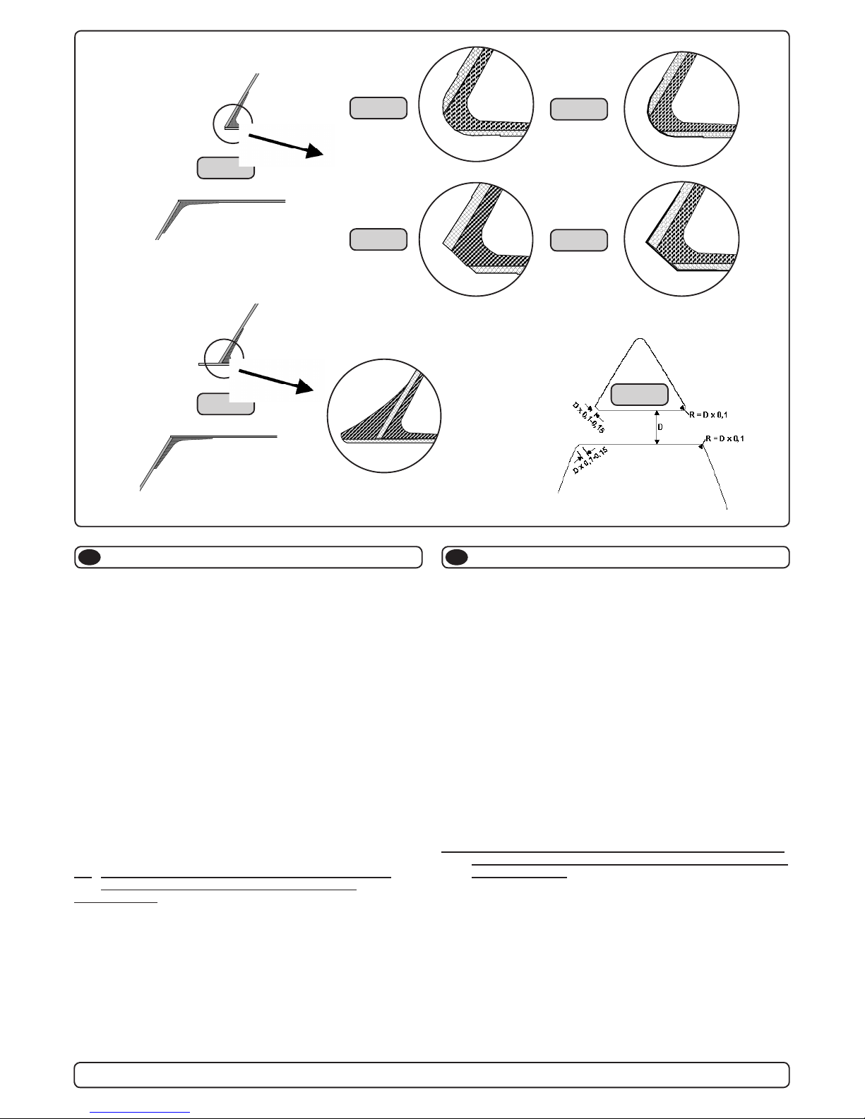
Note: Emin.: wall thickness of a standard Sidepower tunnel
Emax.: maximum wall thickness when using other GRP,
steel or aluminium tunnels
SE80/185T SE100/185T SE130/250T
Thrust [kg] 80 100 130
A [mm] 185 185 250
B [mm] 352 389 398
Cmin. [mm] 200 200 230
D [mm] 170 170 285
D recommended [mm] 340 340 560
Emin. [mm] 6 6 7
Emax. [mm] 8 8 10
Motor output [kW] 4,4 6 6,5
Voltage [V] 12/24 12/24 12/24
Weight [kg] 20 31 37
Note: Emin.: wall thickness of a standard Sidepower tunnel
Emax.: maximum wall thickness when using other GRP,
steel or aluminium tunnels
METRIC
IMPERIAL
4
SP 75 Ti / SP 95 Ti / SP 125 Ti
2.5.1- 2007
Technische Daten
D
C
Waterline
A
F
Motor: Custom made reversible DC-motor.
Gearhouse: Seawater resistant bronze. Ballbearing at
propellershaft and combination of ballbearing
and slide bearing at driveshaft.
Motor bracket: SP 75 Ti / SP 95 Ti / SP 125 Ti:
Seawaterresistant aluminium
Tunnel: Cross spun with rowing G.R.P tunnel
Steel & aluminum tunnels available at request.
Propeller: Symmetrical 4 blade propeller, fibreglass reinforced
composite.
Batteries:
Minimum recommended battery capacity
(cold crank capacity by DIN/SAE standard)
SP75Ti 12V : 550 CCA DIN/1045 CCA SAE
24V : 300 CCA DIN/570 CCA SAE
SP95Ti 12V : 750 CCA DIN/1425 CCA SAE
24V : 400 CCA DIN/760 CCA SAE
SP125Ti 12V : 750 CCA DIN/1425 CCA SAE
24V : 400 CCA DIN/760 CCA SAE
Max. use: S2 = 3 min. or appr. 7-10% within a limited time
frame.
Safety
:
Electronic time-lapse device protects against
sudden change of drive direction. Electric thermal
cut-off switch in electromotor protects against over
heating (auto reset when electro motor cools down).
Flexible coupling between electro-motor and
driveshaft protects electromotor and gearsystem
if propeller gets jammed.
If original Sidepower panel is used, the panel
shuts off automatically 6 minutes after last use.
Integrated microprocessor monitors solenoids,
reducing wear and risk of solenoid lock-in. Auto-
stop of thruster in case of accidental solenoid
lock-in or if run signal is continous for more than
3 minutes
Technical specifications
GB
SP 75 Ti SP 95 Ti SP 125 Ti
Thrust [lbs] 165 209 275
A [in] 7,28 7,28 9,84
B [in] 13,9 15,3 15,7
Cmin. [in] 7,87 7,87 9,0
D [in] 6,7 6,7 11,0
D recommended [in] 13,4 13,4 22,0
Emin. [in] 0,24 0,24 0,28
Emax. [in] 0,31 0,31 0,39
Motor output [Hp] 6 8 8,7
Voltage [V] 12/24 12/24 12/24
Weight [lbs] 44 68 77
Gear oil capacity [fl.oz]2.367 2.367 6,736
Note: Emin.: wall thickness of a standard Sidepower tunnel
Emax.: maximum wall thickness when using other GRP,
steel or aluminium tunnels
SP 75 Ti SP 95 Ti SP 125 Ti
Thrust [kg] 75 95 125
A [mm] 185 185 250
B [mm] 352 389 398
Cmin. [mm] 200 200 230
D [mm] 170 170 280
D recommended [mm] 340 340 560
Emin. [mm] 6 6 7
Emax. [mm] 8 8 10
Motor output [kW] 4,4 6 6,5
Voltage [V] 12/24 12/24 12/24
Weight [kg] 20 31 37
Gear oil capacity [ml] 70 70 200
Note: Emin.: wall thickness of a standard Sidepower tunnel
Emax.: maximum wall thickness when using other GRP,
steel or aluminium tunnels
METRICMETRIC
METRICMETRIC
METRIC
IMPERIALIMPERIAL
IMPERIALIMPERIAL
IMPERIAL
Motor: Gleichstrommotor
Getriebegeh.: Seewasserbeständige Bronze. Kugellager an
der Propellerachse, Kombination von Kugel-
und Gleitlager an der Antriebsachse.
Motorhalterung: SP 75 Ti / SP 95 Ti / SP 125 Ti:
Seewasserbeständiges Aluminium
Tunnel: Glasfibertunnel (Kreuzgewebe)
Stahl- & Aluminiumtunnel auf Anfrage.
Propeller: Symmetrischer, 4 flügeliger Kaplanpropeller aus
Glasfiberverbundmaterial.
Batterie:
Empfohlene mind. Batteriekapazität
(Kaltstartkapazität nach DIN/SAE)
SP75Ti 12V : 550 CCA DIN/1045 CCA SAE
24V : 300 CCA DIN/570 CCA SAE
SP95Ti 12V : 750 CCA DIN/1425 CCA SAE
24V : 400 CCA DIN/760 CCA SAE
SP125Ti 12V : 750 CCA DIN/1425 CCA SAE
24V : 400 CCA DIN/760 CCA SAE
Betriebszeit: S2 = 3 min. oder ca. 7-10% innerhalb eines
beliebigen Zeitraumes.
Sicherheit
:
Elektronische Zeitverzögerung zum Schutz des
Getriebes bei plötzlichem Wechsel der Drehrich-
tung. Elektrischer Thermoschalter zum Schutz
des Motors gegen Überhitzung (erneute Betriebs-
bereitschaft nach Abkühlung).
Scherstift zwischen Elektromotor und Getriebe-
achse als Schutz, wenn der Propeller blockiert
ist. Nach der letzten Benutzung schaltet das
Original Side-Power Panel automatisch nach 6
Minuten ab. Der integrierte Mikroprozessor
überwacht das Relais und reduziert sowohl
Verschleiß, als auch Relaisblockade. Das
Bustrahlruder stoppt automatisch bei Relais-
Blockade, oder bei Betrieb des Bugstrahlruders
von mehr als 3 Minuten.