Side-Power SH-360 User manual

Made in Norway
©Sleipner Motor AS 2020
SLEIPNER MOTOR AS
P.O. Box 519
N-1612 Fredrikstad
Norway
www.side-power.com
Document id:
Revision:
Date:
614 6
2
Installation manual
2 019
SH
-360/300

2614 6 22 019
-
SH 360
DECLARATION OF CONFORMITY
Sleipner Motor AS
P.O. Box 519, Arne Svendsensgt. 6-8
N-1612 Fredrikstad, Norway
Declare that this product with accompanying standard control systems complies with
the essential health and safety requirements according to:
DIRECTIVE 2013/53/EU
DIRECTIVE 2014/30/EU
DIRECTIVE 2014/35/EU
MC_0020
Installation instructions
Planning Considerations and Precautions................................. 3
Thruster Measurements ........................................................... 4
Thruster Specications ............................................................. 5
Technical Specications ........................................................... 5
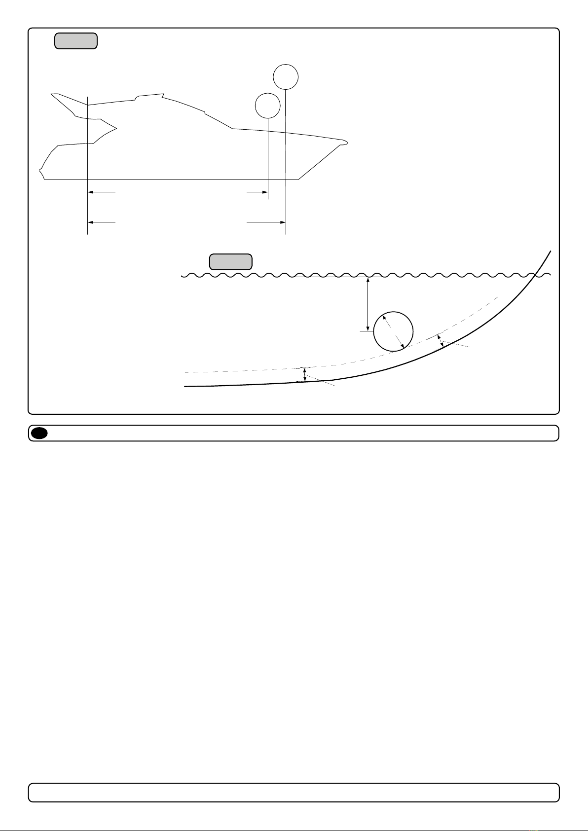
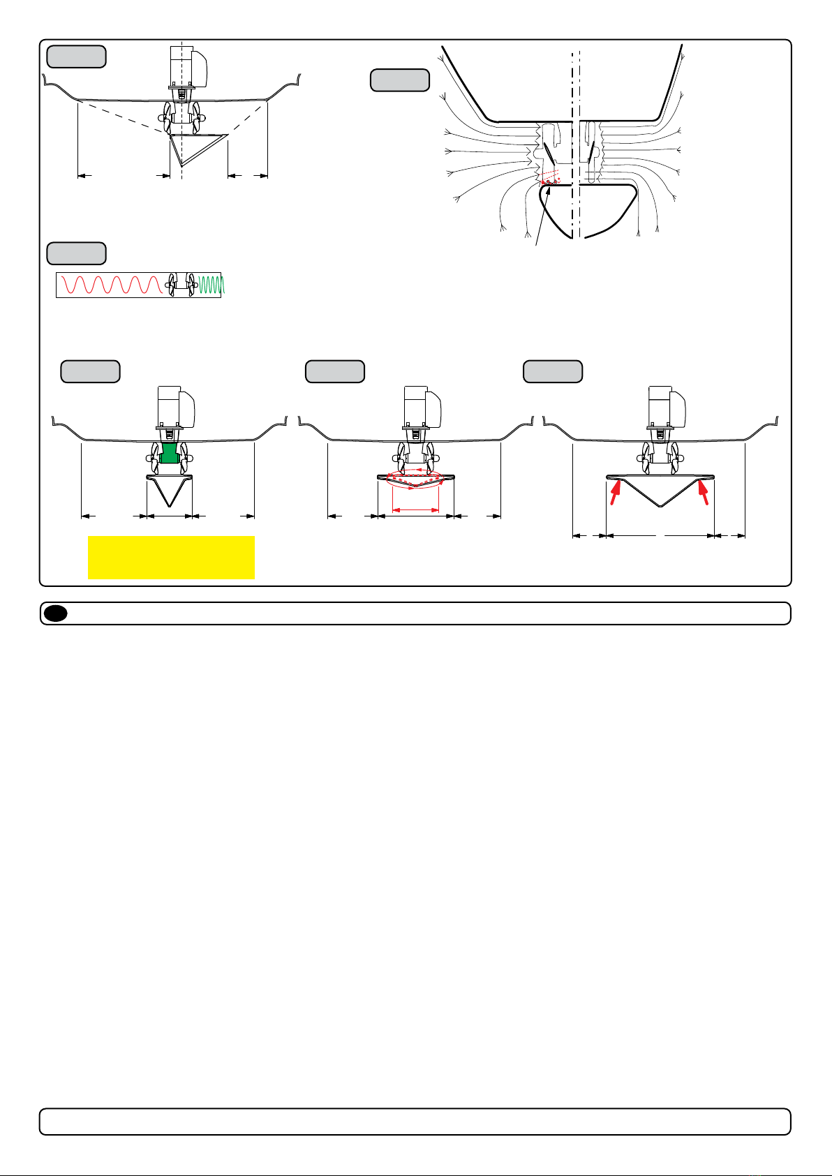
Positioning of the tunnel/ thruster.............................................. 6
Tunnel Length............................................................................ 7
Tunnel Installation in Sailboats.................................................. 8
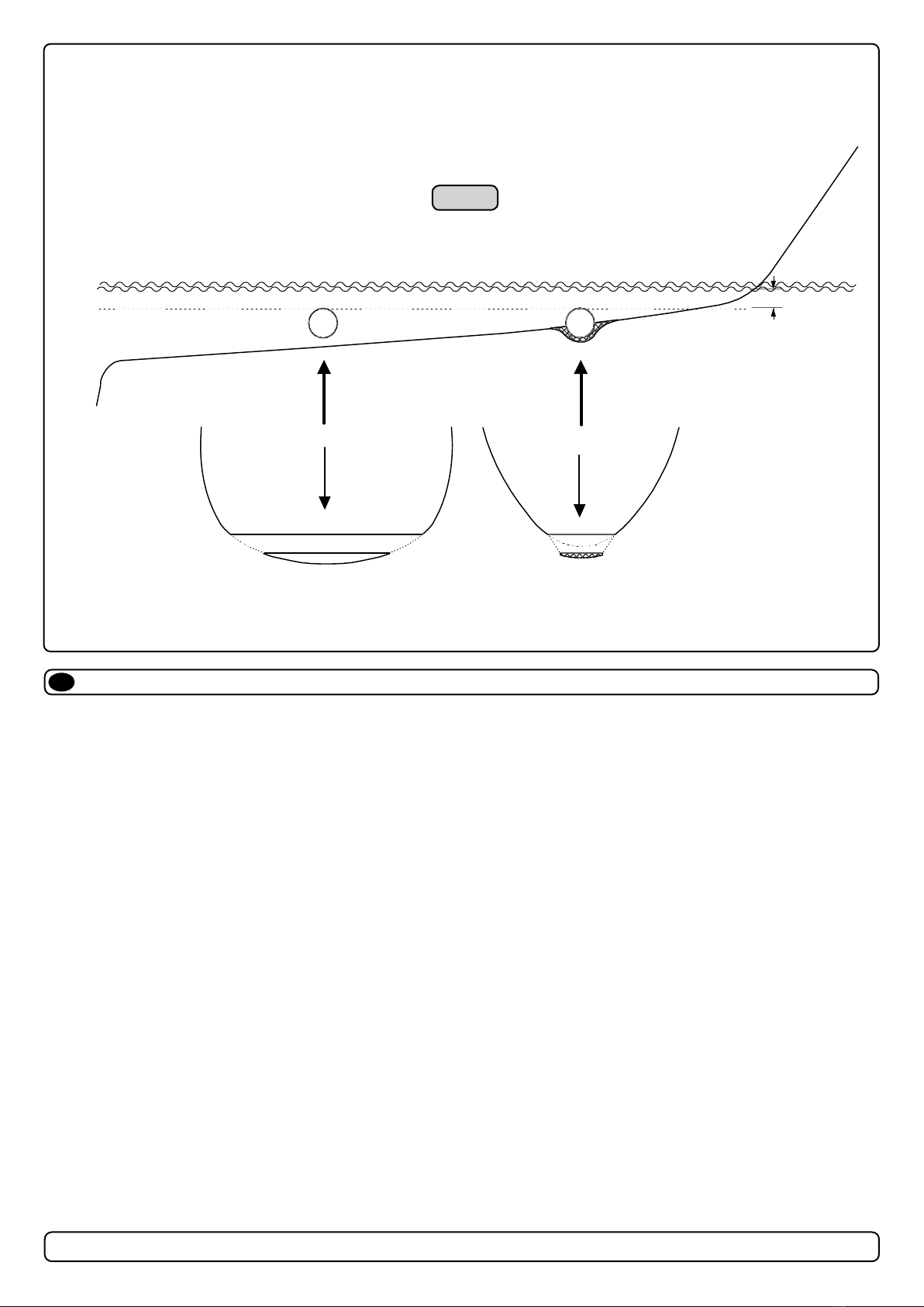
Water Deection ........................................................................ 9
Tunnel ends............................................................................. 10
Tunnel Installation ............................................................ 11 - 12
Stern Tunnel Installation.......................................................... 13
Thruster installation
Hydraulic Thruster Installation Considerations and Precautions..
................................................................................................. 14
Technical Specications .......................................................... 15
Technical Requirements / Hydraulic hose connections to motor..
................................................................................................. 16
Gear Leg & Motor Bracket Installation .................................... 17
Propeller Installation.................................................................18
Motor Installation ......................................................................19
Oil Tank Installation ................................................................. 20
S-link Planning & Precautions ................................................ 21
Control Panel Installation..........................................................22
Checklist for Hydraulic Thrusters............................................. 23
Spare Parts............................................................................. 24
Warranty statement ............................................................... 24
Contents
EN
It is the installers responsibility
When installing Side-Power equipment to follow the outlined regulations/ classi cation rules (electrical/ mechanical) according to
international or special national regulations. Instructions in this guide cannot be guaranteed to comply with global electric/ mechanic
regulations/ classi cation rules.
It is the installers responsibility
To follow all health and safety laws in accordance with their local outlined regulations/ classi cation rules.
Before installation, it is important that the installer reads this guide to ensure necessary acquaintance with this product.
The recommendations made in this manual are guidelines ONLY, and Sleipner Motor AS (Side-Power) strongly recommend that
before installation, advice is obtained from a naval architect familiar with the particular vessel and regulations/ classi cations.
This manual is intended to support educated/ experienced staff and is therefore not suffi cient in all details for professional
installation. (NB: These instructions are only general instruction. If you are not skilled to do this work, please contact professional
installers for assistance.)
All electrical work must be done by a licensed professional.
IMPORTANT
Faulty installation of the tunnel, thruster or panel will render all warranty given by Sleipner Motor AS void. MC_0038

3
614 6 22 019
-
SH 360
MC_0113
Planning Considerations and Precautions
EN
• Do not install the thruster in a position where you need to cut a stiff ener/ stringer/ support for the hull integrity without checking with the boat builder
this can be done safely.
• The motor, its components, contacts/ plugs or other joints in the control cables must be mounted so they will remain dry at all times.
• We advise painting the thruster with primer and antifouling. (NB: Do not paint the anodes, sealings or propeller shafts)
• Do not nish the inside of the tunnel with a layer of gelcoat/ topcoat or similar. There is only room for a thin coat of primer and two layers of anti-fouling
between the tunnel and the props.
• keep installation within advised measurements. The entire surface is hard coated seawater resistant aluminium. Do not damage/penetrate the coat.
• The oil tank is placed higher than the pumps to ensure enough gravity feed and pressure for feed ports. (NB: The height of oil levels in the
hydraulic tank should be higher than the connected hydraulic pumps.)
• Find a suitable location for the hydraulic tank installation for future maintenance accessibility. There must be enough space around the oil tank to
change lters, ll oil and inspect gauges and indicators.
It is the installers responsibility
When installing Side-Power equipment to follow the outlined regulations/ classi cation rules (electrical/ mechanical) according to
international or special national regulations. Instructions in this guide cannot be guaranteed to comply with global electric/ mechanic
regulations/ classi cation rules.
It is the installers responsibility
To follow all health and safety laws in accordance with their local outlined regulations/ classi cation rules.
Before installation, it is important that the installer reads this guide to ensure necessary acquaintance with this product.
The recommendations made in this manual are guidelines ONLY, and Sleipner Motor AS (Side-Power) strongly recommend that
before installation, advice is obtained from a naval architect familiar with the particular vessel and regulations/ classi cations.
This manual is intended to support educated/ experienced staff and is therefore not suffi cient in all details for professional
installation. (NB: These instructions are only general instruction. If you are not skilled to do this work, please contact professional
installers for assistance.)
All electrical work must be done by a licensed professional.
IMPORTANT
Faulty installation of the tunnel, thruster or panel will render all warranty given by Sleipner Motor AS void. MC_0038

4614 6 22 019
-
SH 360
MG_0078
TL
WD
ID
T
Propeller position will vary
on the model
The gear leg must never extend
out of the tunnel
Tunnel centre line
Twin Propeller
H
W
L
MC_0214
Thruster Measurements
EN
Measurement
code Measurement description mm inch
ID Internal tunnel diameter 300 11.81
H Motor Height 356 14.02
W Width 258 10.16
L Length 258 10.16
WD Water Depth 450 17.72
TL Minimum tunnel length 370 14.57
TL (recommended) Recommended tunnel length 550 21.65
T (min) Minimum tunnel wall thickness 10 0.39
T (max) Maximum tunnel wall thickness
*360

5
614 6 22 019
-
SH 360
MC_0056
Technical Specifi cations
EN
Motor: Hydraulic type (speci cations above).
Gearhouse: Seawater resistant bronze. Ballbearing at propeller shaft and a combination of ball bearing and slide bearing at driveshaft.
Gears: Hardened precision gears
Lubrication: Oil bath from tank (gear oil EP 90)
Bearings: Angular contact ball bearing at propellershaft and combination of ball bearing and needle bearing at driveshaft.
Motor bracket: Seawater resistant aluminium, galvanically insulated from the motor.
Tunnel: Cross spun with rowing G.R.P tunnel
Steel & aluminium tunnels available at request.
Propeller: SH 100/ SH 160/ SH 240/ SH 320/ SH 360: 5-blade skewback “Q-prop” propeller, breglass reinforced composite.
SH 420/ SH 550 Symmetrical 4 blade kaplan propeller, breglass reinforced composite.
Safety: Flexible coupling between hydraulic-motor and driveshaft protects gearsystem if propeller jams.
MG_0078
TL
WD
ID
T
Propeller position will vary
on the model
The gear leg must never extend
out of the tunnel
Tunnel centre line
Twin Propeller
H
WL
MC_0214
Thruster Measurements
EN
Measurement
code Measurement description mm inch
ID Internal tunnel diameter 300 11.81
H Motor Height 356 14.02
W Width 258 10.16
L Length 258 10.16
WD Water Depth 450 17.72
TL Minimum tunnel length 370 14.57
TL (recommended) Recommended tunnel length 550 21.65
T (min) Minimum tunnel wall thickness 10 0.39
T (max) Maximum tunnel wall thickness
*360
MC_0215
Thruster Specifi cations
EN
description * 360
light duty thrust up to (kg * lbs) 360kg * 795lbs
Heavy duty thrust up to (kg * lbs) 270kg * 594lbs
Typical Boat Size (m * ft) 18m - 33m * 59ft - 108ft
Propulsion System Twin Counter Rotating
Power (kw * Hp) 27kw * 37hp
Weight (kg * lbs) 26 kg * 57.32 lbs
Lubrication Sealed

6614 6 22 019
-
SH 360
important
MG_0001
A
B
Pivot
point
1
Ø
2
Lowered rotation power performance
Stronger rotation power performance
min 1/4
Ø
(Recommended)
min 1/4
Ø
(Recommended)
WD
Water line
Positioning of the tunnel / thruster
EN MC_0003
Aim to install the thruster as far forward as possible (1)
Due to the leverage eff ect around the boats’ pivot point. The distance diff erence from the boat pivots’ point to the thruster will determine the amount of
real rotation power for the boat.
Aim to install the thruster as deep as possible under the waterline (2)
Deeper installations prevent air from being sucked into the tunnel from the surface, resulting in reduced thrust performance and increase noise levels
during operation. Deeper installations increase water pressure for maximum effi ciency from the thruster.
The centre of the tunnel should be a minimum of 1 x the tunnel diameter below the waterline. The installer must make evaluations based on thruster
performance, boat type and operating conditions. As a general recommendation, the position of the tunnel should not be a minimum of 1/4 of the
diameter of the tunnel from the boat keel. (NB: This can be overlooked depending on the installation methods defi ned in this manual.)

7
614 6 22 019
-
SH 360
MC_0003
1
2
3
4 65
MG_0048
Increase tunnel length to protect
the propeller from water forces
when high-speed cruising.
Water
Forces
Increase tunnel length to prevent
a circular water vacuum cavity
between the propeller and the
hull of the boat.
STANDARD USE FLAT BOTTOM HULL HIGH-SPEED OPERATION
Ensure the top and bottom tunnel lengths are respectable
lengths from one another.
Cavitation
Water flow must have
space to "straighten"
itself for best
performance.
IMPORTANT
The gear leg must never
extend out of the tunnel
Tunnel Length
EN
Optimal tunnel length
Correct tunnel lengths depend on many factors from the hull type, operation and environmental conditions.
Tunnels should avoid being longer than 4 x the tunnel diameter as this will reduce thruster performance. (NB: Installing long length tunnels can fl ex/
bend over time and may require additional support. Consult with a naval architect.)
1. Ensure the top and bottom tunnel lengths are respectable lengths from one another.
2. If the tunnel is too long, the friction inside will reduce the water speed and thereby the thrust.
3. If the tunnel is too short (typically only in the bottom section of the tunnel) cavitation problems can occur as water ow will not be able to
“straighten” itself before reaching the propeller. This cavitation will reduce performance and increase noise during operation.
Thruster within the tunnel
It is important the propellers and the lower unit/ gear leg must be entirely inside the thruster tunnel. Propellers that protrude from the tunnel will not
perform as intended.
4. Standard Use
Tunnel length must be long enough to ensure the propellers are not extruding the tunnel.
5. Flat Bottom Hull
Tunnel lengths must be longer than the standard measurement outlined within the manual to ensure a circular vacuum is not created between the
thruster and the bottom of the boat.
6. High-Speed Boats
Tunnel lengths must be increased to protect the propeller from damage when crashing against the water surface during high-speed cruising. (NB:
This can include the length of a spoiler)
important
MG_0001
A
B
Pivot
point
1
Ø
2
Lowered rotation power performance
Stronger rotation power performance
min 1/4
Ø
(Recommended)
min 1/4
Ø
(Recommended)
WD
Water line
Positioning of the tunnel / thruster
EN MC_0003
Aim to install the thruster as far forward as possible (1)
Due to the leverage eff ect around the boats’ pivot point. The distance diff erence from the boat pivots’ point to the thruster will determine the amount of
real rotation power for the boat.
Aim to install the thruster as deep as possible under the waterline (2)
Deeper installations prevent air from being sucked into the tunnel from the surface, resulting in reduced thrust performance and increase noise levels
during operation. Deeper installations increase water pressure for maximum effi ciency from the thruster.
The centre of the tunnel should be a minimum of 1 x the tunnel diameter below the waterline. The installer must make evaluations based on thruster
performance, boat type and operating conditions. As a general recommendation, the position of the tunnel should not be a minimum of 1/4 of the
diameter of the tunnel from the boat keel. (NB: This can be overlooked depending on the installation methods defi ned in this manual.)

8614 6 22 019
-
SH 360
MG_0004
Min
Pos. B
Pos. A
1
1
2
3
4 65
MG_0048
Increase tunnel length to protect
the propeller from water forces
when high-speed cruising.
Water
Forces
Increase tunnel length to prevent
a circular water vacuum cavity
between the propeller and the
hull of the boat.
STANDARD USE FLAT BOTTOM HULL HIGH-SPEED OPERATION
Ensure the top and bottom tunnel lengths are respectable
lengths from one another.
Cavitation
Water flow must have
space to "straighten"
itself for best
performance.
IMPORTANT
The gear leg must never
extend out of the tunnel
Tunnel installation in sailboats
EN
Some sailboats have a at bottom and shallow draft in the bow section. This can make installing the thruster as far forward from the boats main pivot
point diffi cult. (Fig. 1).
However, it is possible to install a tunnel thruster in most sailboats, even when the hull does not directly support the tting of a tunnel.
Instead t the tunnel halfway into the underneath section of the existing hull. Strengthen it with a de ector/ spoiler directing the water ow around the
tunnel. This will allow installation of the thruster in the proper position on the boat, maintaining the reliability and space advantages of the tunnel thruster.
This installation is being used by some of the world’s largest sailboat builders and has proven to give little to no speed loss during normal cruising. This
can also be an installation method for at bottomed barges to avoid extremely long tunnels and large oval tunnel openings in the hull.
MC_0003

9
614 6 22 019
-
SH 360
MG_0003
High water force
while underway
High water force
while underway
from wave contact
1 2 3
4
Water Defl ection
EN MC_0003
1. A possible problem in sailboats or fast powerboats is that a non-rounded surface can generate drag from the back face of the tunnel, as it creates a
“ at” area facing the ow of water (1).
This problem can be solved in two diff erent ways, depending on what is possible or easier to perform.
2. The best solution which generally reduces the most drag is to make a recess in the hull at the back of the tunnel. As the back face is removed
water can ow freely past the tunnel entry. The depth and shape of this recess will depend on the boat and the angle facing up/ down aft of the
tunnel insert. Normally it is angled slightly down because of the water ow on this area (2).
3. Making a de ector/ spoiler in front and underneath the tunnel can also reduce damage to the thruster and drag. The de ector/ spoiler will push the
water ow out from the hull so water can pass by the back face of the tunnel. The shape and size of this de ector/ spoiler will depend on the hull
shape. The easiest way of making the de ector/ spoiler is to retain a part of the lower forward area of the tunnel while installing the tube. Use this
area as support to mould a soft curve/spoiler shape from the hull. (3).
4. The thruster propeller can spin (passively) producing noise while sailing or cruising as water is forced through the tunnel. Water ow directed
through the tunnel at high speeds, during turning or as the boat bumps waves while underway can also damage the thruster (4).
(NB: As a rule, you should not see the back face of the tunnel when standing directly in front of the boat looking aft.)
MG_0004
Min
Pos. B
Pos. A
1
1
2
3
4 65
MG_0048
Increase tunnel length to protect
the propeller from water forces
when high-speed cruising.
Water
Forces
Increase tunnel length to prevent
a circular water vacuum cavity
between the propeller and the
hull of the boat.
STANDARD USE FLAT BOTTOM HULL HIGH-SPEED OPERATION
Ensure the top and bottom tunnel lengths are respectable
lengths from one another.
Cavitation
Water flow must have
space to "straighten"
itself for best
performance.
IMPORTANT
The gear leg must never
extend out of the tunnel
Tunnel installation in sailboats
EN
Some sailboats have a at bottom and shallow draft in the bow section. This can make installing the thruster as far forward from the boats main pivot
point diffi cult. (Fig. 1).
However, it is possible to install a tunnel thruster in most sailboats, even when the hull does not directly support the tting of a tunnel.
Instead t the tunnel halfway into the underneath section of the existing hull. Strengthen it with a de ector/ spoiler directing the water ow around the
tunnel. This will allow installation of the thruster in the proper position on the boat, maintaining the reliability and space advantages of the tunnel thruster.
This installation is being used by some of the world’s largest sailboat builders and has proven to give little to no speed loss during normal cruising. This
can also be an installation method for at bottomed barges to avoid extremely long tunnels and large oval tunnel openings in the hull.
MC_0003

10 614 6 22 019
-
SH 360
MG_0002
R = 0,1 x D (10%)
D
12
3
Angled tunnel ends for
steel/ aluminium hulls
Cavitation
MG_0003
High water force
while underway
High water force
while underway
from wave contact
1 2 3
4
Tunnel ends
EN MC_0003
Rounded tunnel ends will maximise thrust and minimise noise and cavitation.
For best preformance round the tunnel connection to the hull-side as much as possible. The minimum rounding has a radius of 10% of the diameter of
the tunnel.
Signi cant advantages of a rounded tunnel over a sharp tunnel to hull connections are:
1. A rounded tunnel end will prevent the creation of turbulence/ cavitation created from a sharp tunnel end when water passes by fast.
- The turbulence/ cavitation will block the outer area of the tunnel and thereby reduces the eff ective tunnel diameter and thrust.
- The turbulence/ cavitation hits the propeller and will lessen the propellers performance and create excess noise.
2. For steel/ aluminium hulls angled tunnel ends also off er similar performance as a rounded connection.
3. A rounded tunnel end makes the thruster draw water from along the hull-side, creating a vacuum that will suck the boat sideways and thereby give
additional thrust.
- With a sharp tunnel end, the thruster will be unable to take water from along the hull-side, and you will not gain the desired vacuum and
additional thrust. This “free” extra thrust in optimal installations be 30 - 40% of the total thrust.
(NB: A Side-power thruster propeller does not produce cavitation at working speed. Therefore, any cavitation and cavitation noise in the
tunnel will be caused during improper tunnel installation.)

11
614 6 22 019
-
SH 360
MG_0005
R
D
1 2
34
6
5
8 x layers of fibreglass
and resin
8 x layers of fibreglass
and resin
MG_0006
R = D x 0,1
R = D x 0,1
Dx0,1-0,15
Dx0,1-0,15
D
Layers of
fibreglass
and resin
Layers of
fibreglass
and resin
*Fibreglass
Hull
*Steel/
Aluminium
Hull
Hull
Hull
Hull
Tunnel
Tunnel
Tunnel
Welding
Layers of
fibreglass
and resin
Additional Layers of
fibreglass and resin
Additional Layers of
fibreglass and resin
Hull
1 3
4
2
Tunnel installation
EN
1. Find the position in the boat considering the information earlier in this manual and the applicable measurements for the thruster model you are
installing. Mark the centre of the tunnel on both sides of the hull. Drill a hole horizontally at these marks.
2. Mark the circle for the tunnel opening (outside diameter of the tunnel) and cut the hole.
3. Grind off the the gel coat to the “real breglass” area 12cm around the hole on both inside and outside the hull to cast the tunnel to the hull (Fig. 3).
4. Insert the tunnel and mark its shape to t the hull. (NB: if you are installing with a defl ector/ spoiler, leave a part of the tunnel in the front and
underside of the tunnel that will cover the back face.)
5. Cut the tunnel ends to the desired shape and lightly sand its surface and clean with acetone or similar where you are going to apply breglass.
(NB: Do not cast/ fi breglass on the area were the thruster will be placed.)
6. Cast the tunnel to the inside of the hull, use at least eight layers of 300g breglass and resin, preferably alternating mat and rowing types of
breglass. To round the tunnel ends to a 10% radius make further layers inside to preserve the desired hull thickness.
(NB: Ensure gaps between the tunnel and the hull are completely fi lled with resin/ fi breglass. In areas where you can not access to make
layers of resin/ fi breglass, a resin/ fi breglass mixture must be used in that area.)
MC_0003
IMPORTANT
We recommend that a professional does the fi breglass, steel or aluminium fi tting of the tunnel. These instructions are only general
instructions and do not explain in any way the details of fi breglass work. Problems caused by faulty installation of the tunnel, are the
installers full responsibility.
MG_0002
R = 0,1 x D (10%)
D
12
3
Angled tunnel ends for
steel/ aluminium hulls
Cavitation
MG_0003
High water force
while underway
High water force
while underway
from wave contact
1 2 3
4
Tunnel ends
EN MC_0003
Rounded tunnel ends will maximise thrust and minimise noise and cavitation.
For best preformance round the tunnel connection to the hull-side as much as possible. The minimum rounding has a radius of 10% of the diameter of
the tunnel.
Signi cant advantages of a rounded tunnel over a sharp tunnel to hull connections are:
1. A rounded tunnel end will prevent the creation of turbulence/ cavitation created from a sharp tunnel end when water passes by fast.
- The turbulence/ cavitation will block the outer area of the tunnel and thereby reduces the eff ective tunnel diameter and thrust.
- The turbulence/ cavitation hits the propeller and will lessen the propellers performance and create excess noise.
2. For steel/ aluminium hulls angled tunnel ends also off er similar performance as a rounded connection.
3. A rounded tunnel end makes the thruster draw water from along the hull-side, creating a vacuum that will suck the boat sideways and thereby give
additional thrust.
- With a sharp tunnel end, the thruster will be unable to take water from along the hull-side, and you will not gain the desired vacuum and
additional thrust. This “free” extra thrust in optimal installations be 30 - 40% of the total thrust.
(NB: A Side-power thruster propeller does not produce cavitation at working speed. Therefore, any cavitation and cavitation noise in the
tunnel will be caused during improper tunnel installation.)

12 614 6 22 019
-
SH 360
MG_0005
R
D
1 2
34
6
5
8 x layers of fibreglass
and resin
8 x layers of fibreglass
and resin
MG_0006
R = D x 0,1
R = D x 0,1
Dx0,1-0,15
Dx0,1-0,15
D
Layers of
fibreglass
and resin
Layers of
fibreglass
and resin
*Fibreglass
Hull
*Steel/
Aluminium
Hull
Hull
Hull
Hull
Tunnel
Tunnel
Tunnel
Welding
Layers of
fibreglass
and resin
Additional Layers of
fibreglass and resin
Additional Layers of
fibreglass and resin
Hull
1 3
4
2
IMPORTANT
Avoid all casting where the motor-bracket is to be placed, as this will cause misfi t and possible failure to the gear house.
Tunnel installation
EN
With tunnel installed and cast.
1. Round the edges with a radius of 10% of the tunnel diameter.
2. For steel/ aluminium hulls make a slope with a length of 10-15% of the tunnel diameter.
(NB: If this is not possible, round the tunnel end as much as possible.)
3. Additionally cast two layers on the outside of the tunnel/ hull in a 10cm area
4. Follow the same method if making the de ector/ spoiler.
You must apply gel coat to areas you have grounded/ moulded to make waterproof. These areas allow water access
to the hull which is typically not waterproof without these applications outside. (NB: All original Side-Power tunnels are fully waterproof when
delivered except in the areas where you have cut and bonded it to the hull.)
MC_0003

13
614 6 22 019
-
SH 360
Stern Tunnel Installation
EN
Stern thruster installation has extra considerations and precautions and thruster installation procedures.
See the attached manual supplied in the stern thruster kit
MC_0003
MG_0005
R
D
1 2
34
6
5
8 x layers of fibreglass
and resin
8 x layers of fibreglass
and resin
MG_0006
R = D x 0,1
R = D x 0,1
Dx0,1-0,15
Dx0,1-0,15
D
Layers of
fibreglass
and resin
Layers of
fibreglass
and resin
*Fibreglass
Hull
*Steel/
Aluminium
Hull
Hull
Hull
Hull
Tunnel
Tunnel
Tunnel
Welding
Layers of
fibreglass
and resin
Additional Layers of
fibreglass and resin
Additional Layers of
fibreglass and resin
Hull
1 3
4
2
IMPORTANT
Avoid all casting where the motor-bracket is to be placed, as this will cause misfi t and possible failure to the gear house.
Tunnel installation
EN
With tunnel installed and cast.
1. Round the edges with a radius of 10% of the tunnel diameter.
2. For steel/ aluminium hulls make a slope with a length of 10-15% of the tunnel diameter.
(NB: If this is not possible, round the tunnel end as much as possible.)
3. Additionally cast two layers on the outside of the tunnel/ hull in a 10cm area
4. Follow the same method if making the de ector/ spoiler.
You must apply gel coat to areas you have grounded/ moulded to make waterproof. These areas allow water access
to the hull which is typically not waterproof without these applications outside. (NB: All original Side-Power tunnels are fully waterproof when
delivered except in the areas where you have cut and bonded it to the hull.)
MC_0003

14 614 6 22 019
-
SH 360
MC_0107
Technical Specifi cations
EN
1) Max. thrust: 182kg
2) Max. thrust: 228kg
3) Max. thrust: 211kg
4) Max. thrust: 269kg
5) Max. thrust: 302kg
6) Max. thrust: 307kg
7) Max. thrust: 310kg
8) Max. thrust: 370kg
9) Max. thrust: 399kg
60 % 80 % 100 %
Thruster model Motor type Flow Pressure Flow Pressure Flow Pressure
SH 100
U6 L/min -Bar 18.8 103 21.7 137 24.2 172
USG-PSI 5.0 1494 5.7 1987 6.4 2494
U8 L/min -Bar 25.5 77 29,9 103 32,3 129
USG-PSI 6.6 1117 7.6 1494 8.5 1871
U10 L/min -Bar 31.3 62 36.1 82 40.4 103
USG-PSI 8.3 899 9.5 1189 10.7 1494
SH 160
U6 L/min -Bar 18.6 150 21,5 200 24 250
USG-PSI 4.9 2175 5.7 2900 6.3 3625
U8 L/min -Bar 24,8 112 28.6 150 32.0 187
USG-PSI 6.6 1624 7.6 2175 8.5 2712
U10 L/min -Bar 31.0 82 35.8 120 40,0 150
USG-PSI 8.2 1305 9.5 1740 10.6 2172
U11 L/min - Bar 34.1 82 39.3 109 44.0 136
USG-PSI 9.0 1189 10.4 1581 11.6 1972
U14 L/min -Bar 43.1 64 49.7 86 55,6 107
USG-PSI 11.4 928 13.1 1247 14.7 1552
SH 240
U8 L/min -Bar 19.1 217 21.4 275 21,4 2751)
USG-PSI 5.05 3147 5.65 3988 5.65 39881)
U10 L/min -Bar 23.8 174 27.5 232 30 2752)
USG-PSI 6.29 2523 7.23 3364 7.93 39882)
U11 L/min -Bar 26.2 158 30.2 211 33,8 264
USG-PSI 6.9 2291 8.0 3060 8.9 3828
U14 L/min -Bar 33.1 124 38.2 166 42.7 207
USG-PSI 8.7 1798 10.1 2407 11.3 3002
U16 L/min -Bar 38.1 109 44.0 145 49.2 181
USG-PSI 10.1 1581 11.6 2103 13.0 2625
U19 L/min -Bar 45.1 92 52.1 122 58.3 153
USG-PSI 11.9 1334 13.8 1769 15.4 2219
SH320
U11 L/min -Bar 23.8 249 24.9 274 24.9 2743)
USG-PSI 6.29 3611 6.58 3973 6.58 39733)
U14 L/min -Bar 30.1 196 34.7 261 35.6 2744)
USG-PSI 7.95 2842 9.17 3785 9.41 39734)
U16 L/min -Bar 34.6 171 39.9 229 43.7 2746)
USG-PSI 9.14 2480 10.54 3321 11.55 39736)
BA16 L/min -Bar 33.8 172 39.0 230 43.6 287
USG-PSI 8.93 2494 10.30 3335 11.52 4162
U19 L/min -Bar 41.0 144 47.3 193 52.9 241
USG-PSI 10.83 2088 12.50 2799 13.98 3495
BA19 L/min -Bar 40.1 145 46.3 194 51.8 242
USG-PSI 10.59 2103 11.44 2813 13.69 3509
U23 L/min -Bar 49.4 121 57 162 63.8 202
USG-PSI 13.05 1755 15.06 2349 16.86 2929
SH360
U19 L/min -Bar 46.5 177 53.7 236 55 2485)
USG-PSI 12.3 2567 14.17 3423 14.53 35975)
BA19 L/min -Bar 45.3 176 52.3 234 58.5 293
USG-PSI 11.97 2553 13.82 3394 15.45 4250
U23 L/min -Bar 56,3 146 65.1 195 310 3107)
USG-PSI 14.88 2118 17.2 2828 81.89 44967)
BA23 L/min -Bar 54.5 146 62.3 196 70.3 245
USG-PSI 14.4 2118 16.46 2843 18.57 3553
SH400
U19 L/min -Bar 43.5 195 50.2 260 54.2 3028)
USG-PSI 11.49 2828 13.26 3771 14.32 43808)
BA23 L/min -Bar 52.3 163 60.4 218 67.5 272
USG-PSI 13.82 2364 15.96 3162 17.83 3945
SH 420
U26 L/min -Bar 44.7 188 51.6 251 56.2 2989)
USG-PSI 11.81 2726 13.63 3640 14.85 43219)
U29 L/min -Bar 49.8 169 57.6 225 64.3 281
USG-PSI 13.16 2450 15.22 3263 16.99 4075
BA32 L/min -Bar 48.4 151 55.8 202 62.4 252
USG-PSI 12.78 2190 14.74 2929 16.49 3654
U33 L/min -Bar 56.1 148 64.7 198 72.4 247
USG-PSI 14.82 2146 17.09 2871 19.13 3582
U37 L/min -Bar 62.1 132 71.8 176 80.2 220
USG-PSI 16.41 1914 18.97 2552 21.19 3190
BA40 L/min -Bar 61 121 70.4 161 78.7 202
USG-PSI 16.12 1755 18.6 2335 20.79 2929
SH550
BA40 L/min -Bar 69.8 158 80.5 211 90 264
USG-PSI 18.44 2291 21.27 3060 23.78 3828
P42 L/min -Bar 84.2 152 97.2 203 108.7 254
USG-PSI 22.25 2204 25.68 2944 28.72 3683
G45 L/min -Bar 89.5 142 103.4 190 115.6 237
USG-PSI 23.65 2059 27.32 2755 30.54 3437
BA45 L/min -Bar 77.8 139 89.9 185 100.5 232
USG-PSI 20.56 2016 23.75 2683 26.55 3364
U50 L/min -Bar 95 128 109.7 171 122.7 213
USG-PSI 25.10 1856 28.98 2480 32.42 3089
P52 L/min -Bar 105.1 124 121.4 166 135.7 207
USG-PSI 27.77 1798 27.77 2407 35.85 3002
BA60 L/min -Bar 104.6 106 120.8 141 135.1 176
USG-PSI 27.64 1537 31.92 2045 35.69 2552
MC_0009
Hydraulic Thruster Installation Considerations and Precautions
EN
Before installation, The installer must read this guide to ensure necessary acquaintance with this product.
• If the height of the room you are installing the Side-Power is limited, it can be installed horizontally or at any angle in-between.
- If the electromotor is positioned more than 30º off vertical, it must be supported separately.
- The electromotor must be handled with care. Do not lift it by internal connections/ main terminals or bed placed down on the driveshaft.
- Beware of keeping installation within advised measurements. No part of the propeller or gear house must be outside the tunnel.
• Do not install the thruster in a position where you need to cut a stiff ener/ stringer/ support for the hull integrity without checking with the boat builder
this can be done safely.
• The electromotor, its components, contacts/ plugs or other joints in the control cables must be mounted so they will remain dry at all times.
• We advise painting the gear house and propellers with antifouling. (NB: Do not paint the anodes, sealings or propeller shafts)
• Do not nish the inside of the tunnel with a layer of gel coat/ topcoat or similar. There is only room for a thin coat of primer and two layers of
anti-fouling between the tunnel and the props.
• With the boat on land, run the thruster for a fraction of a second, as without resistance it will accelerate very fast to a damaging rpm.
• While the thruster is in the air, ensure that the propellers have come to a complete stop before performing a directional change of the thruster, as it
might cause damage to the thruster.
If an original Side-Power hydraulic system is NOT installed, please ensure the following:
• Install an oil lter to keep the oil clean.
• Fit an oil cooler or use an oil tank to ensure the maximum oil temperature is 43 - 50 degrees Celcius.
• Hydraulic thrusters are supplied with hydraulic motors only.
• The installed hydraulic system is the responsibility of the tter/ installer and must be within the limitations outlined in this manual to ensure no damage
is caused to the thruster.
• The hydraulic valve must have ow and pressure limits that are either set within or can be adjusted to the limits of the thrusters capability.
• We strongly advise that a shock valve is tted and set to 10% - 15% above the chosen maximum pressure set in the valve. This will prevent the
system from being damaged if the propellers are blocked for any reason.
• It is required that a device is installed to ensure that the drive direction cannot be suddenly changed, as this can severely damage the gear house.
(NB: By adding an electronic time-lapse/delay safety on the electric control system or by using a valve that has this type of protection built
in will prevent this issue. *The required time delay is 1 second.)
IMPORTANT
If installing S-link products DO NOT connect any other control equipment to the S-link controlled products except Side-Power original
S-link products or via a Side-Power supplied interface product made for interfacing with other controls. Any attempt to directly control or
at all connect into the S-link control system without the designated and approved interface will render all warranties and responsibilities
for the complete line of Side-Power products connected void and null. If you are interfacing by agreement with Sleipner and through a
designated Side-Power supplied interface, you are still required to also install at least one original Side-Power control panel to enable
effi cient troubleshooting if necessary.

15
614 6 22 019
-
SH 360
MC_0107
Technical Specifi cations
EN
1) Max. thrust: 182kg
2) Max. thrust: 228kg
3) Max. thrust: 211kg
4) Max. thrust: 269kg
5) Max. thrust: 302kg
6) Max. thrust: 307kg
7) Max. thrust: 310kg
8) Max. thrust: 370kg
9) Max. thrust: 399kg
60 % 80 % 100 %
Thruster model Motor type Flow Pressure Flow Pressure Flow Pressure
SH 100
U6 L/min -Bar 18.8 103 21.7 137 24.2 172
USG-PSI 5.0 1494 5.7 1987 6.4 2494
U8 L/min -Bar 25.5 77 29,9 103 32,3 129
USG-PSI 6.6 1117 7.6 1494 8.5 1871
U10 L/min -Bar 31.3 62 36.1 82 40.4 103
USG-PSI 8.3 899 9.5 1189 10.7 1494
SH 160
U6 L/min -Bar 18.6 150 21,5 200 24 250
USG-PSI 4.9 2175 5.7 2900 6.3 3625
U8 L/min -Bar 24,8 112 28.6 150 32.0 187
USG-PSI 6.6 1624 7.6 2175 8.5 2712
U10 L/min -Bar 31.0 82 35.8 120 40,0 150
USG-PSI 8.2 1305 9.5 1740 10.6 2172
U11 L/min - Bar 34.1 82 39.3 109 44.0 136
USG-PSI 9.0 1189 10.4 1581 11.6 1972
U14 L/min -Bar 43.1 64 49.7 86 55,6 107
USG-PSI 11.4 928 13.1 1247 14.7 1552
SH 240
U8 L/min -Bar 19.1 217 21.4 275 21,4 2751)
USG-PSI 5.05 3147 5.65 3988 5.65 39881)
U10 L/min -Bar 23.8 174 27.5 232 30 2752)
USG-PSI 6.29 2523 7.23 3364 7.93 39882)
U11 L/min -Bar 26.2 158 30.2 211 33,8 264
USG-PSI 6.9 2291 8.0 3060 8.9 3828
U14 L/min -Bar 33.1 124 38.2 166 42.7 207
USG-PSI 8.7 1798 10.1 2407 11.3 3002
U16 L/min -Bar 38.1 109 44.0 145 49.2 181
USG-PSI 10.1 1581 11.6 2103 13.0 2625
U19 L/min -Bar 45.1 92 52.1 122 58.3 153
USG-PSI 11.9 1334 13.8 1769 15.4 2219
SH320
U11 L/min -Bar 23.8 249 24.9 274 24.9 2743)
USG-PSI 6.29 3611 6.58 3973 6.58 39733)
U14 L/min -Bar 30.1 196 34.7 261 35.6 2744)
USG-PSI 7.95 2842 9.17 3785 9.41 39734)
U16 L/min -Bar 34.6 171 39.9 229 43.7 2746)
USG-PSI 9.14 2480 10.54 3321 11.55 39736)
BA16 L/min -Bar 33.8 172 39.0 230 43.6 287
USG-PSI 8.93 2494 10.30 3335 11.52 4162
U19 L/min -Bar 41.0 144 47.3 193 52.9 241
USG-PSI 10.83 2088 12.50 2799 13.98 3495
BA19 L/min -Bar 40.1 145 46.3 194 51.8 242
USG-PSI 10.59 2103 11.44 2813 13.69 3509
U23 L/min -Bar 49.4 121 57 162 63.8 202
USG-PSI 13.05 1755 15.06 2349 16.86 2929
SH360
U19 L/min -Bar 46.5 177 53.7 236 55 2485)
USG-PSI 12.3 2567 14.17 3423 14.53 35975)
BA19 L/min -Bar 45.3 176 52.3 234 58.5 293
USG-PSI 11.97 2553 13.82 3394 15.45 4250
U23 L/min -Bar 56,3 146 65.1 195 310 3107)
USG-PSI 14.88 2118 17.2 2828 81.89 44967)
BA23 L/min -Bar 54.5 146 62.3 196 70.3 245
USG-PSI 14.4 2118 16.46 2843 18.57 3553
SH400
U19 L/min -Bar 43.5 195 50.2 260 54.2 3028)
USG-PSI 11.49 2828 13.26 3771 14.32 43808)
BA23 L/min -Bar 52.3 163 60.4 218 67.5 272
USG-PSI 13.82 2364 15.96 3162 17.83 3945
SH 420
U26 L/min -Bar 44.7 188 51.6 251 56.2 2989)
USG-PSI 11.81 2726 13.63 3640 14.85 43219)
U29 L/min -Bar 49.8 169 57.6 225 64.3 281
USG-PSI 13.16 2450 15.22 3263 16.99 4075
BA32 L/min -Bar 48.4 151 55.8 202 62.4 252
USG-PSI 12.78 2190 14.74 2929 16.49 3654
U33 L/min -Bar 56.1 148 64.7 198 72.4 247
USG-PSI 14.82 2146 17.09 2871 19.13 3582
U37 L/min -Bar 62.1 132 71.8 176 80.2 220
USG-PSI 16.41 1914 18.97 2552 21.19 3190
BA40 L/min -Bar 61 121 70.4 161 78.7 202
USG-PSI 16.12 1755 18.6 2335 20.79 2929
SH550
BA40 L/min -Bar 69.8 158 80.5 211 90 264
USG-PSI 18.44 2291 21.27 3060 23.78 3828
P42 L/min -Bar 84.2 152 97.2 203 108.7 254
USG-PSI 22.25 2204 25.68 2944 28.72 3683
G45 L/min -Bar 89.5 142 103.4 190 115.6 237
USG-PSI 23.65 2059 27.32 2755 30.54 3437
BA45 L/min -Bar 77.8 139 89.9 185 100.5 232
USG-PSI 20.56 2016 23.75 2683 26.55 3364
U50 L/min -Bar 95 128 109.7 171 122.7 213
USG-PSI 25.10 1856 28.98 2480 32.42 3089
P52 L/min -Bar 105.1 124 121.4 166 135.7 207
USG-PSI 27.77 1798 27.77 2407 35.85 3002
BA60 L/min -Bar 104.6 106 120.8 141 135.1 176
USG-PSI 27.64 1537 31.92 2045 35.69 2552
MC_0009
Hydraulic Thruster Installation Considerations and Precautions
EN
Before installation, The installer must read this guide to ensure necessary acquaintance with this product.
• If the height of the room you are installing the Side-Power is limited, it can be installed horizontally or at any angle in-between.
- If the electromotor is positioned more than 30º off vertical, it must be supported separately.
- The electromotor must be handled with care. Do not lift it by internal connections/ main terminals or bed placed down on the driveshaft.
- Beware of keeping installation within advised measurements. No part of the propeller or gear house must be outside the tunnel.
• Do not install the thruster in a position where you need to cut a stiff ener/ stringer/ support for the hull integrity without checking with the boat builder
this can be done safely.
• The electromotor, its components, contacts/ plugs or other joints in the control cables must be mounted so they will remain dry at all times.
• We advise painting the gear house and propellers with antifouling. (NB: Do not paint the anodes, sealings or propeller shafts)
• Do not nish the inside of the tunnel with a layer of gel coat/ topcoat or similar. There is only room for a thin coat of primer and two layers of
anti-fouling between the tunnel and the props.
• With the boat on land, run the thruster for a fraction of a second, as without resistance it will accelerate very fast to a damaging rpm.
• While the thruster is in the air, ensure that the propellers have come to a complete stop before performing a directional change of the thruster, as it
might cause damage to the thruster.
If an original Side-Power hydraulic system is NOT installed, please ensure the following:
• Install an oil lter to keep the oil clean.
• Fit an oil cooler or use an oil tank to ensure the maximum oil temperature is 43 - 50 degrees Celcius.
• Hydraulic thrusters are supplied with hydraulic motors only.
• The installed hydraulic system is the responsibility of the tter/ installer and must be within the limitations outlined in this manual to ensure no damage
is caused to the thruster.
• The hydraulic valve must have ow and pressure limits that are either set within or can be adjusted to the limits of the thrusters capability.
• We strongly advise that a shock valve is tted and set to 10% - 15% above the chosen maximum pressure set in the valve. This will prevent the
system from being damaged if the propellers are blocked for any reason.
• It is required that a device is installed to ensure that the drive direction cannot be suddenly changed, as this can severely damage the gear house.
(NB: By adding an electronic time-lapse/delay safety on the electric control system or by using a valve that has this type of protection built
in will prevent this issue. *The required time delay is 1 second.)
IMPORTANT
If installing S-link products DO NOT connect any other control equipment to the S-link controlled products except Side-Power original
S-link products or via a Side-Power supplied interface product made for interfacing with other controls. Any attempt to directly control or
at all connect into the S-link control system without the designated and approved interface will render all warranties and responsibilities
for the complete line of Side-Power products connected void and null. If you are interfacing by agreement with Sleipner and through a
designated Side-Power supplied interface, you are still required to also install at least one original Side-Power control panel to enable
effi cient troubleshooting if necessary.

16 614 6 22 019
-
SH 360
MC_0001
Gear Leg & Motor Bracket Installation
!Please refer to the graphic for special considerations relating to your model !
EN
1. Mark the tunnel centreline and the boat’s centreline. (NB: Install the gear leg and propeller as shown above for the thrust direction to
correspond with the control panel. Position gear leg with the P-mark facing port and the S-mark facing starboard.)
2. Use the gasket or template (recommended) to mark the hole centres and double-check the measurements. The centre hole MUST be placed using
the boat centreline as shown above. (NB: All holes must be in-line with the tunnels’ centreline for correct installation, clearance between
the propeller and the tunnel is minimal.)
3. Smooth the surface of the tunnel. A rough surface will cause possible failure/movement of the gear leg. The motor bracket must rest steadily on the
tunnel.
4. Drill the main centre hole followed by the two screw-holes.
5. Place the gear leg (without the propeller) with the gasket on inside the tunnel. Place the propeller on the gear leg to ensure it is centred and rotates
freely with the same clearance from each blade to the tunnel wall. Place top motor bracket to measure the driveshaft has come through the motor
bracket at the correct height. Remove the gear leg and propeller for nal installation.
6. Apply appropriate sealant to both sides of the gasket and place on the gear leg. Place the gear leg in the tunnel (without the propeller).
7. Install the top motor bracket and gear leg gently together. Use appropriate sealant to ensure that no leakages occur. (NB: See your sealant
datasheet for the correct application process.)
8. Fasten the gear leg and the motor bracket with the bolts provided. Fasten to torque as shown above.
1
1
2
2
3
3
4
4
5
5
6
6
A A
B B
C C
D D
72101/U-16
07.03.2014
1
Designed by Date
1 / 1
Edition Sheet
gille
Material Type Drawing nr
SM-106027
Copyright All rights reserved
Part nr Size Scale
Title
Hyd. motor 16 ccm
Tolerance
NS-ISO 2768-1
SLEIPNER MOTOR AS
A3
5,794 kg
1 : 2
Weight
44,8
15,00
71,40
89,50
94,00
114,00
8,50(4x)
35,70
1
1
2
2
3
3
4
4
5
5
6
6
A A
B B
C C
D D
72101/U-16
07.03.2014
1
Designed by Date
1 / 1
Edition Sheet
gille
Material Type Drawing nr
SM-106027
Copyright All rights reserved
Part nr Size Scale
Title
Hyd. motor 16 ccm
Tolerance
NS-ISO 2768-1
SLEIPNER MOTOR AS
A3
5,794 kg
1 : 2
Weight
44,8
15,00
71,40
89,50
94,00
114,00
8,50(4x)
35,70
MC_0106
Technical Requirements / Hydraulic hose connections to motor
EN
Port A Port B Drain port
(Must be installed,
Port location varies)
Motor type Port A/B** Port fl ange threads Drain port
U6 1/2" BSP — 1/4" BSP
U8 1/2" BSP — 1/4" BSP
U10 3/4" BSP — 1/4" BSP
U11 3/4" BSP — 1/4" BSP
U14 3/4" BSP — 1/4" BSP
U16 3/4" BSP — 1/4" BSP
U19 3/4" BSP — 1/4" BSP
U26 3/4" BSP — 1/4" BSP*
U29 3/4" BSP — 1/4" BSP*
U33 3/4" BSP — 1/4" BSP*
U37 3/4" BSP — 1/4" BSP*
U50 1" BSP — 1/4" BSP*
P42 1" 3000 PSI SAE J518/ ISO 6162 Code 61 3/8-16 UNC-2B, 22 deep 1/4" BSP*
P52 1 1/2" 3000 PSI SAE J518/ ISO 6162 Code 61 M12 x 1,75, 19 deep 1/4" BSP*
G45 1 1/4" BSP — 1/4" BSP*
BA16 1.1/16" - 12UN-2B —9/16" UNF-18
BA19 3/4" BSP — 3/8" BSP*
BA32/ BA23 1/2" 6000 PSI SAE J518/ ISO 6162 Code 62 5/16-18 UNC-2B, 18 deep 3/4" UNF-16
BA40 3/4" 6000 PSI SAE J518/ ISO 6162 Code 62 3/8-16 UNC-2B, 20 deep 3/4" UNF-16
BA45 3/4" 6000 PSI SAE J518/ ISO 6162 Code 62 3/8-16 UNC-2B, 21 deep 3/4" UNF-16
BA60 3/4" 6000 PSI SAE J518/ ISO 6162 Code 62 3/8-16 UNC-2B, 22 deep 7/8" UNF-16
* Drain port connector must not extend internally beyond 10,5mm from end face.
** Use only parallel threaded adaptors, preferably with soft seal. Do not use plumbing tape, hemp, tread sealant or similar
products.
U, P & G-motor:
BA-motor:
Always use upper positioned
drain port for optimal lubrication
of the motor.
Pre ll motor housing with
hydraulic oil before startup
MG_0045
1
6 7
2 - 4 5
B
ØC
ØA
MODEL ØA B ØC
SH 360 68 mm
2.67”
48 mm
1.89”
12 mm
0.47”
PORT STARBOARD
S
P
TUNNEL
CENTRELINE
BOATS
CENTRELINE
BOW
TUNNEL
CENTRELINE
BOATS
CENTRELINE
SEALANT
FASTEN
33 Nm
24 lb/ft
IMPORTANT
Do not apply sealant
to the holes.

17
614 6 22 019
-
SH 360
MC_0001
Gear Leg & Motor Bracket Installation
!Please refer to the graphic for special considerations relating to your model !
EN
1. Mark the tunnel centreline and the boat’s centreline. (NB: Install the gear leg and propeller as shown above for the thrust direction to
correspond with the control panel. Position gear leg with the P-mark facing port and the S-mark facing starboard.)
2. Use the gasket or template (recommended) to mark the hole centres and double-check the measurements. The centre hole MUST be placed using
the boat centreline as shown above. (NB: All holes must be in-line with the tunnels’ centreline for correct installation, clearance between
the propeller and the tunnel is minimal.)
3. Smooth the surface of the tunnel. A rough surface will cause possible failure/movement of the gear leg. The motor bracket must rest steadily on the
tunnel.
4. Drill the main centre hole followed by the two screw-holes.
5. Place the gear leg (without the propeller) with the gasket on inside the tunnel. Place the propeller on the gear leg to ensure it is centred and rotates
freely with the same clearance from each blade to the tunnel wall. Place top motor bracket to measure the driveshaft has come through the motor
bracket at the correct height. Remove the gear leg and propeller for nal installation.
6. Apply appropriate sealant to both sides of the gasket and place on the gear leg. Place the gear leg in the tunnel (without the propeller).
7. Install the top motor bracket and gear leg gently together. Use appropriate sealant to ensure that no leakages occur. (NB: See your sealant
datasheet for the correct application process.)
8. Fasten the gear leg and the motor bracket with the bolts provided. Fasten to torque as shown above.
IMPORTANT
Ensure that there is some oil or grease
on the O-rings in the motor bracket
before mounting it together with the
gearhouse, as no lubrication could
cause serious damage to the O-rings.
The gear leg neck and the inner surface
of the motor bracket must remain
clean.
1
1
2
2
3
3
4
4
5
5
6
6
A A
B B
C C
D D
72101/U-16
07.03.2014
1
Designed by Date
1 / 1
Edition Sheet
gille
Material Type Drawing nr
SM-106027
Copyright All rights reserved
Part nr Size Scale
Title
Hyd. motor 16 ccm
Tolerance
NS-ISO 2768-1
SLEIPNER MOTOR AS
A3
5,794 kg
1 : 2
Weight
44,8
15,00
71,40
89,50
94,00
114,00
8,50(4x)
35,70
1
1
2
2
3
3
4
4
5
5
6
6
A A
B B
C C
D D
72101/U-16
07.03.2014
1
Designed by Date
1 / 1
Edition Sheet
gille
Material Type Drawing nr
SM-106027
Copyright All rights reserved
Part nr Size Scale
Title
Hyd. motor 16 ccm
Tolerance
NS-ISO 2768-1
SLEIPNER MOTOR AS
A3
5,794 kg
1 : 2
Weight
44,8
15,00
71,40
89,50
94,00
114,00
8,50(4x)
35,70
MC_0106
Technical Requirements / Hydraulic hose connections to motor
EN
Port A Port B Drain port
(Must be installed,
Port location varies)
Motor type Port A/B** Port fl ange threads Drain port
U6 1/2" BSP — 1/4" BSP
U8 1/2" BSP — 1/4" BSP
U10 3/4" BSP — 1/4" BSP
U11 3/4" BSP — 1/4" BSP
U14 3/4" BSP — 1/4" BSP
U16 3/4" BSP — 1/4" BSP
U19 3/4" BSP — 1/4" BSP
U26 3/4" BSP — 1/4" BSP*
U29 3/4" BSP — 1/4" BSP*
U33 3/4" BSP — 1/4" BSP*
U37 3/4" BSP — 1/4" BSP*
U50 1" BSP — 1/4" BSP*
P42 1" 3000 PSI SAE J518/ ISO 6162 Code 61 3/8-16 UNC-2B, 22 deep 1/4" BSP*
P52 1 1/2" 3000 PSI SAE J518/ ISO 6162 Code 61 M12 x 1,75, 19 deep 1/4" BSP*
G45 1 1/4" BSP — 1/4" BSP*
BA16 1.1/16" - 12UN-2B —9/16" UNF-18
BA19 3/4" BSP — 3/8" BSP*
BA32/ BA23 1/2" 6000 PSI SAE J518/ ISO 6162 Code 62 5/16-18 UNC-2B, 18 deep 3/4" UNF-16
BA40 3/4" 6000 PSI SAE J518/ ISO 6162 Code 62 3/8-16 UNC-2B, 20 deep 3/4" UNF-16
BA45 3/4" 6000 PSI SAE J518/ ISO 6162 Code 62 3/8-16 UNC-2B, 21 deep 3/4" UNF-16
BA60 3/4" 6000 PSI SAE J518/ ISO 6162 Code 62 3/8-16 UNC-2B, 22 deep 7/8" UNF-16
* Drain port connector must not extend internally beyond 10,5mm from end face.
** Use only parallel threaded adaptors, preferably with soft seal. Do not use plumbing tape, hemp, tread sealant or similar
products.
U, P & G-motor:
BA-motor:
Always use upper positioned
drain port for optimal lubrication
of the motor.
Pre ll motor housing with
hydraulic oil before startup
MG_0045
1
6 7
2 - 4 5
B
ØC
ØA
MODEL ØA B ØC
SH 360 68 mm
2.67”
48 mm
1.89”
12 mm
0.47”
PORT STARBOARD
S
P
TUNNEL
CENTRELINE
BOATS
CENTRELINE
BOW
TUNNEL
CENTRELINE
BOATS
CENTRELINE
SEALANT
FASTEN
33 Nm
24 lb/ft
IMPORTANT
Do not apply sealant
to the holes.

18 614 6 22 019
-
SH 360
MC_0109
Motor Installation
!Please refer to the graphic for special considerations relating to your model !
EN
1. Remove the 4 bolts in the motor bracket.
2. Turn the driveshaft in the gear house and the motor shaft so the key in the shaft and the keyway in the exible coupling align.
3. Attach the motor with its pre- tted adaptor plate onto the driveshaft and motor bracket gently.
4. Fasten the motor loosely to the bracket with the provided bolts.
5. Fasten the adaptor plate rmly to the bracket with the provided screws.
6. Secure the lower part of the exible coupling in its new position by tightening the two set-screws.
7. Fasten the bolts holding the hydraulic motor to its adaptor plate with the above torque. Apply thread glue (Locktite or similar) to the lower set screw.
(NB: Upper set screw is pre-fi tted with Loctite thread glue.)
8. Check the drive shafts engage by rotating the propeller. It is required the propeller can rotate via hand power. (NB: Rotating the propellers can be
hard because of the gear reduction and the motor.)
9. Ensure to install the drain hose. Apply the gear leg and propeller with antifouling designed for propellers. Do not apply to the propeller drive shaft,
the anodes or the end of the gear leg facing the propellers.
Only in shallow installations in workboat and shing boats we recommend protecting the propeller by installing a grid in the tunnel opening. (NB: Keep
the grid confi guration to a minimum to ensure water fl ow for the thruster is not signifi cantly aff ected. Be aware that any grid confi guration
will change the eff ectiveness of the thruster and circular profi le steel will decrease thrust signifi cantly.)
(NB: The motor must be covered to avoid dust from fabrication/ maintenance operation entering the motor or the solenoids. After fabrication
maintenance operations have ceased the cover must be removed before operating the thruster.)
MG_0149
Bolt tightening forces:
Bolts (4x) holding motor to
bracket: 33 Nm (24 lb/ft)
Fig. 1 IMPORTANT!
Apply seawater resistant
grease on both motor shaft
Propeller Installation
EN MC_0018
!Please refer to the graphic for special considerations relating to your model !
1. Centre the drive pin and Insert the propeller onto the shaft spine. Rotate the propeller until the drive pin aligns with the internal slot in the propeller.
2. Insert the washer to the end of the shaft spline. Tighten with the propeller lock-nut.
3. Insert the anode to the end of the propeller and tighten the anode holding screw. Apply a thread glue (Loctite 243 or similar) to ensure that the
anode holding screw does not un-screw itself from during the rotation of the propeller.
4. Apply antifouling to the gear leg and propeller. Do not apply antifouling to any rubber elements of the gear leg or anodes.
MG_0033
DRIVE PIN
PROPELLER
WASHER
LOCK NUT
ANODE
ANODE HOLDING
SCREW
Apply Loctite 243 or similar
Anitfouling
IMPORTANT
SH240TC/SH320TC
(COUNTER ROTATING PROPELLERS):
Fit the propellers to the shafts with the
LH marked propeller on the port side
and the RH marked propeller on the
starboard side.

19
614 6 22 019
-
SH 360
MC_0109
Motor Installation
!Please refer to the graphic for special considerations relating to your model !
EN
1. Remove the 4 bolts in the motor bracket.
2. Turn the driveshaft in the gear house and the motor shaft so the key in the shaft and the keyway in the exible coupling align.
3. Attach the motor with its pre- tted adaptor plate onto the driveshaft and motor bracket gently.
4. Fasten the motor loosely to the bracket with the provided bolts.
5. Fasten the adaptor plate rmly to the bracket with the provided screws.
6. Secure the lower part of the exible coupling in its new position by tightening the two set-screws.
7. Fasten the bolts holding the hydraulic motor to its adaptor plate with the above torque. Apply thread glue (Locktite or similar) to the lower set screw.
(NB: Upper set screw is pre-fi tted with Loctite thread glue.)
8. Check the drive shafts engage by rotating the propeller. It is required the propeller can rotate via hand power. (NB: Rotating the propellers can be
hard because of the gear reduction and the motor.)
9. Ensure to install the drain hose. Apply the gear leg and propeller with antifouling designed for propellers. Do not apply to the propeller drive shaft,
the anodes or the end of the gear leg facing the propellers.
Only in shallow installations in workboat and shing boats we recommend protecting the propeller by installing a grid in the tunnel opening. (NB: Keep
the grid confi guration to a minimum to ensure water fl ow for the thruster is not signifi cantly aff ected. Be aware that any grid confi guration
will change the eff ectiveness of the thruster and circular profi le steel will decrease thrust signifi cantly.)
(NB: The motor must be covered to avoid dust from fabrication/ maintenance operation entering the motor or the solenoids. After fabrication
maintenance operations have ceased the cover must be removed before operating the thruster.)
MG_0149
Bolt tightening forces:
Bolts (4x) holding motor to
bracket: 33 Nm (24 lb/ft)
Fig. 1 IMPORTANT!
Apply seawater resistant
grease on both motor shaft
Propeller Installation
EN MC_0018
!Please refer to the graphic for special considerations relating to your model !
1. Centre the drive pin and Insert the propeller onto the shaft spine. Rotate the propeller until the drive pin aligns with the internal slot in the propeller.
2. Insert the washer to the end of the shaft spline. Tighten with the propeller lock-nut.
3. Insert the anode to the end of the propeller and tighten the anode holding screw. Apply a thread glue (Loctite 243 or similar) to ensure that the
anode holding screw does not un-screw itself from during the rotation of the propeller.
4. Apply antifouling to the gear leg and propeller. Do not apply antifouling to any rubber elements of the gear leg or anodes.
MG_0033
DRIVE PIN
PROPELLER
WASHER
LOCK NUT
ANODE
ANODE HOLDING
SCREW
Apply Loctite 243 or similar
Anitfouling

20 614 6 22 019
-
SH 360
MC_0120
S-link Planning & Precautions
EN
S-link is a ”CAN” based control system with full intelligent communication between all units in the system.
Main advantages include:
- Round, compact and waterproof plugs with unique keying and colour coding to avoid faulty hookup.
- An unlimited number of commands or information transfer on a single cable.
- Proprietary Sleipner commands but built 100% on NMEA 2000 standard.
Routing the Backbone:
Keep routing backbone spur cables to a minimum. Avoid routing the S-link cables close to equipment that might cause interference to the S-link signals
such as radio transmitter equipment, antennas or high voltage cables. The backbone MUST be terminated at each end with the 6 1327 End
Terminator.
Spur cables:
Spur cables can be left unterminated (NB: Routing can be prepared for future additional equipment). Make sure to protect open connectors from
water and moisture to avoid corrosion in the connectors.
MG_0159
S1=_____
BB1=___ BB2=___
S2=_____
Positive, Negative
& Shield
Example of the control wiring with
S-link system for boats with one
control position and one thruster.
Bow Thruster Automatic
Mainswitch
BACKBONE Cable
Forms the main
“loop” around the
boat.
SPUR Cable
Must be used to connect all
parts to the backbone cable
(One for each component, no
exeptions). Recommended to
be as short as practically
possible.
POWER Cable
Must be one in each
system, length 2.5m
4-Port T Connector
The 4-port T-connector allows multiple spur cables to be
connected. (NB: Comes with two sealing caps to protect.)
T- Connector
Must be one for each spur,
including power cable
BACKBONE extender
Connects two BACKBONE
cables to extend length.
END terminator
Must be one for each end
of the BACKBONE “loop”.
Power Supply Control Panel
You need:
2 x 6 1327 End terminators
3 x 6 1326 T-connectors
1 x 6 1328 Power spur
2 x 6 1320-xxM Backbone cables
2 x 6 1321-xxM Spur cables
Thruster
Control Panel
Backbone cables
Forms the main ”loop” around the boat
Part #: 6 1320-xxM (xx=length)
0,2 m
2,0 m
4,0 m
7,0 m
15,0 m
20,0 m
Spur cables
Must be used to connect all parts to the backbone cable (one for each component, no
exeptions), recommended to be as short as practically possible
Part #: 6 1321-xxM (xx=length)
0,4 m
1,0 m
3,0 m
5,0 m
Power cable (spur)
Must be one in each system,
delivered in the length of2,5m
Part #: 6 1328
T-connector
Must be one for each spur,
including the power cable
Part #: 6 1326
End terminator
Must be onein each end
of the backbone ”loop”
Part #: 6 1327
S-link cable parts
Control
panel
Power
supply
Automatic
mainswitch
Bow
thruster
Example of wiring
Wiring of S-link system
Explaining S-link
S-linkis a ”CanBus” based control system
with full intelligent communication
between all units in the system, much like
a computer network.
Main advantages include:
- Round, compact and waterproof plugs with
unique keying to avoid faulty hookup
- Unlimited number of commands or information
transfer on a single cable
- Proprietary Sleipner commands, but built 100%
on NMEA 2000 standard
Oil Tank Installation
EN
1. Install the oil tank above the waterline by at least 20% of the distance from the waterline to the centre of the tunnel. This ensures enough
overpressure for the oil in the gear leg.
2. Install the oil tube from the tank oil tank to the feed nipple on the motor bracket. Fasten the two tube clamp screws. (NB: Ensure the oil tube has
no loops and forms an airlock to stop the oil fl ow. Ensure the oil tube angle is suffi cient to allow oil to fl ow freely into the gear leg.)
3. Fill the oil tank with the same gear oil used in the gear leg. The oil tank works as an indicator to ensure there is oil in the gear leg at all times.
(NB: Fill and drain the gear leg simultaneously while replacing the oil to ensure the system is never empty.)
MC_0023
!Please refer to the graphic for special considerations relating to your model !
MG_0046
D
>0,2 x D
Waterline
Oil tank
Oil tube
Feed nipple
Tunnel center line
This manual suits for next models
1
Table of contents
Other Side-Power Marine Equipment manuals
Popular Marine Equipment manuals by other brands

jotron
jotron TR-2600 Operation and installation manual

Lewmar
Lewmar AutoAnchor 150 Installation and operation instructions

Remoran
Remoran WAVE 3 installation instructions

Seago
Seago Sea Master ISO 9650-1 Owner's operating manual

Pelagic Systems
Pelagic Systems MWB-AP quick start guide

HUALIX
HUALIX HI 755 quick start guide