AEC FP1000 User manual

User Manual FP Series UPS
1000VA-3200VA
www.allis.com.tw

FP series user manual
Allis Electric Rev3. July 2005
Contents
Safety information ..........................................................................................................I
Limited product warranty and policy ................................................................................II
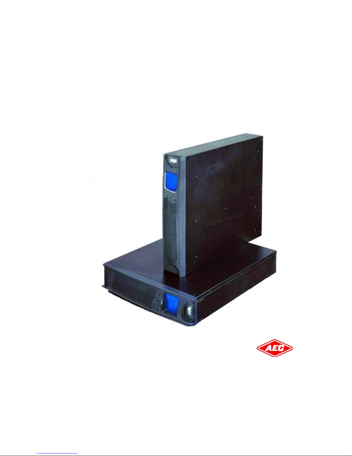
1. Presentation.............................................................................................................. 1
1.1 General description............................................................................................ 1
1.2 System configurations........................................................................................ 2
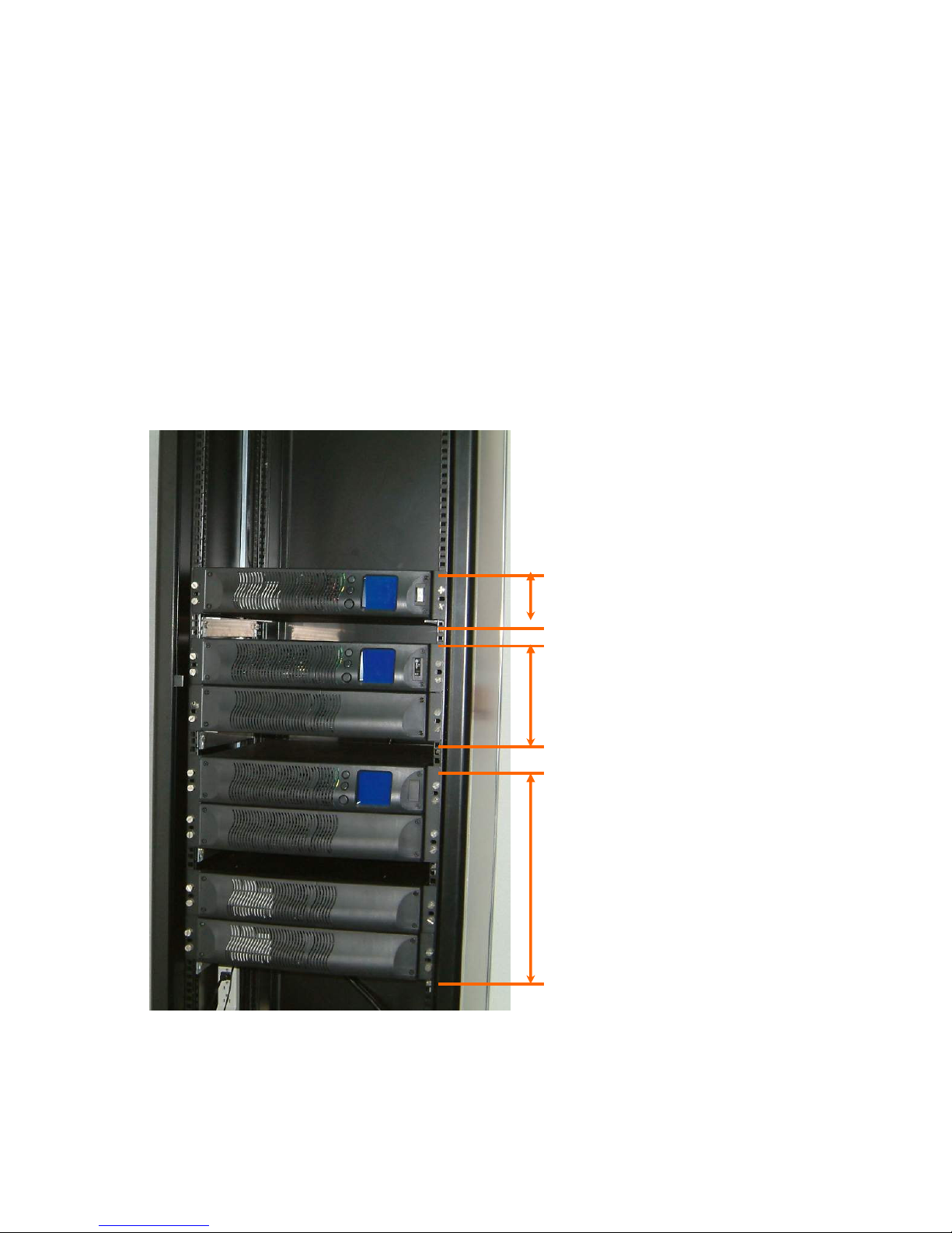
1.2.1 Rack mount............................................................................................. 2
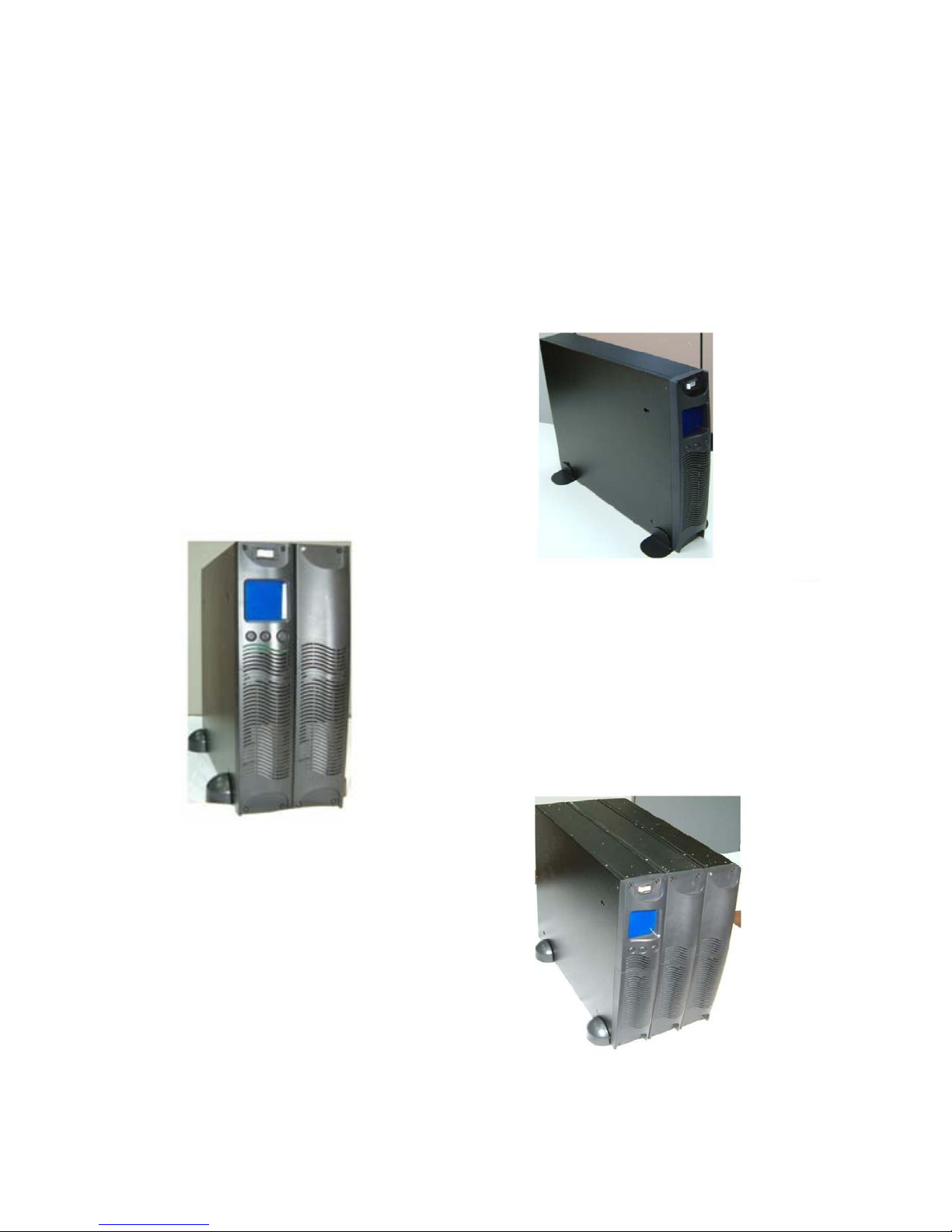
1.2.2 Tower standalone..................................................................................... 3
1.2.3 Single oltage battery design .................................................................... 4
•Battery Pack(BP) ................................................................................ 4
•Battery Modules(BM)........................................................................... 4
•Battery Modules With Charger(BMc)...................................................... 4
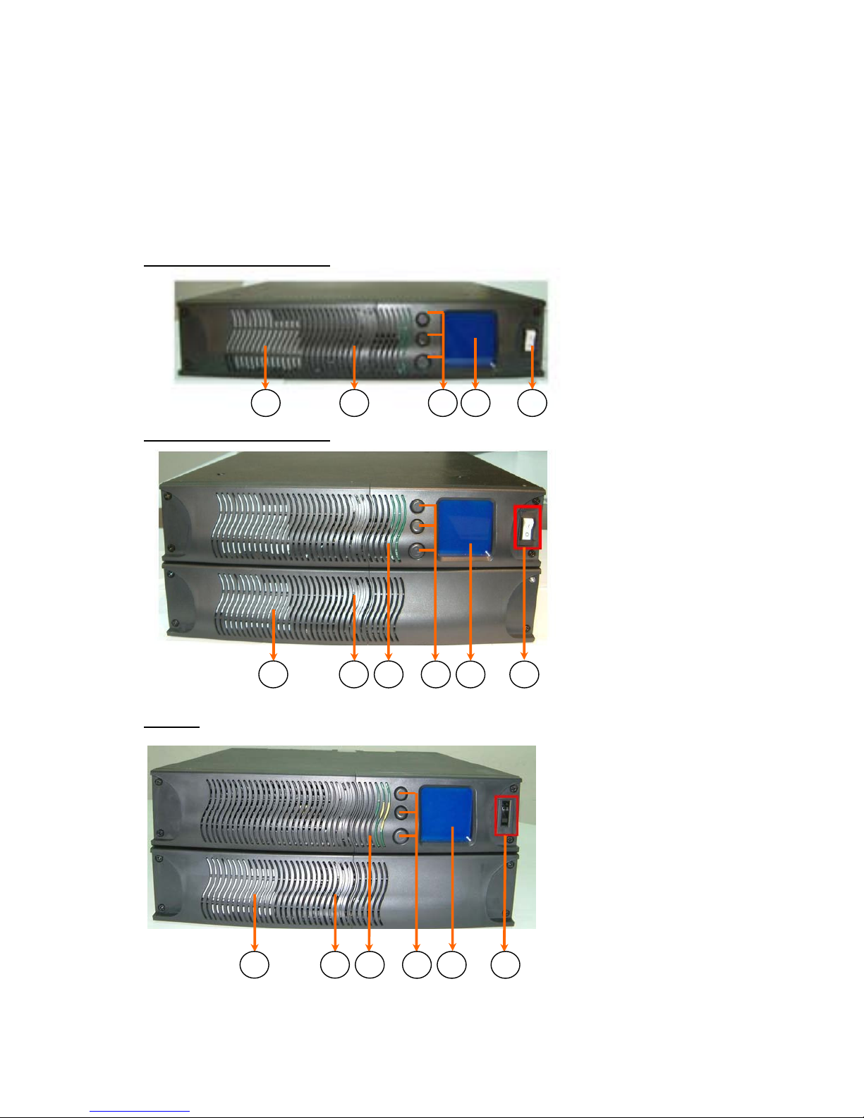
1.3 Front panel....................................................................................................... 5
1.4 Rear panel........................................................................................................ 6
•FP 1000/ FP1500/ FP 2200/ FP 3000 (UL)..................................................... 6
•FP1000/ FP1600/ FP2500/ FP3200 (CE)........................................................ 7
•Extended Battery Module............................................................................ 9
2. Installation ............................................................................................................. 10
2.1 Unpacking ...................................................................................................... 10
2.2 Installation in rack position............................................................................... 13
•Immo able ............................................................................................. 13
•Remo able ............................................................................................. 14
2.3 Installation in tower position............................................................................. 15
2.4 LCD orientation ............................................................................................... 16
2.5 Connection to communications.......................................................................... 17
2.5.1 Connection............................................................................................ 17
2.5.2 Standard .............................................................................................. 18
•RS-232............................................................................................ 18
2.5.3 Optional Interface Cards ......................................................................... 19
2.5.3.1 DB9 Dry Contact Card................................................................... 19
2.5.3.2 USB Card .................................................................................... 20
2.5.3.3 AS400 Card ................................................................................. 21
2.5.3.4 SNMP/HTTP Agent ........................................................................ 22
•USHA Pro/ USHA ProE................................................................. 22
•Net Agent Ⅱ............................................................................. 23
3. Operation ............................................................................................................... 24
3.1 Display and Controls........................................................................................ 24
3.2 Starting up/shutting down the UPS.................................................................... 26
3.3 Operating Modes ............................................................................................. 27
3.4 Configuration Settings ..................................................................................... 29
•Green Mode ............................................................................................ 29
•Output Voltage........................................................................................ 30
3.5 Cruiser Software ............................................................................................. 31
•Introduction............................................................................................ 31
•Installation ............................................................................................. 32

FP series user manual
Allis Electric Rev3. July 2005
Contents
4. Maintenance ........................................................................................................... 36
4.1 General Maintenance ....................................................................................... 36
•En ironment ........................................................................................... 36
•Storing the UPS and battery ..................................................................... 36
•When to replace the battery...................................................................... 36
4.2 Battery Pack Replacement ................................................................................ 37
4.3 Testing new batteries....................................................................................... 38
4.4 Recycling the used battery ............................................................................... 38
4.5 Fuse replacement ............................................................................................ 38
5. Troubleshooting ....................................................................................................... 39
5.1 Audible alarms and status ................................................................................ 39
5.2 Troubleshooting Guide ..................................................................................... 40
6. Appendix ................................................................................................................ 41
6.1 Technical characteristics ................................................................................... 41
•Design principle....................................................................................... 41
•Components description ........................................................................... 41
6.2 Specifications ................................................................................................. 43
•General specifications .............................................................................. 43
•Battery Run Time .................................................................................... 46
6.3 Contact information ......................................................................................... 47

FP series user manual
Allis Electric - I - Rev3. July 2005
Safety information
SAVE THESE INSTRUCTIONS. This UPS unit operates from utility power and contains a number of high
current back-up batteries, the information is important to all personnel in ol ed. Please read his manual
firs before unpacking, ins alla ion and opera ion of he UPS.
CAUTION: Safe y of persons
Opening or remo ing the co er of the unit may expose you to lethal oltage within the unit e en it is apparently
not operated and the input wiring is disconnected from electrical source.
Refer all UPS and battery ser ice to authorized ser ice personnel from the manufacture or agent authorized by
the manufacturer.
Do not dispose battery in a fire. The battery may explode.
Do not open or mutilate the battery. Release electrolyte is harmful to skin and eyes. It may be toxic.
The following precautions should be obser ed when working on batteries:
•Remo e watches, rings, and other metal objects.
•Use tools with insulated handles.
CAUTION: Produc Safe y
Install the UPS in a clean en ironment, free from moisture, flammable gases or fumes and correcti e
substances.
Keep the UPS on a flat, stable surface with adequate space around it for proper entilation.
Operate the UPS in an indoor en ironment only in an ambient temperature range of 32oF o +104oF (0oC o
+40oC).
The UPS is designed for data processing equipment. It is not intended for use with life support and other
designated “critical” de ices.
Maximum load must not exceed that shown on the UPS rating label.
Storing magnetic media on top of the UPS may result in data loss or corruption.
Once batteries ha e reached the end of their life, ensure they are disposed properly. REFER TO YOUR LOCAL
LAWS AND REGULATIONS FOR BATTERY DISPOSAL REQUIREMENTS.
The UPS must be handled with care and attention since the high energy stored within the batteries. It must
always be kept in the position marked on the external packaging and must not be dropped.
Please keep unobstructed air in the exhaust holes of UPS.
The battery should be maintained on a regular time schedule.
CAUTION: Special Precau ions
The UPS should be installed according to the instructions in this manual. Failure to do so could result in safety
issues. It could also in alidate your warranty.
DO NOT CONNECT equipment that could o erload the UPS or demand half-wa e rectification from the UPS, for
example: elec ric drills, vacuum cleaners, prin ers or hair dryers.
Adjust only those controls that are listed by the Adjustment Section. If the unit does not operate normally by
following the operating instructions, contact the sales representati es.
Icon Usage
These icons may be found in the content.
WARNING: Ob ious danger to personnel or equipment.
CAUTION: Possible danger to personnel or equipment
Impor an informa ion

FP series user manual
Allis Electric - II - Rev3. July 2005
Limited product warranty and policy
Limi ed Produc Warran y-
AEC warrants this equipment, when properly applied and operated within specified
conditions, against faulty materials or workmanship for a period of 24 months after the date
of purchase. For equipment located outside Taiwan, AEC only co ers faulty parts. AEC
products repaired or replaced pursuant to this warranty shall be warranted for the
unexpired portion of the warranty applying to the original product. This warranty applies
only to the original purchaser.
This warranty does not co er shipping costs, installation costs, maintenance and ser ice
items, calibration and adjustment. Repair or replacement of a defecti e part, or the
crediting to the user of the alue thereof, does not extend the original warranty period.
Warran y policy-
The warranty shall be oid if (a) the equipment is damaged by the customer, is improperly
used, is subjected to an ad erse operating en ironment, or is operated outside the limits of
its electrical specifications; (b) the equipment is repaired or modified by anyone other than
AEC or AEC-appro ed personnel; or (c) has been used in a manner contrary to the product’s
operating manual or other written instructions. All claims under this warranty must be
submitted in writing to AEC within 30 days of the occurrence or the claim will not be
considered. This warranty does not include damage resulting from accident or misuse.
AEC reser es the right to determine whether the damage to the connected equipment is
due to malfunction of the AEC product by requesting the equipment in question to be sent
to AEC for examination. This policy is abo e and beyond, only to the extent needed, of that
pro ided by any co erage of connected equipment pro ided by other sources, including,
but not limited to, any manufacturer's warranty and/or any extended warranties.
EXCEPT AS PROVIDED ABOVE, AEC MAKES NO WARRANTIES, EXPRESS OR IMPLIED,
INCLUDING WARRANTIES OF MERCHANTABILITY AND FITNESS FOR A PARTICULAR
PURPOSE.
EXCEPT AS PROVIDED ABOVE, IN NO EVENT WILL AEC BE LIABLE FOR DIRECT, INDIRECT,
SPECIAL, INCIDENTAL OR CONSEQUENTIAL DAMAGES ARISING OUT OF THE USE OF THIS
PRODUCT, EVEN IF ADVISED OF THE POSSIBILITY OF SUCH DAMAGE. Specifically, AEC is
not liable for any costs, such as lost profits or re enue, loss of equipment, loss of use of
equipment, loss of software, loss of data, costs of substitutes, claims by third parties or
otherwise. Co erage also does not apply to connected medical and industrial equipment.
To recei e ser ice under this warranty, you must be the original purchaser/user of the
product in question. You must obtain a Returned Material Authorization (RMA) number from
AEC. Products must be returned to AEC with transportation charges prepaid and must be
accompanied by a brief description of the problem encountered and proof of date and place
of purchase.
The policy of AEC is one of continuous impro ement. Specifications are subject to change
without notice.

FP series user manual
Allis Electric - 1 - Rev3. July 2005
1. Presentation
1.1 General descrip ion
In today’s world where power requirements are increasing, utility power quality and
reliability is decreasing. Normal e eryday routines are constantly exposed to power
problems such as power outages, sags, or surges. Any of these problems can spell disaster
for the unprepared. Down time resulting form power problems costs industries billions of
dollars o er the course of a year. Industrial and commercial end-users need to be prepared
when the power that they rely on is also a potential problem.
One way to protect critical systems from power outage and sags is the FP-series line of
true on-line uninterruptible power supplies (UPS). The FP-series UPS is designed for
optimizing power quality with the ease of installation.
The FP series Fea ures:
•Double con ersion
•Continuous battery charger and in erter for primary power path
•Constant battery connection to in erter and load
•Guaranteed full power operation during power failure
•No oltage drop and zero transfer time
•Light weight unit
•Hot-swappable battery
•User-friendly Graphic LCD
Applica ions :
•Computers
•Network Ser ers
•Workstations
•Wireless Communications
•Other Electronic Peripherals

FP series user manual
Allis Electric - 2 - Rev3. July 2005
1. Presentation
1.2 Sys em configura ions
1.2.1 Rack moun
2U (426 W ×
××
× 88 H ×
××
× 500 D mm)
4U (426 W ×
××
× 176 H ×
××
× 500 D mm)
8U (426 W ×
××
× 352 H ×
××
× 500 D mm)

FP series user manual
Allis Electric - 3 - Rev3. July 2005
1. Presentation
1.2.2 Tower s andalone
2U (88 W×
××
× 426 H ×
××
× 500 D mm)
4U (176 W×
××
× 426 H ×
××
× 500 D mm)
6U (264 W×
××
× 426 H ×
××
× 500 D mm)

FP series user manual
Allis Electric - 4 - Rev3. July 2005
1. Presentation
1.2.3 Single vol age ba ery design
Ba ery Pack(BP)
The 48VDC standard battery pack contains four 4 × 12V7AH
lead-sealed acid batteries. It is used in all FP series UPS models and
is interchangeable with each other.
Ba ery Modules(BM)
The battery module contains two(2) Battery Packs. The standard 2U
high single module design always for easy configuration when adding
extra battery modules for extended backup times.
Ba ery Modules Wi h Charger(BMc)
The BMc is a BM with an added battery charger. The charger shortens
the recharge time of the batteries.
Additional battery charger

FP series user manual
Allis Electric - 5 - Rev3. July 2005
1. Presentation
1.3 Fron panel
FP1000/FP1500/FP1600
1. Vent
2. Push Buttons
3. Graphic LCD Display
4. Input Breaker Switch
•FP1000: 15A 125V (UL) or
10A 250V (CE)
•FP1500: 15A 125V (UL)
•FP1600: 10A 250V (CE)
5. Internal 48VDC Battery Pack
FP2200/FP2500/FP3200
1. Vent
2. Push Buttons
3. Graphic LCD Display
4. Input Breaker Switch
•FP2200: 20A 125V (UL)
•FP2500: 15A 250V (CE)
•FP3200: 20A 250V (CE)
5. 2U 96VDC Battery Module
FP3000
1. Vent
2. Push Buttons
3. Graphic LCD Display
4. Input Breaker Switch
• FP3000: 30A 125V (UL)
5. 2U 96VDC Battery Module
5
1
2
3
4
5
1
1
2
3
4
5
1
1
2
3
4

FP series user manual
Allis Electric - 6 - Rev3. July 2005
1. Presentation
1.4 Rear panel
FP 1000/ FP1500/ FP 2200/ FP 3000 (UL)
FP1000/FP1500
8
1 2 2 3 4 5 6 7
1. Input Receptacle (15A 125V) 5. Battery Connector
2. Fan 6. Output Fuse (15A 250V)
3. Optional Communication Slot 7. Output Receptacle (NEMA 5-15R)
4. Standard RS232 8. Input cable 6’ (10A 250V)
FP2200
1 2 3 4 5 6 7
1. Power Cord 6’ (NEMA 5-20P; 20A 125V) 5. Standard RS232
2. Output Fuse (15A 250V) 6. Fan
3. Output Receptacles (NEMA (1)5-15R; (2)5-20R) 7. Battery Connector
4. Optional Communications Slot

FP series user manual
Allis Electric - 7 - Rev3. July 2005
1. Presentation
FP3000
1 2 3 4 5 6 7 8 9
1. Power Cord 6’ (NEMA L5-30P; 30A 125V) 6. Battery Circuit Breaker
2. Output Fuse (15A 250V) 7. Fan
3. Output Receptacles (NEMA (1)5-15R; (1)L5-30R) 8. Battery Connector
4. Optional Communications Slot 9. Battery Cable
5. Standard RS232
FP1000/ FP1600/ FP2500/ FP3200 (CE)
FP1000/ FP1600
Australian
8
British
8
French &
German
1 2 3 4 5 6 7
1. Input Receptacle (10A 250V) 5. Battery Connector
2. Fan 6. Output Fuse (10A 250V)
3. Optional Communications Slot 7. Output Receptacle (refer to )
4. Standard RS232 8. Input cable 6’ (10A 250V)
8

FP series user manual
Allis Electric - 8 - Rev3. July 2005
1. Presentation
1.IEC TYPE
2. EUROPE TYPE
FRENCH BRITISH GERMAN AUSTRALIAN
FP2500/ FP3200
Australian
10
British
10
French &
German
10
1 2 3 4 5 6 7 8 9
1. Input Receptacle (15A 250V) 6. Battery Circuit Breaker
2. Output Fuse (15A 250A) 7. Fan
3. Output Receptacles (refer to ) 8. Battery Connector
4. Optional Communication Slot 9. Battery Cable
5. Standard RS232 10. Input Cable 6’ (16A 250V)
1.IEC TYPE
2. EUROPE TYPE
FRENCH BRITISH GERMAN AUSTRALIAN
Ou pu Recep acle op ions for FP1000/ FP1600.
Ou pu recep acle op ions for FP2500/ FP 3200.

FP series user manual
Allis Electric - 9 - Rev3. July 2005
1. Presentation
Ex ended Ba ery Module
How o plug in he ba ery connec or ?
Before plugging in ba ery connec or, please make sure he UPS uni is off.
This is a cri ical ac ion o ensure he safe y of he ins aller.
How o add on he addi ional BM or BMc ?
1 3 2
1. Battery Connector
2. Standard Battery Cable
3. Additional Battery Cable

FP series user manual
Allis Electric - 10 - Rev3. July 2005
2. Installation
2.1 Unpacking
The FP-Series UPS can be supplied in a number of boxes depending upon the model ordered.
The number of boxes should be as follows:
MODEL (Box 1) BATTERY MODULE (Box 2) TOTAL BOXES
FP1000/FP1500/FP1600 N/A (internal battery pack) 1 Box
FP2200/FP2500/FP3000/FP3200 1 Battery Module 2 Boxes
The UPS and i s shipping box are bo h labeled wi h he same bar code and
serial number. If he UPS has a problem, hen please have he
informa ion on he label ready and con ac your sales represen a ive.

FP series user manual
Allis Electric - 11 - Rev3. July 2005
2. Installation
FP1000/FP1500/FP1600
Shipping Box
1 2 3
4 5 6
Mounting- feet × 2 Rack-mount × 2
7
Shipping Box Includes:
1. UPS
2. RS-232 communica ions cable
3. Cruiser sof ware ins alla ion CD
4. User Manual (CD)
5. 2pcs moun ing-fee for ower configura ion
6. 2pcs 19” rack ears (+screws) for rack-moun configura ion
7. Power Cord (for FP1000/FP1500/FP1600 only)

FP series user manual
Allis Electric - 12 - Rev3. July 2005
2. Installation
FP 2200/FP2500/FP3000/FP3200
Box 1
(Please refer to Shipping Box contents included in
FP1000/FP1500/FP1600 pre ious page)
Box 2
2 3 4 5
1
Box 2 Includes:
1. BM (or BMc)
2. 2pcs Ex ension link for ower configura ion
3. 2pcs 19” rack ears (+screws) for rack-moun configura ion
4. A s eel link o connec he UPS and BM (or BMc)
5. Ba ery cable

FP series user manual
Allis Electric - 13 - Rev3. July 2005
2. Installation
2.2 Ins alla ion in rack posi ion
Immovable
1. Align the mounting ears and secure with the supplied
screws.
2. Slide the UPS or battery module onto the fixed mounting
rails.
3. Secure the mounting ears to the posts.
4. Repeat the abo e steps for each UPS and battery module
until installation is complete.
The rack-
moun ears WILL NOT suppor he
weigh of he UPS nor he ba ery module
.
They are used for moun ing he UPS
and
ba ery module
on o he rack. Moun ing rails
are required for each UPS or ba ery module. If
rails are no ins alled on he rack, hen
please
con ac
your service represen a ive o order a
rail ki .

FP series user manual
Allis Electric - 14 - Rev3. July 2005
2. Installation
Removable
Optional slide rails are a ailable. Please contact your sales representati e for more details.
1. Align the mounting ears and secure with the supplied screws.
2. Fasten the inner parts of the slide rails to the UPS or battery
module with the screws pro ided.
3. Secure slide rails to posts. As a precaution , fixed mounting rails
should be installation below the slide rails.
4. Slide the UPS or battery module into the slide rails.
5. Repeat the abo e steps for each UPS and battery module until
installation is complete.

FP series user manual
Allis Electric - 15 - Rev3. July 2005
2. Installation
2.3 Ins alla ion in ower posi ion
The mounting feet feature as flexibility in configuration and are able to add on the other Battery
module using extendible links to meet long runtimes requirement.
(3) (4) (5)
(2) (3) (4)
(1) (2) (3)
(1) (2)
(1)
This manual suits for next models
6
Table of contents
Other AEC UPS manuals
Popular UPS manuals by other brands

Simpex Electronic
Simpex Electronic MEAN WELL DR-UPS40 installation manual

ION
ION ION 30ACi+ Operation manual

Vertiv
Vertiv Liebert GXT4-6000RTL630 Installer/user guide

Eaton
Eaton Powerware 9390 Installation and operation manual

CyberPower
CyberPower UPS BR850ELCD user manual

Minuteman
Minuteman Continuous Power Series owner's manual

Huawei
Huawei UPS5000-E Series quick guide

ABB
ABB PowerValue 11 RT quick guide

MGE UPS Systems
MGE UPS Systems Pulsar M 3000 RT 3U XL Installation and user manual

Altronix
Altronix ReServ Series installation guide

Cyber Power
Cyber Power BR1200ELCD quick start guide

Eaton
Eaton 9395-275 User and installation guide