Siemens Nixdorf D1042 User manual


Sie haben ...
... technische Fragen oder Probleme?
Wenden Sie sich bitte an:
• unsere Hotline:
Mo-Fr: 9 - 18 Uhr
Sa: 9 - 14 Uhr
Tel.: ++49 (0) 180 3777 000
• einen unserer IT-Service Shops
• Ihren zuständigen Vertriebspartner
• Ihre Verkaufsstelle
Die Adressen Ihrer Servicepartner
finden Sie im Garantieheft oder im
Service-Adressenheft.
Aktuelle Informationen zu unseren
Produkten, Tips, Updates usw. finden
Sie im Internet:
http://www.siemensnixdorf.com/pc
... uns zu diesem Handbuch etwas
mitzuteilen?
Schicken Sie uns bitte Ihre Anregungen
unter Angabe der Bestellnummer dieses
Handbuches.
Siemens Nixdorf Informationssysteme AG
Redaktion OEC BS2 OS ID4
Otto-Hahn-Ring 6
D-81730 München
Is there ...
... any technical problem or other
question you need clarified?
Please contact:
• one of our IT Service Shops
• your sales partner
• your sales office
The addresses of our IT Service
Shops can be found in the guarantee
coupon booklet.
The latest information on our
products, tips, updates, etc., can be
found on the Internet under:
http://siemensnixdorf.com/pc
... anything you want to tell us
about this manual?
Please send us your comments quoting
the order number of the manual.
Siemens Nixdorf Informationssysteme AG
User Documentation Department,
OEC BS2 OS ID 4
Otto-Hahn-Ring 6
D-81730 München

Noch Fragen zur Weiterbildung?
Das Siemens Nixdorf Training Center bietet Weiterbildungsberatung, Kurse und
Selbstlernmedien zu fast allen Themen der Informationstechnik an - bei Ihnen
vor Ort oder in einem Training Center in Ihrer Nähe, auch international.
Nennen Sie uns Ihren Trainingsbedarf oder fordern Sie Informationen an -
am schnellsten geht es per Fax: (089) 636-42945
Oder schreiben Sie an:
Siemens Nixdorf Informationssysteme AG
Training Center, Beratungsservice
D-81730 München
Your training needs?
The Siemens Nixdorf Training Centers offer you a wide range of training courses
in information technology and on IT products and other subjects - onsite near to
your workplace or offsite at one of our training centers.
Contact us for information on consulting, course schedules and selfstudy material -
Either fax (which is the fastest way):
Fax: ..49 89 636-42945
Or write to:
Siemens Nixdorf Informationssysteme AG
Training Center, Beratungsservice
D-81730 München
! "
# $
%&
' () * +,
--./0
123-. 45
6(&7 (8
9 ,
+, .:/1 .:&/1
A26361-D1042-Z120-1-7419

System board D1042
System board D1042
Technical Manual
Technical Manual
Deutsch
En
g
lish
Ausgabe Juni 1998
June 1998 edition

Creative ist ein eingetragenes Warenzeichen, Sound Blaster 16 und VIBRA 16C sind
Warenzeichen der Creative Technology Ltd.
Intel und Pentium sind eingetragene Warenzeichen und MMX und OverDrive sind
Warenzeichen der Intel Corporation, USA.
AMD-K6 ist ein Warenzeichen der Advanced Micro Devices, Inc.
Microsoft, MS, MS-DOS und Windows sind eingetragene Warenzeichen der Microsoft
Corporation.
PS/2 und OS/2 Warp sind eingetragene Warenzeichen von International Business Machines,
Inc.
Alle weiteren genannten Warenzeichen sind Warenzeichen oder eingetragene Warenzeichen
der jeweiligen Inhaber und werden als geschützt anerkannt.
Copyright Siemens Nixdorf Informationssysteme AG 1998.
Alle Rechte vorbehalten, insbesondere (auch auszugsweise) die der Übersetzung, des
Nachdrucks, der Wiedergabe durch Kopieren oder ähnliche Verfahren.
Zuwiderhandlungen verpflichten zu Schadenersatz.
Alle Rechte vorbehalten, insbesondere für den Fall der Patenterteilung oder GM-Eintragung.
Liefermöglichkeiten und technische Änderungen vorbehalten.
Creative is a registered trademark, Sound Blaster 16 and VIBRA 16C are trademarks of
Technology Ltd.
Intel and Pentium are registered trademarks and MMX and OverDrive are trademarks of Intel
Corporation, USA.
AMD-K6 is a trademark of Advanced Micro Devices, Inc.
Microsoft, MS, MS-DOS and Windows are registered trademarks of Microsoft Corporation.
PS/2 and OS/2 Warp are registered trademarks of International Business Machines, Inc.
All other trademarks referenced are trademarks or registered trademarks of their respective
owners, whose protected rights are acknowledged.
Copyright Siemens Nixdorf Informationssysteme AG 1998.
All rights, including rights of translation, reproduction by printing, copying or similar methods,
even of parts are reserved.
Offenders will be liable for damages.
All rights, including rights created by patent grant or registration of a utility model or design,
are reserved.
Delivery subject to availability. Right of technical modification reserved.

A26361-D1042-Z120-5-7419 English
Contents
Introduction..............................................................................................................1
Notational conventions.....................................................................................1
Important notes........................................................................................................2
Features...................................................................................................................4
Interfaces and connectors................................................................................6
Possible screen resolution................................................................................8
Resource table ...............................................................................................10
Settings with switch block......................................................................................11
Clock speed - switch 1, 2, 3 and 4..................................................................12
Recovering System BIOS - switch 5...............................................................12
Write-protection for floppy disk drive - switch 8..............................................12
Add-on modules.....................................................................................................13
Upgrading main memory ................................................................................15
Replacing the processor.................................................................................16
Setting the processor core voltage.................................................................16
Upgrading the video memory .........................................................................17
Upgrading the wavetable module...................................................................17
Replacing the lithium battery ..........................................................................18


A26361-D1042-Z120-5-7419 English - 1
Introduction
This description applies for the System board D1042 with PCI bus (Peripheral
Component Interconnect).
iThis system board is available in different configuration levels. Depending
on the hardware configuration of your device, it may be that you cannot
find several options in your version of the system board, even though
they are described.
You may find further information in the description "BIOS Setup".
Further information to drivers is provided in the readme files on hard disk or on the
supplied drivers diskettes or on the "Drivers & Utility" CD.
Notational conventions
The meanings of the symbols and fonts used in this manual are as follows:
!Pay particular attention to texts marked with this symbol. Failure to
observe this warning endangers your life, destroys the system, or may
lead to loss of data.
iThis symbol is followed by supplementary information, remarks and tips.
Texts which follow this symbol describe activities that must be performed in the
order shown.
This symbol means that you must enter a blank space at this point.
This symbol means that you must press the Enter key.
Texts in this typeface are screen outputs from the PC.
Texts in this bold typeface are the entries you make via the keyboard.
Texts in italics indicate commands or menu item.
"Quotation marks" indicate names of chapters and terms that are being
emphasized.

Important notes
2 - English A26361-D1042-Z120-5-7419
Important notes
Store this technical manual close to the device. If you pass on the device to third
parties, you should also pass on the Operating Manual.
!Be sure to read this page carefully and note the information before you
open the PC.
Please note the information provided in the chapter "Safety" in the
Operating Manual of the PC.
Incorrect replacement of the lithium battery may lead to a risk of
explosion. It is therefore essential to observe the instructions in the
chapter „Add-on modules“ - „Replacing the lithium battery“.
The lithium battery must be replaced with an identical battery or a battery
type recommended by the manufacturer (CR2032).
Do not throw lithium batteries into the trashcan. It must be disposed of in
accordance with local regulations concerning special waste.
The shipped version of this board complies with the requirements
of the EEC directive 89/336/EEC with regard to "Electromagnetic
compatibility".
Compliance was tested in a typical PC configuration.
When installing the board, refer to the specific installation
information in the operating manual or technical manual of the
receiving device.
Connecting cable for peripherals must be adequately insulated to avoid
interference.
!Modules can become very hot during operation. Make sure you do not
touch modules when adding components to the system board. There is a
danger of burns!
iThe warranty expires if the device is damaged during the installation or
replacement of system expansions. Information on which system
expansions you can use is available from your sales office or the
customer service.

Important notes
A26361-D1042-Z120-5-7419 English - 3
Boards with electrostatic sensitive devices (ESD) may be identified by labels.
When you handle boards fitted with ESDs, you must observe the following points
under all circumstances:
• You must always discharge yourself (e.g. by touching a grounded object)
before working.
• The equipment and tools you use must be free of static charges.
• Pull out the power plug before inserting or pulling out boards containing
ESDs.
• Always hold boards with ESDs by their edges.
• Never touch pins or conductors on boards fitted with ESDs.

Features
4 - English A26361-D1042-Z120-5-7419
Features
• ATX system board
• 64-bit microprocessor Intel Pentium with MMX, with 32 Kbytes internal cache
(first-Level Cache, 16 Kbytes data cache, 16 Kbytes address cache) or
OverDrive-Processor for Pentium
or
• Prepared for AMD-K6
• The system board supports Pentium MMX™.
• 512 Kbyte Second Level Cache
• Memory configuration on the system board: 8 to 256 Mbyte (SDRAM)
• 2 Mbit Flash BIOS
• PCI bus
• IDE hard disk controller connected to PCI bus for up to four IDE drives
(e.g. IDE hard disk drives, ATAPI CD-ROM drives), (prepared for ultra DMA33
mode), supports PIO modes 0-4
• Supports booting from a 120 Mbyte floppy disk drive
• Floppy disk controller (up to 2.88 Mbytes format)
• Real-time clock/calendar with integrated battery backup
• Parallel interface (ECP- and EPP-compatible)
• 1 serial port (16C550 compatible with FIFO)
• PS/2 mouse port
• PS/2 keyboard port
• Security functions
• USB (Universal Serial Bus)
• Energy saving functions
• Loudspeaker
• Connector for remote-on (fax/modem board), chipcard reader and infrared
interface

Features
A26361-D1042-Z120-5-7419 English - 5
Optional Components
• Monitor port
• 64 bit screen controller connected to PCI bus, graphics processor
Matrox MAG 1064SG (Mystique) with Windows accelerator, 3D accelerator
and 2 Mbyte SGRAM video memory
• Video memory can be upgraded to 4 or 8 Mbytes of SGRAM (original Matrox
memory upgrade)
• Audio controller on ISA-BUS (PnP) Crystal CS 4235 Audio Codec or CS 4236
Audio Codec, 16 bit stereo; compatible with Soundblaster Pro™, Windows
Sound System and MPU 401; 3D audio support (only for CS4235); internal
FM synthesis
iThe audio output can be set in the BIOS Setup in the screen
A
dvanced/Peripheral Configuration, menu option Audio Output to Line Level
or Amplifier Level. Use Line Level if you connect headphones or an active
loudspeaker (with amplifier) to the audio output. Use Amplifier Level if you
use passive loudspeakers.
• Connector for feature connector
• Connector for CD-line in, Game/Midi, Voice-Modem, AUX IN
• Microphone jack
• Audio input (Line in)
• Connector for headphones or active speakers
• Connector for Wake On LAN (WOL)
• I2C connector
• Prepared for Siemens Nixdorf system monitoring
Features
6 - English A26361-D1042-Z120-5-7419
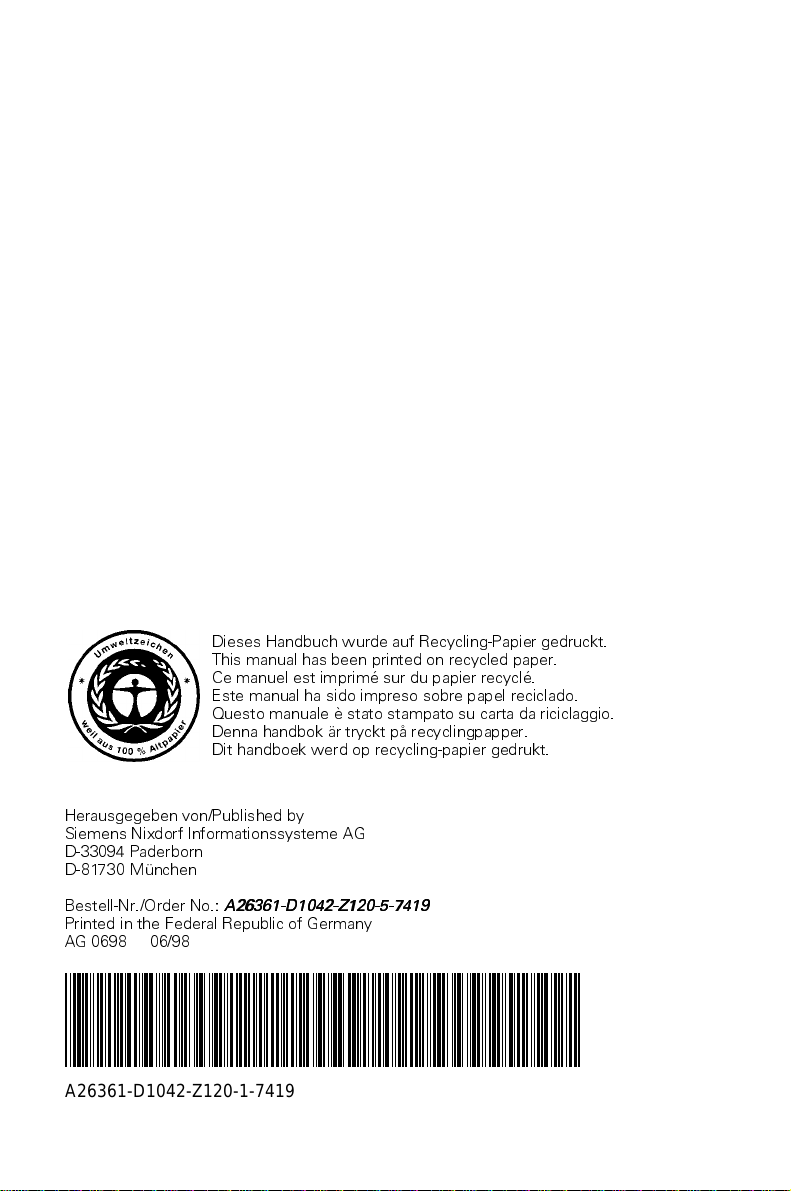
Interfaces and connectors
1
2
3
4
567
8
1/2
3
4
5
6
7/8
1 = Audio connector
2 = MIDI/Game port
3 = Monitor port
4 = Parallel port
5 = Serial port 1
6 = USB ports
7 = PS/2 keyboard port
8 = PS/2 mouse port
The connectors marked do not have to be present on the system board.
Features
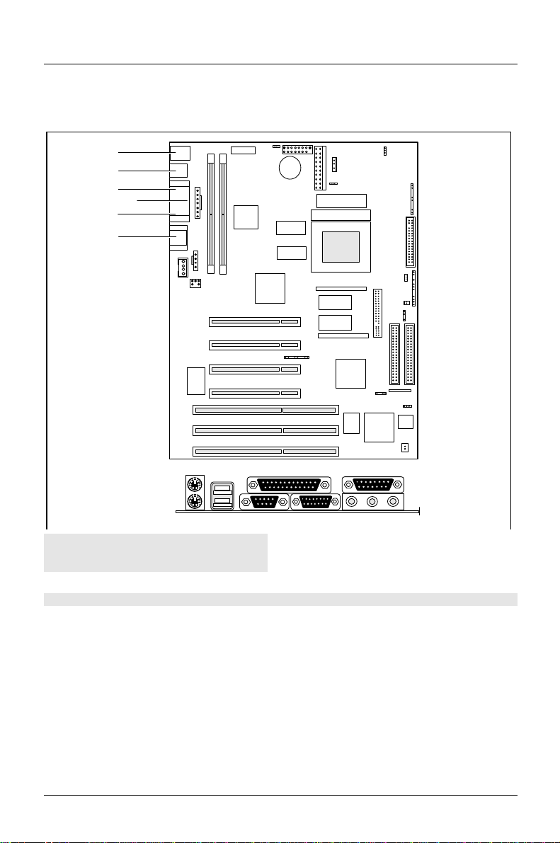
A26361-D1042-Z120-5-7419 English - 7
1
2
345
6
7
8
9
10
11
12
13
14
15
16
17
18
19
20
21 22
1 = Cover detection
2 = Intrusion connector
3 = Connector for chipcard reader
4 = Power supply 1
5 = Fan
6 = Power supply 2
7 = Connector 2 for control panel
8 = Floppy disk drive
9 = SCSI indicator
10 = Connector 1 for control panel
11 = ON/OFF button
12 = Feature connector
13 = IrDA
14 = IDE drives 1 and 2 (primary)
15 = IDE drives 3 and 4 (secondary)
16 = I2C connector
17 = Loudspeaker
18 = Wake On LAN (WOL)
19 = Connector for fax boards
20 = Voice modem
21 = AUX IN
22 = CD Line in
The connectors marked do not have to be present on the system board.

Features
8 - English A26361-D1042-Z120-5-7419
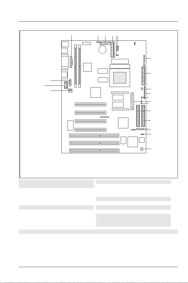
Possible screen resolution
Depending on the operating system used the screen resolutions in the following
table refer to the screen controller on the system board. If you are using an
external screen controller, you will find details of supported screen resolutions in
the Operating Manual or Technical Manual supplied with the controller.
To select the appropriate setting for your monitor, please use the
Matrox VGA drivers supplied.
In Windows 95 you can select your monitor type (you should possibly use the
standard type) and the resolution in the Control Panel under Display Properties in
the tabs MGA-Monitor and MGA settings after these drivers have been installed.
Screen
resolution Refresh
rate (Hz) Horizontal-
rate (kHz) Max. number
of colors
(2MB)
Max. number of
colors (4MB / 8MB)
640x480 120 31 to 51 256 256
640x480 120 31 to 51 64 K 64 K
640x480 120 31 to 51 16 mio. 16 mio.
800x600 120 37 to 77 256 256
800x600 120 37 to 77 64 K 64 K
800x600 120 37 to 77 16 mio. 16 mio.
1024x768 120 48 to 98 256 256
1024x768 120 48 to 98 64 K 64 K
1024x768 120 48 to 98 - - 16 mio.
1152x864 110 57 to 100 256 256
1152x864 110 57 to 100 64 K 64 K
1152x864 110 57 to 100 - - 16 mio.
1280x1024 100 62 to 107 256 256
1280x1024 100 62 to 107 - - 64 K
1280x1024 100 62 to 107 - - 16 mio.
- - Not available; * : this value is only available with 8 MB.
64 K: high color (16 bit); 16 million: true color (24 bit)

Features
A26361-D1042-Z120-5-7419 English - 9
Screen
resolution Refresh
rate (Hz) Horizontal-
rate (kHz) Max. number
of colors
(2MB)
Max. number of
colors (4MB / 8MB)
1600x1024 90 71 to 96 256 256
1600x1024 90 71 to 96 - - 64K
1600x1024 89 71 to 96 - - 16 mio.*
1600x1200 84 71 to 105 256 256
1600x1200 84 71 to 105 - - 64 K
1600x1200 75 71 to 105 - - 16 mio.*
1600x1280 75 94 to 100 256 256
1600x1280 75 94 to 100 - - 64 K
1600x1280 72 94 to 100 - - 16 mio.*
- - Not available; * : this value is only available with 8 MB.
64 K: high color (16 bit); 16 million: true color (24 bit)
Features
10 - English A26361-D1042-Z120-5-7419
Resource table
assigned
IRQ possible IRQ Possible
Address Possible
DMA
Keyboard IRQ1
IrDA / chip card reader IRQ3 IRQ3,
IRQ4 02E8, 02F8,
03E8, 03F8
Serial interface COM1 IRQ4 IRQ4,
IRQ3 03F8, 03F8
02E8, 02E8
Floppy disk drive controller IRQ6 DMA2
Parallel interface LPT1 IRQ7 IRQ5, IRQ7 0278, 0378,
03BC DMA1, DMA3
RTC IRQ8
Audio controller
Joystick:
Base address:
MPU 401:
Adlib:
IRQ5, IRQ7,
IRQ9, IRQ11,
IRQ12, IRQ15 0200-0207
0220-022F
0240-024F
0260-026F
0280-028F
0300-0301
0330-0331
0338-038B
DMA1, DMA3,
DMA0
USB controller IRQ11
Mouse controller IRQ12
Numeric processor IRQ13
IDE controller 1 IRQ14
IDE controller 2 IRQ15
"assigned IRQ" = interrupts assigned as shipped
"Possible IRQ" = these interrupts can be used for your particular application
"Possible address" = this address can be used for your particular application
"Possible DMA" = these DMAs can be used for your particular application
iMPU 401: If you want to use external MIDI devices (for example a MIDI
keyboard), you must assign an interrupt for the MPU 401 (MIDI interface).
Detailed information is provided in the audio documentation on the driver
and utility CD.
Please note that a resource cannot be used by two applications at the
same time.

Settings with switch block
A26361-D1042-Z120-5-7419 English - 11
Settings with switch block
OFF ON
1
2345678
Switch 1, 2, 3 and 4 = clock speed
Switch 5 = write-protection for system BIOS
Switch 6 = must be set to off
Switch 7 = reserved
Switch 8 = write protection for floppy disk
drive

Settings with switch block
12 - English A26361-D1042-Z120-5-7419
Clock speed - switch 1, 2, 3 and 4
!The switches may only be set as specified in the table below for the
particular processor used.
processor switch 1 switch 2 switch 3 switch 4
166 MHz on off on on
200 MHz on off off on
233 MHz on off off off
Reserved off off off off
Recovering System BIOS - switch 5
Switch 5 enables recovery of the old system BIOS after an attempt to update has
failed. Memory bank 1 must be populated in order to be able to restore the system
BIOS. To restore the old BIOS you need a Flash BIOS Diskette (call customer
service).
on The System BIOS executes from floppy drive A: and restores the
System BIOS on the system board.
off The System BIOS is started from the system board (default setting).
Write-protection for floppy disk drive - switch 8
Switch 8 is used to define whether floppy disks can be written or deleted in the
floppy disk drive. To write and delete floppy disks, the write-protection in BIOS
setup must be disabled (in menu Security, the field Diskette Write must be set to
Enabled).
on The floppy disk drive is write-protected.
off Read, write and delete floppy disks is possible (default setting).
Other manuals for D1042
1
Table of contents
Other Siemens Nixdorf Motherboard manuals

Siemens Nixdorf
Siemens Nixdorf Fujitsu D1115 User manual

Siemens Nixdorf
Siemens Nixdorf Fujitsu D1160 User manual

Siemens Nixdorf
Siemens Nixdorf D756 User manual

Siemens Nixdorf
Siemens Nixdorf D802-C User manual

Siemens Nixdorf
Siemens Nixdorf D824 User manual

Siemens Nixdorf
Siemens Nixdorf D931 User manual

Siemens Nixdorf
Siemens Nixdorf D970 User manual

Siemens Nixdorf
Siemens Nixdorf D818 User manual

Siemens Nixdorf
Siemens Nixdorf D858 User manual

Siemens Nixdorf
Siemens Nixdorf D808 User manual


