Siemens Nixdorf D1085 User manual
A26361-D1085-Z120-4-7419 English - 1
Introduction
This Technical Manual applies for the system board D1085.
iThis system board is available in different configuration levels. Depending on the
hardware configuration of your device, it may be that you cannot find several options in
your version of the system board, even though they are described.
You may find further information in the description "BIOS Setup".
Further information to drivers is provided in the readme files on hard disk or on the supplied drivers
diskettes or on the "Drivers & Utility" or "ServerStart" CD.
Notational conventions
The meanings of the symbols and fonts used in this manual are as follows:
!Pay particular attention to texts marked with this symbol. Failure to observe this warning
endangers your life, destroys the system, or may lead to loss of data.
iThis symbol is followed by supplementary information, remarks and tips.
Texts which follow this symbol describe activities that must be performed in the order shown.
This symbol means that you must enter a blank space at this point.
This symbol means that you must press the Enter key.
Texts in this typeface are screen outputs.
Texts in this bold typeface are the entries you make via the keyboard.
Texts in italics indicate commands or menu items.
"Quotation marks" indicate names of chapters and terms that are being emphasized.

Important notes
2 - English A26361-D1085-Z120-4-7419
Important notes
Store this manual close to the device. If you pass on the device to third parties, you should also
pass on this manual.
!Be sure to read this page carefully and note the information before you open the PC.
You cannot access the components of the system board without first opening the device.
How to dismantle and reassemble the device is described in the Operating Manual
accompanying the device.
Please note the information provided in the chapter "Safety" in the Operating Manual of
the PC.
Incorrect replacement of the lithium battery may lead to a risk of explosion. It is therefore
essential to observe the instructions in the chapter "Add-on modules“ - "Replacing the
lithium battery“.
The lithium battery must be replaced with an identical battery or a battery type
recommended by the manufacturer (CR2032).
Do not throw lithium batteries into the trashcan. It must be disposed of in accordance with
local regulations concerning special waste.
The shipped version of this board complies with the requirements of the EEC
directive 89/336/EEC "Electromagnetic compatibility".
Compliance was tested in a typical PC configuration.
When installing the board, refer to the specific installation information in the
Operating Manual or Technical Manual of the receiving device.
Connecting cables for peripherals must be adequately insulated to avoid interference.
!Components can become very hot during operation. Make sure you do not touch
components when making extensions to the system board. There is a danger of burns!
iThe warranty expires if the device is damaged during the installation or replacement of
system expansions. Information on which system expansions you can use is available
from your sales office or the customer service.

Important notes
A26361-D1085-Z120-4-7419 English - 3
Boards with electrostatic sensitive devices (ESD) may be identified by labels.
When you handle boards fitted with ESDs, you must observe the following points under all
circumstances:
• You must always discharge yourself (e.g. by touching a grounded object) before working.
• The equipment and tools you use must be free of static charges.
• Pull out the power plug before inserting or pulling out boards containing ESDs.
• Always hold boards with ESDs by their edges.
• Never touch pins or conductors on boards fitted with ESDs.

Features
4 - English A26361-D1085-Z120-4-7419
Features
The components and connectors marked do not have to be present on the system board.
• System board in ATX format
• Intel Pentium II processor with 66 MHz Front Side Bus for slot 1 processor socket
or
• Intel Celeron processor with 66 MHz Front Side Bus for slot 1 processor socket
Intel Pentium II and Celeron processors support MMX technology. The size of first-level cache and
second-level cache is depending on the processor used.
• Processor cache module with SEC contact technology for Intel slot 1 processor slot (SEC =
Single Edge Contact)
• 16 to 256 Mbytes main memory (SDRAM)
• 256 to 768 Mbytes main memory (SDRAM)
• Error identification and error recognition via ECC
• Flash BIOS
• AGP slot for AGP graphics controller (AGP = Accelerated Graphics Port)
• 4 PCI slots (all with busmaster capability)
• 3 ISA slots
• IDE hard disk controller connected to PCI bus for up to four IDE drives
(e.g. IDE hard disk drives, ATAPI CD ROM drive), (ultra DMA33 mode capable)
• Real-time clock/calendar with integrated battery backup
• Floppy disk controller (up to 2.88 Mbytes format)
• Supports booting from a 120 Mbyte IDE floppy disk drive
• Parallel port (ECP- and EPP-compatible)
• 2 serial ports (16C550 compatible with FIFO)
• PS/2 mouse port
• PS/2 keyboard port
• Security functions
• USB (Universal Serial Bus)
• Energy saving functions
• Connector for chipcard reader
• Fan connector
• Connector for infrared connection
• Wakeup on LAN (WOL)
• Prepared for system monitoring
• Cover detection

Features
A26361-D1085-Z120-4-7419 English - 5
Interfaces and connectors
IS A 1
IS A 3
IS A 2
PCI2
PCI1
PCI3
PCI4
3 2 1
2
3
45 6
1
1 = Serial port 2
2 = Serial port 1
3 = PS/2 mouse port
4 = PS/2 keyboard port
5 = Parallel port
6 = USB ports

Features
6 - English A26361-D1085-Z120-4-7419
IS A 1
IS A 3
IS A 2
PCI2
PCI1
PCI3
PCI4
3 2 1
1
2
3
4
5
6
7
8
9
10
11
12
13
14
1 = System fan
2 = Chipcard reader
3 = Power supply
4 = Infrared receiver (IrDA)
5 = Device ID
6 = Power supply monitor
7 = IDE drives 3 and 4 (secondary)
8 = IDE drives 1 and 2 (primary)
9 = Floppy disk drive
10 = Processor fan
11 = Control panel
12 = Intrusion plug
13 = Power On
14 = Wake-up on LAN
The connectors marked do not have to be present on the system board.
Features
A26361-D1085-Z120-4-7419 English - 7
Resource table
assigned
IRQ possible
IRQ Possible Address
(hex) Possible
DMA
Keyboard IRQ1
IrDA / WOL /
Serial port COM2 3
403F8, 02F8
03E8, 02E8
Serial interface COM1 / Chip
card reader 3
403F8, 02F8
03E8, 02E8
Floppy disk drive controller IRQ6 2
Parallel interface LPT1 5, 7 0278, 0378 1, 3
RTC IRQ8
USB controller PnP
Mouse controller IRQ12
Numeric processor IRQ13
IDE controller 1 IRQ14 01F0-01F7
IDE controller 2 IRQ15 0170-0177
"assigned IRQ" = interrupts assigned as shipped
"Possible IRQ" = these interrupts can be used for your particular application
"Possible address" = this address can be used for your particular application
"Possible DMA" = these DMAs can be used for your particular application
PCI bus interrupts
The following table shows which PCI bus interrupts on the system board are assigned.
PCI bus slot PCI bus interrupt Component on system board:
1 A AGP slot
2B
3C
4 D USB controller

Settings with switch block
8 - English A26361-D1085-Z120-4-7419
Settings with switch block
IS A 1
IS A 3
IS A 2
PCI2
PCI1
PCI3
PCI4
3 2 1
O PEN /O FF
ON
1
234 5678
Switch 1 = must be set to off
Switch 2 = System BIOS recovery
Switch 3 = Write protection for floppy disks
Switch 4 = reserved
Switches 5 - 8 = clock frequency

Settings with switch block
A26361-D1085-Z120-4-7419 English - 9
Recovering System BIOS - switch 2
Switch 2 enables recovery of the old system BIOS after an attempt to update has failed. To restore
the old system BIOS you need a Flash BIOS Diskette (please call our customer service center).
on The System BIOS executes from floppy drive A: and restores the System BIOS on
the system board.
off The System BIOS is started from the system board (default setting).
Write protection for floppy disks - switch 3
Switch 3 is used to define whether floppy disks can be written or deleted in the floppy disk drive. To
write and delete floppy disks, the write-protection in BIOS setup must be disabled (in menu Security,
the field Diskette Write must be set to Enabled).
on The floppy disk drive is write-protected.
off Read, write and delete floppy disks is possible (default setting).
Clock speed - switch 5, 6, 7 and 8
!The switches may only be set as specified in the table below for the particular
processor used.
This system board you may use only with processors with a host bus frequency of
66 MHz. Do not use processors with a host bus frequency of 100 MHz!
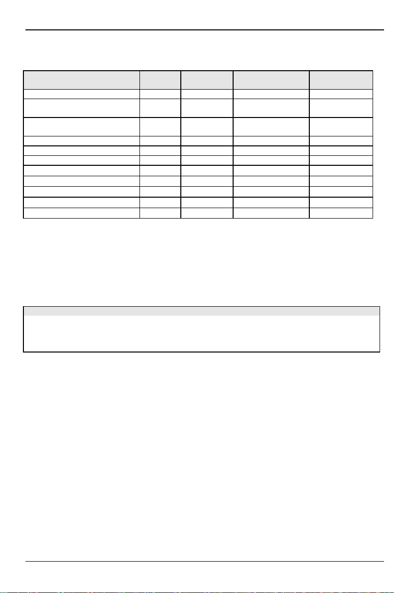
Pentium II with 66 MHz Host Bus frequency:
processor switch 5 switch 6 switch 7 switch 8
233 MHz off off on on
266 MHz on on off on
300 MHz off on off on
333 MHz on off off on
366 MHz off off off on
400 MHz on on on off

Add-on modules
10 - English A26361-D1085-Z120-4-7419
Add-on modules
IS A 1
IS A 3
IS A 2
PCI2
PCI1
PCI3
PCI4
3 2 1
12
3
4
5
7
6
1 = 2 locations for main memory (DIMM)
2 = 1 location for main memory (DIMM)
3 = 1 AGP slot
4 = 4 PCI slots
5 = 3 ISA slots
6 = Lithium battery
7 = Pentium II with heat sink
The connectors marked do not have to be present on the system board.
Add-on modules
A26361-D1085-Z120-4-7419 English - 11
Upgrading main memory
Two or three locations are available on the system board for main memory. These slots are suitable
for 16, 32, 64 and 128 Mbyte SDRAM memory modules of the DIMM format.
The board supports a maximum of 384 Mbytes when using 128 Mbyte SDRAM memory modules.
Memory modules with different memory capacities can be combined.
256 Mbyte SDRAM memory modules are possible on request. Then the board supports a maximum
of 768 Mbytes.
DIMM = Dual Inline Memory Module
SDRAM = Synchronous Dynamic Random Access Memory
!You may only use unbuffered 3.3V memory modules. Buffered memory modules
are not permitted.
SDRAM memory modules must have a cycle time of 15 ns or less or be designed
for a clock frequency of 66 MHz or higher.
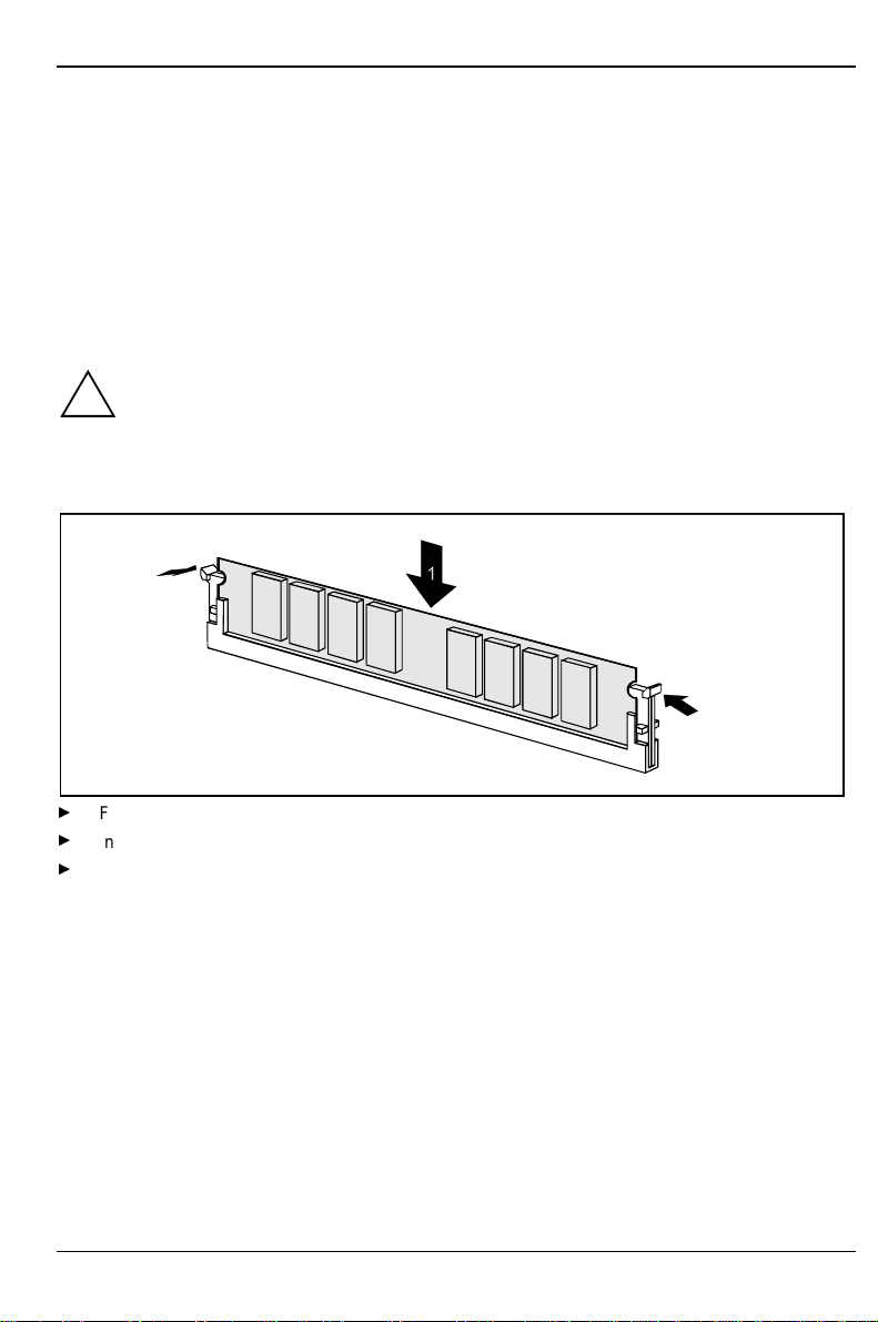
Installing memory modules
2
2
Flip the holders on each side of the relevant location outwards.
Insert the memory module into the location (1).
At the same time flip the lateral holders upwards until the memory module snaps in place (2).

Add-on modules
12 - English A26361-D1085-Z120-4-7419
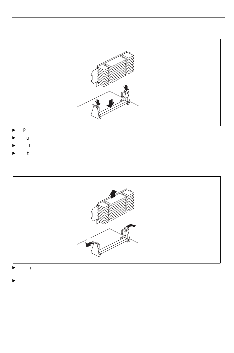
Removing a memory module
1
1
Flip the holders to the right and left of the location outwards (1).
Pull the memory module out of its location (2).

Add-on modules
A26361-D1085-Z120-4-7419 English - 13
Installing/removing the processor
Installing the Pentium II
1
1
2
2
1
Place the Pentium II in the holder (1).
Push the Pentium II down in the holder and press it into the slot until the clamps (2) to the left
and right snap into place.
Set the clock frequency of the new Pentium II using switches 5 to 8 of the switch block.
If the Pentium II has a fan, attach the associated cable to the fan connector (FAN) on the
system board.
Removing the Pentium II
If the Pentium II is equipped with a fan, then disconnect the plug-in connection of the related
cable.
Press the clamps (2) on either side of the Pentium II inwards and pull the Pentium II up and
out.
Add-on modules
14 - English A26361-D1085-Z120-4-7419
Installing the Celeron
Place the Celeron in the holder.
Push the Celeron down in the holder and press it into the slot until it snaps into place.
Set the clock frequency of the new processor using switches 5 to 8 of the switch block.
If the Celeron has a fan, attach the associated cable to the fan connector (FAN) on the system
board.
Removing the Celeron
2
1
1
If the Celeron is equipped with a fan, then disconnect the plug-in connection of the related
cable.
Press the two side holders somewhat outward while pulling the Celeron upward out of the
socket.
Add-on modules
A26361-D1085-Z120-4-7419 English - 15
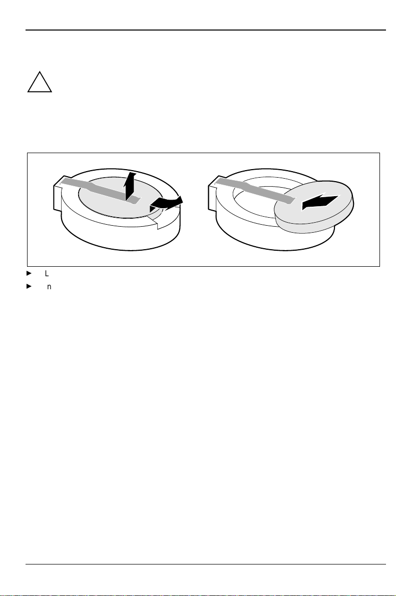
Replacing the lithium battery
!Incorrect replacement of the lithium battery may lead to a risk of explosion.
The lithium battery must be replaced with an identical battery or a battery type
recommended by the manufacturer (CR2032).
Do not throw lithium batteries into the trashcan. It must be disposed of in accordance with
local regulations concerning special waste.
Make sure that you insert the battery the right way round. The plus pole must be on the
top!
1
23
+
+++
Lift the contact (1) a few millimeters and remove the battery from its socket (2).
Insert a new lithium battery of the same type in the socket (3).


A26361-D1085-Z120-4-7419
Contents
Introduction....................................................................................................................................... 1
Notational conventions.............................................................................................................. 1
Important notes................................................................................................................................. 2
Features ........................................................................................................................................... 4
Interfaces and connectors......................................................................................................... 5
Resource table.......................................................................................................................... 7
PCI bus interrupts..................................................................................................................... 7
Settings with switch block................................................................................................................. 8
Recovering System BIOS - switch 2 ......................................................................................... 9
Write protection for floppy disks - switch 3................................................................................ 9
Clock speed - switch 5, 6, 7 and 8 ............................................................................................ 9
Add-on modules.............................................................................................................................. 10
Upgrading main memory......................................................................................................... 11
Installing/removing the processor............................................................................................ 13
Replacing the lithium battery................................................................................................... 15

A26361-D1085-Z120-4-7419
A26361-D1085-Z120-4-7419
System board D1085
Technical Manual
February 1999 edition
Intel and Pentium are registered trademarks and MMX and OverDrive are trademarks of Intel
Corporation, USA.
Microsoft, MS, MS-DOS and Windows are registered trademarks of Microsoft Corporation.
PS/2 and OS/2 Warp are registered trademarks of International Business Machines, Inc.
All other trademarks referenced are trademarks or registered trademarks of their respective owners,
whose protected rights are acknowledged.
Copyright Siemens AG 1999.
All rights, including rights of translation, reproduction by printing, copying or similar methods, even of
parts are reserved.
Offenders will be liable for damages.
All rights, including rights created by patent grant or registration of a utility model or design, are
reserved. Delivery subject to availability.
Right of technical modification reserved.
This manual suits for next models
2
Table of contents
Other Siemens Nixdorf Motherboard manuals

Siemens Nixdorf
Siemens Nixdorf Fujitsu D1160 User manual

Siemens Nixdorf
Siemens Nixdorf Fujitsu D1115 User manual

Siemens Nixdorf
Siemens Nixdorf D824 User manual

Siemens Nixdorf
Siemens Nixdorf D858 User manual

Siemens Nixdorf
Siemens Nixdorf D1025 User manual

Siemens Nixdorf
Siemens Nixdorf D808 User manual

Siemens Nixdorf
Siemens Nixdorf D1042 User manual

Siemens Nixdorf
Siemens Nixdorf D1156 User manual

Siemens Nixdorf
Siemens Nixdorf D756 User manual

Siemens Nixdorf
Siemens Nixdorf D818 User manual


