Siemens Nixdorf D1111 User manual

System board D1111
Technical Manual

Sie haben ...
... technische Fragen oder Probleme?
Wenden Sie sich bitte an:
· einen unserer IT-Service Shops
· Ihren zuständigen Vertriebspartner
· Ihre Verkaufsstelle
Die Adressen Ihrer Servicepartner finden
Sie im Garantieheft oder im Service-
Adressenheft.
Aktuelle Informationen zu unseren
Produkten, Tips, Updates usw. finden Sie
im Internet: http://www.siemens./computer
... uns zu diesem Handbuch etwas
mitzuteilen?
Schicken Sie uns bitte Ihre Anregungen unter
Angabe der Bestellnummer dieses
Handbuches.
Siemens AG
Redaktion ICP CS BS2000 OS ID4
Otto-Hahn-Ring 6
D-81730 München
Is there ...
... any technical problem or other
question you need clarified?
Please contact:
· one of our IT Service Shops
· your sales partner
· your sales office
The addresses of your service partners are
contained in the guarantee booklet or in the
service address booklet.
The latest information on our products, tips,
updates, etc., can be found on the Internet
under: http://www.siemens./computer
... anything you want to tell us
about this manual?
Please send us your comments quoting
the order number of the manual.
Siemens AG
User Documentation Department
ICP CS BS2000 OS ID4
Otto-Hahn-Ring 6
D-81730 München

Noch Fragen zur Weiterbildung?
Das Siemens Training Center bietet Weiterbildungsberatung, Kurse und Selbstlernmedien zu
fast allen Themen der Informationstechnik an - bei Ihnen
vor Ort oder in einem Training Center in Ihrer Nähe, auch international.
Nennen Sie uns Ihren Trainingsbedarf oder fordern Sie Informationen an -
am schnellsten geht es per Fax: (089) 636-42945
Oder schreiben Sie an:
Siemens AG
Training Center, Beratungsservice
D-81730 München
Your training needs?
The Siemens Training Centers offer you a wide range of training courses in information
technology and on IT products and other subjects - onsite near to your workplace or offsite at
one of our training centers.
Contact us for information on consulting, course schedules and selfstudy material -
Either fax (which is the fastest way):
Fax: ..49 89 636-42945
Or write to:
Siemens AG
Training Center, Beratungsservice
D-81730 München
Dieses Handbuch wurde auf Recycling-Papier gedruckt.
This manual has been printed on recycled paper.
Ce manuel est imprimé sur du papier recyclé.
Este manual ha sido impreso sobre papel reciclado.
Questo manuale è stato stampato su carta da riciclaggio.
Denna handbok är tryckt på recyclingpapper.
Dit handboek werd op recycling-papier gedrukt.
Herausgegeben von/Published by
Siemens AG
D-81730 München
Bestell-Nr./Order No.:
U41090-J-Z156-2-74
Printed in the Federal Republic of Germany
AG 799 7/99
U41090-J-Z156-1-74
sS
y
stem board D1111 Technical Manuall

System board D1111
(VKN: 00325.00.3.15)
Technical Manual
Deutsch
En
g
lish
Ausgabe Juli 1999
July 1999 edition

Intel ist ein eingetragenes Warenzeichen der Intel Corporation, USA.
PS/2 ist ein eingetragenes Warenzeichen von International Business Machines, Inc.
Alle weiteren genannten Warenzeichen sind Warenzeichen oder eingetragene Warenzeichen
der jeweiligen Inhaber und werden als geschützt anerkannt.
Alle Rechte vorbehalten, insbesondere (auch auszugsweise) die der Übersetzung, des
Nachdrucks, der Wiedergabe durch Kopieren oder ähnliche Verfahren.
Zuwiderhandlungen verpflichten zu Schadenersatz.
Alle Rechte vorbehalten, insbesondere für den Fall der Patenterteilung oder GM-Eintragung.
Liefermöglichkeiten und technische Änderungen vorbehalten.
Copyright Siemens AG 1999
Intel is a registered trademark of Intel Corporation, USA.
PS/2 is a registered trademark of International Business Machines, Inc.
All other trademarks referenced are trademarks or registered trademarks of their respective
owners, whose protected rights are acknowledged.
All rights, including rights of translation, reproduction by printing, copying or similar methods,
even of parts are reserved.
Offenders will be liable for damages.
All rights, including rights created by patent grant or registration of a utility model or design,
are reserved. Delivery subject to availability.
Right of technical modification reserved.

U41090-J-Z156-2-74
Contents
Introduction....................................................................................................................................... 1
Notational conventions.............................................................................................................. 1
Important notes................................................................................................................................. 2
Notes on installing and removing boards................................................................................... 3
Features ........................................................................................................................................... 4
Interfaces and connectors......................................................................................................... 5
ISA bus resources..................................................................................................................... 7
PCI bus resources .................................................................................................................... 7
PCI slots ........................................................................................................................... 7
Possible screen resolution........................................................................................................ 8
Settings with switches....................................................................................................................... 9
Write protection for floppy disks - switch 6................................................................................ 9
Skipping the password query - switch 7 .................................................................................... 9
Recovering System BIOS - switch 8 ......................................................................................... 9
Add-on modules.............................................................................................................................. 10
Slot sequence......................................................................................................................... 11
Upgrading main memory......................................................................................................... 11
SCSI LVD connection ............................................................................................................. 12
Replacing the lithium battery................................................................................................... 12


U41090-J-Z156-2-74 English - 1
Introduction
This Technical Manual describes the system board D1111, which can be equipped with up to four
Intel Xeon processors.
iThis system board is available in different configuration levels. Depending on the
hardware configuration of your device, it may be that you cannot find several options in
the system board, even though they are described.
You may find further information in the description "BIOS Setup".
Further information to drivers is provided in the readme files on hard disk or on the supplied drivers
diskettes or on the "Drivers & Utility" or "ServerStart" CD.
Notational conventions
The meanings of the symbols and fonts used in this manual are as follows:
!Pay particular attention to texts marked with this symbol. Failure to observe this warning
endangers your life, destroys the system, or may lead to loss of data.
iSupplementary information, remarks and tips follow this symbol.
Texts which follow this symbol describe activities that must be performed in the order shown.
This symbol means that you must enter a blank space at this point.
This symbol means that you must press the Enter key.
Texts in this typeface are screen outputs.
Texts in this bold typeface are the entries you make via the keyboard.
Texts in italics indicate commands or menu items.
"Quotation marks" indicate names of chapters and terms that are being emphasized.
Important notes
2 - English U41090-J-Z156-2-74
Important notes
!Pay attention to the information provided in the manual "Safety, Guarantee and
Ergonomics" and to the following notes. Be sure to read this page carefully and note the
information before you open the device.
• Store this manual close to the device. If you pass on the device to third parties, you should
also pass on this manual.
• You cannot access the components of the system board without first opening the device. How
to dismantle and reassemble the device is described in the Operating Manual accompanying
the device.
• Please note the information provided in the chapter "Safety" in the Operating Manual of the
device.
• Incorrect replacement of the lithium battery may lead to a risk of explosion. It is therefore
essential to observe the instructions in the chapter „Add-on modules“ - „Replacing the lithium
battery“.
• The lithium battery must be replaced with an identical battery or a battery type recommended
by the manufacturer (CR2032).
• Do not throw lithium batteries into the trashcan. It must be disposed of in accordance with local
regulations concerning special waste.
•
• Connecting cables for peripherals must be adequately insulated to avoid interference.
• Components can become very hot during operation. Make sure you do not touch components
when making extensions to the system board. There is a danger of burns!
The shipped version of this board complies with the requirements of the EEC directive
89/336/EEC "Electromagnetic compatibility".
Compliance was tested in a typical PC configuration.
When installing the board, refer to the specific installation information in the Operating
Manual or Technical Manual of the receiving device.
iThe warranty is invalidated if the device is damaged during the installation or
replacement of system expansions. Information on which system expansions you can
use is available from your sales outlet or the customer service center.

Important notes
U41090-J-Z156-2-74 English - 3
Notes on installing and removing boards
Boards with electrostatic sensitive devices (ESD) are identifiable by the
label shown.
When you handle boards fitted with ESDs, you must observe the following
points under all circumstances:
• You must always discharge yourself (e.g. by touching a grounded
object) before working.
• The equipment and tools you use must be free of static charges.
• Pull out the power plug before inserting or pulling out boards containing
ESDs.
• Always hold boards with ESDs by their edges.
• Never touch pins or conductors on boards fitted with ESDs.

Features
4 - English U41090-J-Z156-2-74
Features
The components and connectors marked do not have to be present on the system board.
• Intel Chipset 82450NX
• Pentium III Xeon with 500 MHz or higher, with 100 MHz Front Side Bus,
512 Kbyte, 1 Mbyte or 2 Mbyte second-level cache
• four processor slots for Pentium III Xeon processors
• 16 DIMM slots (EDO-RAM memory modules)
• four 64 bit hot-plug PCI slots
• two 32 bit hot-plug PCI slots
• two 32 bit PCI slots (both shared)
• two ISA slots (both shared)
• SCSI controller SYM53C896 onboard with 2 x Ultra 2 LVD/SE interfaces and with a transfer
rate of max. 80 Mbyte/s
• Cirrus GD5446 screen controller with 2 Mbyte video memory
• Intel i82558 Fast Ethernet LAN controller
• IDE hard disk controller connected to PCI bus
ultra DMA33 mode capable, supports PIO modes 0-4
• one external parallel interface (ECP- and EPP-compatible)
• four external serial ports
• one external and one internal USB port (USB = Universal Serial Bus)
• CAN bus
• two external PS/2 interfaces for keyboard and mouse
• system monitoring
Features
U41090-J-Z156-2-74 English - 5
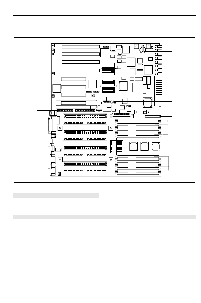
Interfaces and connectors
PCI32 Slot 2
PCI32 Slot 3
PCI32 Slot 4
PCI64 Slot 5
PCI32 Slot 1
PCI64 Slot 8
PCI64 Slot 7
PCI64 Slot 6
ISA Slot 2
ISA Slot 1
CPU 3
CPU 2
CPU 1
CPU 0
Bank A
Bank B
Bank C
Bank D
Bank A
Bank B
Bank C
Bank D
1
2
3
4
5
6
7
8
9
10
11
1 = Fax connection
2 = Lithium battery (CR2032)
3 = Wake-On LAN
4 = Voltage regulator
5 = SCSI LVD connection
6 = Memory banks A, C, B, D
7 = Memory banks A, C, B, D
8 = External ports
9 = Connector for hot plug panel
10 = IDE drive (primary)
11 = Switch block
The components and connectors marked do not have to be present on the system board.

Features
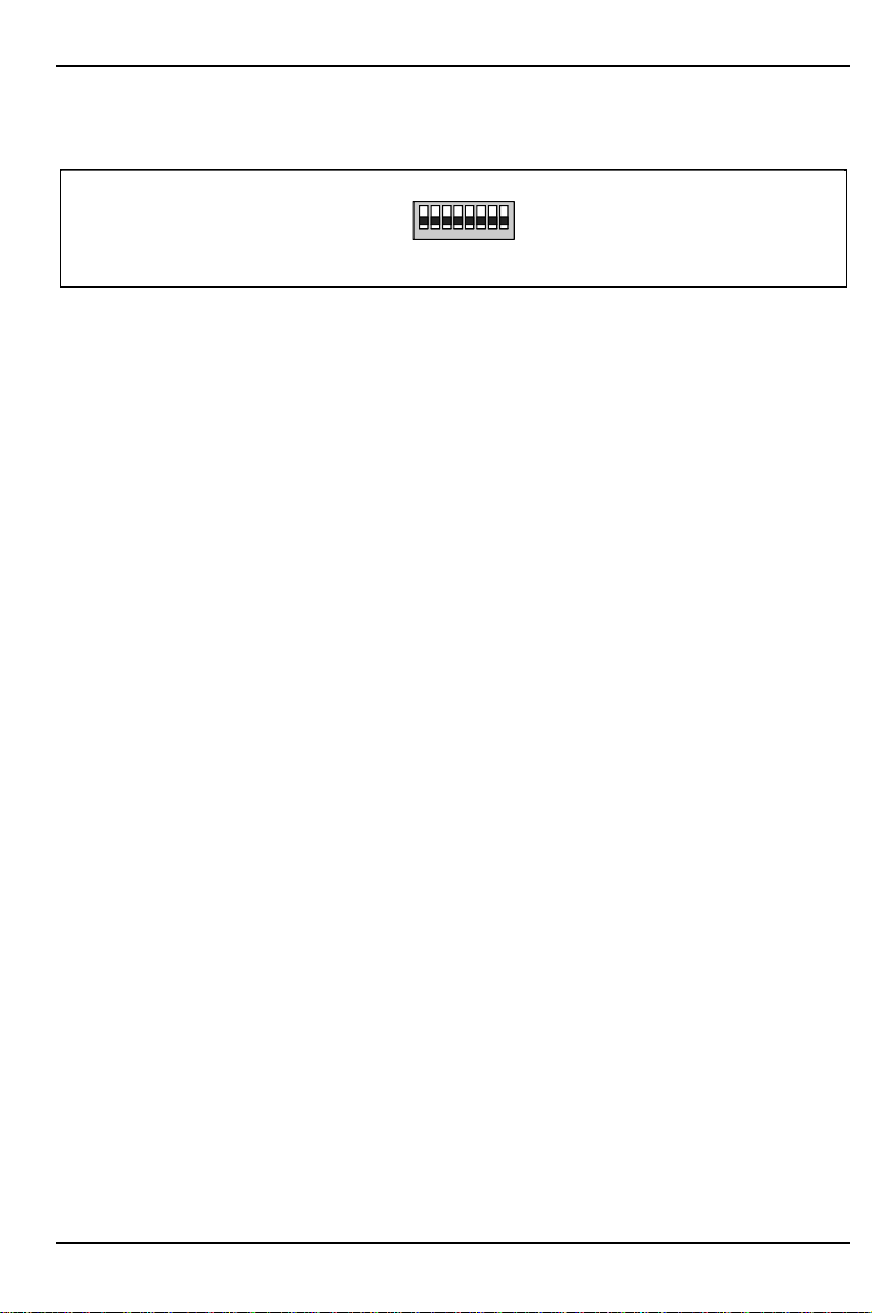
6 - English U41090-J-Z156-2-74
External ports
1234567
891011
1 = LAN port
2 = Parallel port
3 = USB port
4 = PS/2 mouse port
5 = CAN port
6 = Serial interface COM4 / Chip card reader
7 = Serial port COM2
8 = Serial interface COM1
9 = Serial port COM 3
10 = PS/2 keyboard port
11 = VGA connector
!If a chipcard reader is installed, no device may be connected to serial interface 4.
Please use the current driver from the mailbox for the chipcard reader.
Features
U41090-J-Z156-2-74 English - 7
ISA bus resources
Device IRQ Address DMA
Keyboard 1
Serial port COM2 3 03F8, 02F8, 03E8, 02E8
Serial interface COM1 4 03F8, 02F8, 03E8, 02E8
5
Floppy disk drive controller 6 2
Parallel interface LPT1 7 0278, 0378, 03BC 0, 1, 3
Real-time clock (RTC) 8
free 9, 10, 11
Mouse controller 12
Numeric processor 13
IDE controller 14 1F0-1F7
free 15
Serial port COM 3 possible: 15, 12, 11, 10, 9, 7,
6, 5, 4(shared with COM1), 3 03F8, 02F8, 03E8, 02E8
Serial port COM 4 possible: 15, 12, 11, 10, 9, 7,
6, 5, 4, 3(shared with COM2) 03F8, 02F8, 03E8, 02E8
"IRQ" = interrupt assigned as shipped
"Address" = this address can be used for your particular device
"Address" = this DMA can be used for your particular device
Default settings are shown in bold print.
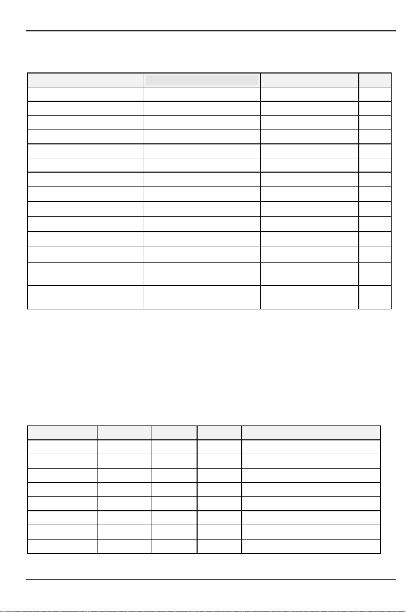
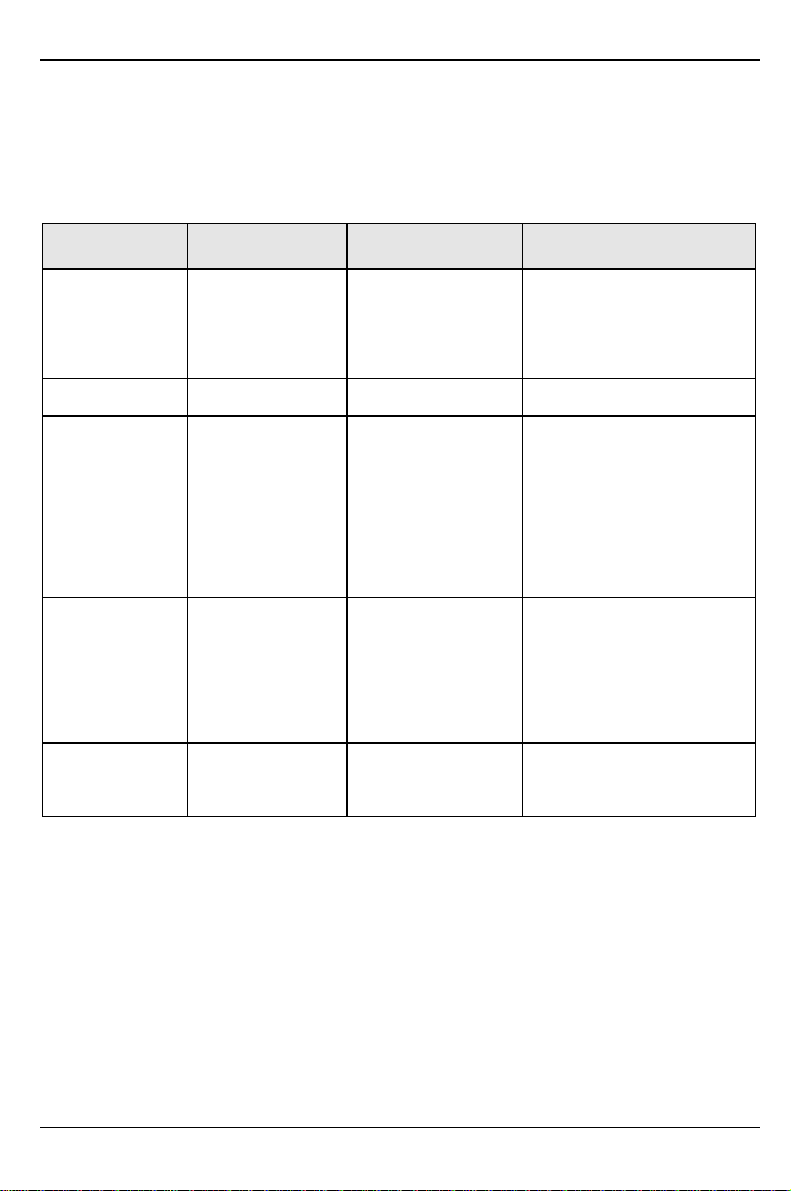
PCI bus resources
PCI slots
The following table shows an overview of the PCI slots:
PCI slot 64bit/32bit Hot plug Shared Description
1 32 bit no yes 32 bit PCI bus slot
2 32 bit no yes 32 bit PCI bus slot
3 32 bit yes no 32 bit hot-plug PCI bus slot
4 32 bit yes no 32 bit hot-plug PCI bus slot
5 64 bit yes no 64 bit hot-plug PCI bus slot
6 64 bit yes no 64 bit hot-plug PCI bus slot
7 64 bit yes no 64 bit hot-plug PCI bus slot
8 64 bit yes no 64 bit hot-plug PCI bus slot
Features
8 - English U41090-J-Z156-2-74
Possible screen resolution
Depending on the operating system used the screen resolutions in the following table refer to the
screen controller on the system board. If you are using an external screen controller, you will find
details of supported screen resolutions in the Operating Manual or Technical Manual supplied with
the controller.
Screen resolution Refresh rate (Hz) Horizontal-
rate (kHz) ** Max. number of colors
640x350 70 31,5 16
640x350 84 38 16
640x480 60 31,5 16777216
640x480 75 37,5 16777216
640x480 85 43,4 16777216
640x480 100 50,6 16777216
720x400 70 31,5 16
720x400 84 38 16
800x600 60 38 65536
800x600 60 38 16777216
800x600 72 48 65536
800x600 72 48 16777216
800x600 75 47 65536
800x600 75 47 16777216
800x600 85 53,7 65536
800x600 85 53,7 16777216
800x600 100 63 65536
800x600 100 63 16777216
1024x768 87 interlaced 36 256
1024x768 87 interlaced 36 65536
1024x768 60 48,4 256
1024x768 60 48,4 65536
1024x768 75 60 256
1024x768 75 60 65536
1024x768 85 68,7 256 *
1024x768 100 81 256 *
1280x1024 87 interlaced 49 16
1280x1024 87 interlaced 49 256
1280x1024 60 63,7 256 *
1280x1024 75 80,4 256 *
* no 16 color mode
** The horizontal rate values may have a tolerance range of ±0.3 kHz.
Settings with switches
U41090-J-Z156-2-74 English - 9
Settings with switches
OPEN / OFF
ON
12345678
Switch 1 to 5 = not used
Switch 6 = Write protection for floppy disks Switch 7 = Skipping password query
Switch 8 = Recovering system BIOS
Write protection for floppy disks - switch 6
Switch 6 is used to define whether floppy disks can be written or deleted in the floppy disk drive. To
write and delete floppy disks, the write-protection in BIOS Setup must be disabled (in menu Security,
the field Diskette Write must be set to Enabled).
on The floppy disk drive is write-protected.
off Read, write and delete floppy disks is possible (default setting).
Skipping the password query - switch 7
Switch 7 is used to define whether the password is queried at system startup, if the password
protection is enabled in BIOS Setup (in Security menu , the Password field must be set to Enabled).
onThe password query is skipped.
offThe password query is effective (default setting).
Recovering System BIOS - switch 8
Switch 8 enables recovery of the old system BIOS after an attempt to update has failed. To restore
the old system BIOS you need a Flash BIOS Diskette (please call our customer service center).
on The system boots from the "Flash BIOS floppy disk" from Drive A and reprograms
the system BIOS on the board.
off The system is started with the system BIOS from the board. The system BIOS
cannot be reprogrammed (default setting).
Add-on modules
10 - English U41090-J-Z156-2-74
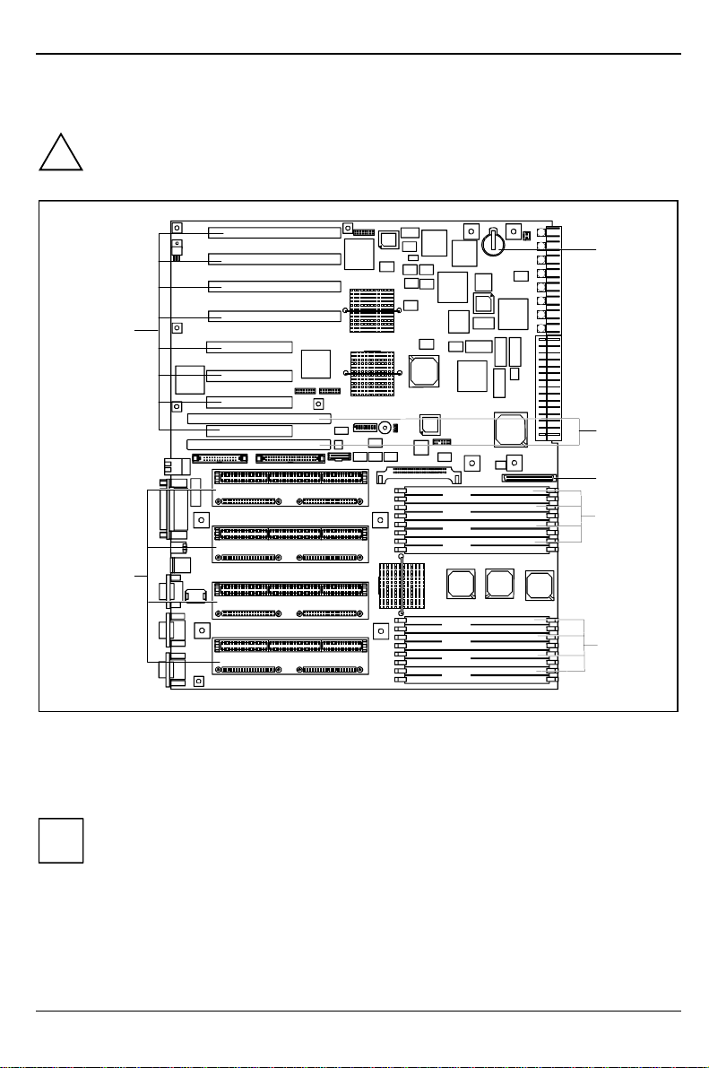
Add-on modules
!For all steps described in this chapter pull the power plug out of the power outlet!
PCI32 Slot 2
PCI32 Slot 3
PCI32 Slot 4
PCI64 Slot 5
PCI32 Slot 1
PCI64 Slot 8
PCI64 Slot 7
PCI64 Slot 6
ISA Slot 2
ISA Slot 1
CPU 3
CPU 2
CPU 1
CPU 0
Bank A
Bank B
Bank C
Bank D
Bank A
Bank B
Bank C
Bank D
1
2
3
4
5
6
7
1 = Lithium battery
2 = ISA slots 1, 2
3 = SCSI LVD connection
4 = Locations for main memory (from bottom
to top: 0A, 1A, 0C, 1C, 0B, 1B, 0D, 1D)
5 = Locations for main memory (from bottom to
top: 2A, 3A, 2C, 3C, 2B, 3B, 2D, 3D)
6 = Slots for processors
7 = PCI slots 1 to 8
iPCI slots support 3.3 V main and auxiliary voltages.
Add-on modules
U41090-J-Z156-2-74 English - 11
Slot sequence
• An additional screen controller, e.g. Matrox Millennium II PCI, must be inserted into slot 1.
• 64 bit adapters should be inserted into 64 bit slots. Slots 6 and 7 must be used first.
Upgrading main memory
These slots are suitable for 32, 64, 128 and 256 Mbyte EDO-RAM memory modules of the DIMM
format. The organization in four memory banks A to D enables fast memory access with four-fold
interleave. The board supports a maximum of 4 Gbytes.
Four identical memory modules must be installed per memory bank. Partial equipping of a memory
bank is not possible. The equipping sequence of the memory banks is arbitrary.
Every slot has a unique address (e.g. 2B). The letter specifies the memory bank to which the slot
belongs, while the digit specifies the number of the slot within the memory bank. 2B therefore
designates slot 2 in memory bank B.
DIMM = Dual Inline Memory Module
EDO-RAM = Extended Data Output Random Access Memory
!You may only use buffered 3.3V memory modules. Unbuffered memory modules are not
permitted.
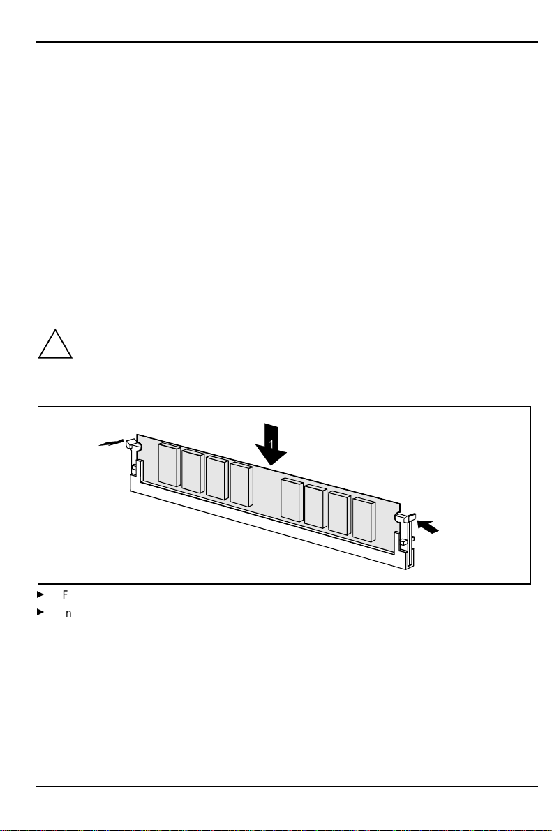
Installing memory modules
2
2
Flip the holders on each side of the relevant location outwards.
Insert the memory module in the slot while folding the side holders up until the memory module
engages (2).
Add-on modules
12 - English U41090-J-Z156-2-74
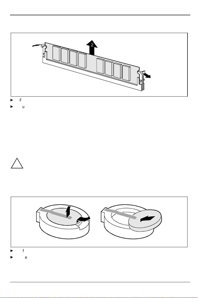
Removing a memory module
1
1
Flip the holders to the right and left of the location outwards (1).
Pull the memory module out of its location (2).
SCSI LVD connection
The SCSI LVD connection leads via a cable to an external standard SCSI connection. This makes it
possible to connect external SCSI devices to SCSI channel A of the onboard SCSI controller (see
the operating manual).
Replacing the lithium battery
!Incorrect replacement of the lithium battery may lead to a risk of explosion.
The lithium battery must be replaced with an identical battery or a battery type
recommended by the manufacturer (CR2032).
Do not throw lithium batteries into the trashcan. It must be disposed of in accordance with
local regulations concerning special waste.
Make sure that you insert the battery the right way round. The plus pole must be on the
top!
123
+
+++
Lift the contact (1) a few millimeters and remove the battery from its socket (2).
Insert a new lithium battery of the same type in the socket (3).
Table of contents
Other Siemens Nixdorf Motherboard manuals

Siemens Nixdorf
Siemens Nixdorf D818 User manual

Siemens Nixdorf
Siemens Nixdorf D969 User manual

Siemens Nixdorf
Siemens Nixdorf D1156 User manual

Siemens Nixdorf
Siemens Nixdorf D858 User manual

Siemens Nixdorf
Siemens Nixdorf D970 User manual

Siemens Nixdorf
Siemens Nixdorf D824 User manual

Siemens Nixdorf
Siemens Nixdorf D931 User manual

Siemens Nixdorf
Siemens Nixdorf D756 User manual

Siemens Nixdorf
Siemens Nixdorf D1025 User manual

Siemens Nixdorf
Siemens Nixdorf D1042 User manual


