Siemens Nixdorf D931 User manual

System board D931
Technical Manual

Dieses Handbuch wurde auf Recycling-Papier gedruckt.
This manual has been printed on recycled paper.
Ce manuel est imprimé sur du papier recyclé.
Este manual ha sido impreso sobre papel reciclado.
Questo manuale è stato stampato su carta da riciclaggio.
Denna handbok är tryckt på recyclingpapper.
Dit handboek werd op recycling-papier gedrukt.
Herausgegeben von/Published by
Siemens Nixdorf Informationssysteme AG
D-33094 Paderborn
D-81730 München
Bestell-Nr./Order No.: A26361-D931-Z121-5-7619
A26361-D931-Z121-5-7619A26361-D931-Z121-5-7619
A26361-D931-Z121-5-7619
Printed in the Federal Republic of Germany
AG 1296 12/96
A26361-D931-Z121-1-7619

Is there ...
...any technical problem or other
question you need clarified?...
Please contact:
• one of our IT Service Shops
• your sales partner
• your sales office
You will find the addresses of the
IT Service Shops in the enclosed
warranty coupon booklet.
... anything you want to tell us
about this manual?
Please send us your comments quoting
the order number of the manual.
Siemens Nixdorf Informationssysteme AG
Redaktion BS2000 OS ID4
Otto-Hahn-Ring 6
D-81730 München
Germany


System board D931
Technical Manual
Introduction
Important notes
Settings in BIOS-Setup
Jumper settings
Add-on modules
Error messages
Index
December 1996 edition

Your training needs . . .
The Siemens Nixdorf Training Centers offer you a wide range of training courses
in information technology and on IT products and other subjects - onsite near to
your workplace or offsite at one of our training centers.
Contact us for information on consulting, course schedules and selfstudy material
Please fax:
Fax: ++49 89 636-42945
Or write to:
Siemens Nixdorf Informationssysteme AG
Training Center, Beratungsservice
D-81730 München
Germany
Adaptec is a registered trademark of Adaptec Inc.
Intel, the Logo „intel inside“ and Pentium are registered trademarks and OverDrive is a trademark of
Intel Corporation, USA.
Microsoft, MS, MS-DOS, Windows and Windows 95 are registered trademarks of Microsoft
Corporation.
PS/2 and OS/2 Warp are registered trademarks of International Business Machines, Inc.
All other trademarks referenced are the trademarks or registered trademarks of their respective owners,
whose protected rights are acknowledged.
Copyright ãSiemens Nixdorf Informationssysteme AG 1995.
All rights, including rights of translation, reproduction by printing, copying or similar methods, even
of parts are reserved.
Offenders will be liable for damages.
All rights, including rights created by patent grant or registration of a utility model or design, are
reserved.
Delivery subject to availability; right of technical modifications reserved.

A26361-D931-Z121-5-7619
Contents
Introduction........................................................................................................... 1
Notational conventions............................................................................................ 1
Features................................................................................................................... 2
Ports and connectors ............................................................................................... 3
Interrupt table.......................................................................................................... 4
Important Notes .................................................................................................... 5
Modules with ESDs ......................................................................................... 5
CE certificate ................................................................................................... 6
Program with time loops......................................................................................... 6
Settings in BIOS Setup ......................................................................................... 7
Main menu - System settings................................................................................... 7
System Time / System Date ............................................................................. 8
Diskette A / Diskette B .................................................................................... 8
HardDisk1toHardDisk4............................................................................. 9
Boot Options.................................................................................................. 12
Video Display ................................................................................................ 13
Base Memory................................................................................................. 13
Extended Memory.......................................................................................... 13
Menu Advanced - Making advanced system settings............................................ 14
Cache Memory............................................................................................... 15
Shadow Memory............................................................................................ 17
Peripheral Configuration................................................................................ 18
PCI Configuration.......................................................................................... 21
Advanced System Configuration.................................................................... 22
Plug & Play O/S............................................................................................. 23
Reset Configuration Data............................................................................... 23
Large Disk Access Mode............................................................................... 24
Menu Security - Setting up the security features................................................... 25
Setup Password / System Password ............................................................... 25
Set Setup Password........................................................................................ 26
SetupPasswordLock..................................................................................... 26
Set System Password...................................................................................... 26
System Password Mode ................................................................................. 26
System Load................................................................................................... 27
Setup Prompt.................................................................................................. 27
Virus Warning................................................................................................ 27

Contents
A26361-D931-Z121-5-7619
Diskette Write - Write protection for floppy disk drive .................................28
Flash Write - Write protection for System BIOS ...........................................28
Soft Power Off ...............................................................................................28
Remote Power On ..........................................................................................28
Power menu - Setting energy saving functions......................................................29
APM...............................................................................................................29
Power Management Mode..............................................................................30
Standby Timeout ............................................................................................30
Hard Disk Timeout.........................................................................................30
Standby CPU Speed .......................................................................................31
Wakeup Event ................................................................................................32
Exit menu - Exiting BIOS Setup............................................................................33
Save Changes & Exit......................................................................................33
Discard Changes & Exit.................................................................................33
Get Default Values.........................................................................................33
Load Previous Values.....................................................................................33
Save Changes .................................................................................................33
Jumper settings....................................................................................................35
Write protection for System BIOS - jumper FLP..................................................35
Recovering System BIOS - jumper RCV ..............................................................36
Write protection for floppy disk drive - jumper FDP............................................36
Clock speed - jumper F0-F2 and CF0-CF3 ...........................................................37
Add-on modules...................................................................................................39
Upgrading main memory.......................................................................................39
Installing memory modules ............................................................................40
Removing a memory module..........................................................................40
Replacing the processor.........................................................................................41
Replacing the lithium battery.................................................................................43
Error messages.....................................................................................................45
Messages d'erreur................................................................................................47
Mensajes de error................................................................................................49
Messagi di errore.................................................................................................51
Felmeddelanden...................................................................................................53


A26361-D931-Z121-5-7619 1
Introduction
This description applies for the system board D931 with PCI bus (Peripheral
Component Interconnect).
Notational conventions
The meanings of the symbols and fonts used in this manual are as follows:
!
This indicates instructions which it is essential to observe. Failure to do
so may endanger your health, the operational integrity and electrical
safety of your PC, or the security of your data.
i
This symbol is followed by supplementary information, remarks and tips.
Ê Texts which follow this symbol describe activities that must be performed in
the order shown.
ËThis symbol means that you must enter a blank space at this point.
↵This symbol means that you must press the Enter key.
Texts in this typeface are screen outputs from the PC.
Texts in this bold typeface are the entries you make via the keyboard.
Texts in italics indicate commands or menu items.
"Quotation marks" indicate highlighted text and names of chapters."

Introduction Features
2A26361-D931-Z121-5-7619
Features
• 64-bit microprocessor Pentium with 16 Kbytes internal cache (first-Level
Cache, 8 Kbytes data cache, 8 Kbytes address cache) or
OverDrive processor for Pentium Pro
• Memory configuration on system board: 8 Mbytes to 256 Mbytes
• 256 Kbytes Flash BIOS
• PCI bus
• IDE hard disk controller connected to PCI bus for up to four IDE drives
(e.g. IDE hard disk drives, ATAPI CD ROM drive)
• Real-time clock/calendar with integrated battery backup
• Floppy disk controller (up to 2.88 Mbytes format)
• Bus interface for platter
• Connector for remote-on (fax/modem board), serial port (SER2, TTL),
chipcard reader and infrared interface
• Parallel port (ECP- and EPP-compatible)
• 2 serial ports
• PS/2 mouse port
• PS/2 keyboard port
• Piezo loudspeaker
• Security functions

Ports and connectors Introduction
A26361-D931-Z121-5-7619 3
Ports and connectors
1234568
910
11 12
15
16
17
18
20
21
22
7
13 14
19
1 = Parallel interface
2 = Serial port 2
3 = Serial port 1
4= PS/2mouseport
5= PS/2keyboardport
6 = Connector for power supply
7 = Connector for chipcard reader connection
8 = Connector for power supply 3,3 V
9 = Soft off power supply
10 = Connector for floppy disk drive
11 = Connector 1 for IDE drives 1 and 2
(e.g.harddiskdrive)
12 = Connector 2 for IDE drives 3 and 4
13 = Connector for device loudspeaker
14 = Connector for infrared interface
15 = Connector for LED indicators
16 = Connector for LED indicators
17 = Connector for infrared interface and LED
indicators
18 = Connector for fan
19 = Connector for On/Off switch
20 = Bus interface
21 = Connector for remote-on
22 = Connector for Serial port 2 SER2 (TTL)
The connectors marked do not have to be present on the system board.
i
If the connector for the chipcard reader port is used, no device may be
connected to serial interface 1.
If the connector for the serial interface SER2 (TTL) is used, no device
may be connected to the serial interface 2.

Introduction Interrupt table
4A26361-D931-Z121-5-7619
Interrupt table
Address Assigned IRQ Possible IRQ
Keyboard IRQ1
Cascade IRQ2
COM2 dispatcher 02F8 IRQ3
Serial interface COM1 03F8 IRQ4
IRQ5
Floppy disk drive controller IRQ6
Parallel interface LPT1 IRQ7
RTC IRQ8
IRQ9
IRQ10
IRQ11
Mouse controller IRQ12
Numeric processor IRQ13
IDE controller 1 IRQ14
IDE controller 2 IRQ15
„Assigned IRQ“ = interrupts assigned as shipped
„Possible IRQ“ = these interrupts can be used for your particular application
i
Please note that an interrupt cannot be used by two applications at the
same time.
A26361-D931-Z121-5-7619 5
Important Notes
!
Be sure to read this page carefully and note the information before you
open the PC.
Please note the information provided in the chapter "Safety" in the
Operating Manual of the PC.
Incorrect replacement of the lithium battery may lead to a risk of
explosion. It is therefore essential to observe the instructions in the
section "Replacing the lithium battery“.
The lithium battery must be replaced with an identical battery or a battery
type recommended by the manufacturer (CR2032).
Do not throw lithium batteries into the trashcan. Your vendor or dealer or
their authorized representatives will take used batteries back free of
charge so that they can be recycled or disposed of in the proper manner.
Connecting cable for peripherals must be adequately insulated to avoid
interference.
ADVARSEL
!
Lithiumbatteri - Eksplosionsfare ved fejlagtig håndtering. Udskiftning må
kun ske med batteri af samme fabrikat og type. Lever det brugte batteri
tilbage til leverandøren.
ADVARSEL
!
Eksplosjonsfare ved feilaktig skifte av batteri. Benytt samme batteritype
eller en tilsvarende type anbefalt av apparatfabrikanten. Brukte batterier
kasseres i henhold til fabrikantens instruksjoner.
VARNING
!
Eksplosionsfara vid felaktigt batteribyte. Använd samma batterityp eller
en ekvivalent typ som rekommenderas av apparattillverkarenfabrikanten.
Kassera använt batteri enligt fabrikantens instruktion.
VAROITUS
!
Paristo voi räjähtää, jos se on virheellisesti asennettu. Vaihda paristo
ainoastaan laitevalmistajan suosittelemaan tyyppiin. Hävitä käytetty
paristo valmistajan ohjeiden mukaisesti.
Modules with ESDs
Modules with electrostatic sensitive devices (ESD) may be identified by labels.
Important Notes Program with time loops
6A26361-D931-Z121-5-7619
When you handle modules fitted with ESDs, you must observe the following
points under all circumstances:
• When you handle modules fitted with ESDs, you must always discharge
yourself (e.g. by touching a grounded object) before working.
• Theequipmentandtoolsyouusemustbefreeofstaticcharges.
• Pull out the power plug before inserting or pulling out modules containing
ESDs.
• Always hold modules with ESDs by their edges.
• Never touch pins or conductors on modules fitted with ESDs.
CE certificate
This board complies with the requirements of the EEC directive
89/336/EEC with regard to "Electromagnetic compatibility".
Conformity was tested in the typical configuration of a Personal
Computer.
When installing the board, observe the specific installation notes in
the Operating Manual or Technical Manual for the appropriate
device.
Program with time loops
Problems can occur with programs in which time loops have been implemented
through software loops. This applies in particular to older programs which were
written for 8 MHz processors.

A26361-D931-Z121-5-7619 7
Settings in BIOS Setup
The BIOS Setup menu allows you to set your hardware configuration and system
functions. In addition, the BIOS Setup displays technical information on the PC's
configuration.
When it is supplied, the PC is set to factory default settings which you can alter in
the BIOS Setup menus. Any changes you make take effect as soon as you save the
settings and quit the BIOS Setup.
The Operating Manual describes how to call the BIOS Setup and change menu
entries.
You can select the following settings in the BIOS Setup:
Main - system functions
Advanced - advanced system configuration
Security - security features
Power - energy saving functions
Exit -saveandquit
i
The various menus are described below with all setting options. Since the
setting options depend on your PC's hardware configuration, some of
them may not be offered in the BIOS setup.
Main menu - System settings
In the Main menu you can set up the following:
• Time (in the field marked System Time)
• Date (in the field marked System Date)
• Floppy disk drive (in the field marked Diskette A or Diskette B)
• Hard disk drive (in the submenus of Hard Disk)
• System boot (in the submenus of Boot Options)
• Display device (in the field marked Video Display)

Settings in BIOS Setup Main menu - System settings
8A26361-D931-Z121-5-7619
Phoenix BIOS Setup Copyright 1985-94 Phoenix Technologies Ltd.
M
ain Advanced Security Power Exit
System Time: [07:42:19]
System Date: [08/11/1995]
Diskette A: [1.4M]
Diskette B: [None]
ÊHard Disk 1: 850 Mbyte
ÊHard Disk 2: None
ÊHard Disk 3: None
ÊHard Disk 4: None
ÊBoot Options
Video Display: [EGA/VGA]
Base Memory: 640K
Extended Memory: 7M
Item Specific Help
——————————————————————
F1 Help ↑↓ Select Item -/+ Change Values F9 Setup Defaults
ESC Exit ← → Select Menu Enter Execute Command F7 Previous Values
Example for Main menu
System Time / System Date
The System Time field and the System Date field show the time and date respectively
according to the PC. The time is shown in the format hh:mm:ss
(hours:minutes:seconds) and the date is shown in the format mm/dd/yyyy
(month/day/year).
!
If the settings in the System Time and System Date fields are frequently
wrong when you power up the computer, the lithium battery is dead.
Change the battery as described in "Replacing the lithium battery“.
Diskette A / Diskette B
These two fields are used to specify the type of floppy disk drive installed.
360K,720K,1.2M, 1.4M,2.8M
The entry depends on the floppy disk drive installed.
(Default entry Diskette A : 1.4M)
None A floppy disk drive is not installed.
(Default entry for Diskette B:)

Main menu - System settings Settings in BIOS Setup
A26361-D931-Z121-5-7619 9
HardDisk1toHardDisk4
call the submenu to make corresponding settings of the IDE hard disk drive.
i
You should change the default settings only if you are connecting an
additional IDE drive to one of the two IDE connectors.
The maximum transfer rate of two IDE drives connected to the same
connector is determined by the slower of the two. Fast hard disks
should therefore be connected to the first IDE connector and identified
as Hard Disk 1 or Hard Disk 2; slower hard disks or other IDE drives
(e.g. CD ROM drives) should be connected to the second IDE
connector and identified as Hard Disk 3 or Hard Disk 4.
The following description of the setting options for Hard Disk 1 also applies to Hard
Disk 2,Hard Disk 3 and Hard Disk 4. The default settings depend on the installed
drive.
Phoenix BIOS Setup Copyright 1985-94 Phoenix Technologies Ltd.
M
ain
Hard Disk 1: 850 Mbyte Item Specific Help
Autotype Hard Disk: [Press Enter]
Type: [User]
Cylinders: [ 1654]
Heads: [ 16]
Sectors/Track: [ 63]
Write Precomp: [None]
Transfer Mode: [Standard]
LBA Translation: [Disabled]
PIO Mode: [Standard]
32 Bit I/O: [Enabled]
F1 Help ↑↓ Select Item -/+ Change Values F9 Setup Defaults
ESC Exit ← → Select Menu Enter Execute Command F7 Previous Values
Example for the submenu Hard Disk 1
!
Only if you have installed a new unrecorded IDE hard disk drive, you
should mark the Autotype Hard Disk field.
If you have set the hard disk parameters with Autotype Hard Disk, you can
only reduce the values.
Settings in BIOS Setup Main menu - System settings
10 A26361-D931-Z121-5-7619
If you have installed a new unrecorded IDE hard disk drive, you should mark the
Autotype Hard Disk field and press Enter. This has the effect of setting the optimum
values for the IDE hard disk drive. You can change these values if you set the Type
field to User.
Type - Hard Disk Type
This field is used to specify the type of hard disk drive installed.
None You cannot change the hard disk parameters (Cylinders, Heads,
Sector/Track and Write Precomp). An IDE drive has not been
installed.
1to 39 The hard disk parameters (Cylinders, Heads, etc.) are preset.
Auto If the hard disk supports this mode, the setup menu reads the hard
disk parameters from the disk itself and sets them automatically.
You do not need to select the parameters yourself.
User You can enter the hard disk parameters (Cylinders, Heads etc.)
yourself.
If you have set the hard disk parameters with Autotype Hard Disk,
you can only reduce the values.
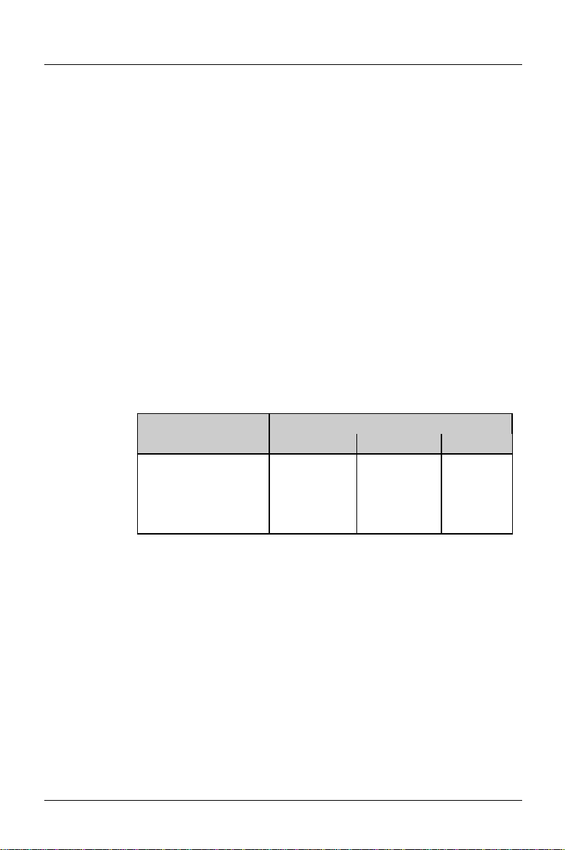
Examples of user-defined entries (IDE drives):
hard disk hard disk capacity
parameter 850 Mbyte 1Gbyte 1,6 Gbyte
Cylinders 1654 2097 3148
Heads 16 16 16
Sectors 63 63 63
Write Precomp None None None
CD If an ATAPI CD-ROM drive is mounted, this entry enables you to
boot from the CD-ROM drive.
Cylinders, Heads, Sectors/Track, Write Precomp - hard disk parameter
These hard disk parameters are set in accordance with the IDE hard disk drive. If
you want to change the hard disk parameters manually, set the Type field to User.
Table of contents
Other Siemens Nixdorf Motherboard manuals

Siemens Nixdorf
Siemens Nixdorf D756 User manual

Siemens Nixdorf
Siemens Nixdorf D1156 User manual

Siemens Nixdorf
Siemens Nixdorf Fujitsu D1115 User manual

Siemens Nixdorf
Siemens Nixdorf D818 User manual

Siemens Nixdorf
Siemens Nixdorf D1085 User manual

Siemens Nixdorf
Siemens Nixdorf D824 User manual

Siemens Nixdorf
Siemens Nixdorf D970 User manual

Siemens Nixdorf
Siemens Nixdorf D1111 User manual

Siemens Nixdorf
Siemens Nixdorf D969 User manual

Siemens Nixdorf
Siemens Nixdorf D1025 User manual


