Siemens Nixdorf D1025 User manual
A26361-D1025-Z120-7-7419 English - 1
Introduction
This description applies for the system board D1025 with PCI bus (Peripheral Component
Interconnect).
iThis system board is available in different configuration levels. Depending on the
hardware configuration of your device, it may be that you cannot find several options in
your version of the system board, even though they are described.
You may find further information in the description "BIOS Setup".
Further information to drivers is provided in the readme files on hard disk or on the supplied drivers
diskettes or on the "Drivers & Utility" or "ServerStart" CD.
Notational conventions
The meanings of the symbols and fonts used in this manual are as follows:
!Pay particular attention to texts marked with this symbol. Failure to observe this warning
endangers your life, destroys the system, or may lead to loss of data.
iThis symbol is followed by supplementary information, remarks and tips.
Texts which follow this symbol describe activities that must be performed in the order shown.
This symbol means that you must enter a blank space at this point.
This symbol means that you must press the Enter key.
Texts in this typeface are screen outputs from the PC.
Texts in this bold typeface are the entries you make via the keyboard.
Texts in italics indicate commands or menu item.
"Quotation marks" indicate names of chapters and terms that are being emphasized.
Introduction
2 - English A26361-D1025-Z120-7-7419
Important notes
Store this manual close to the device. If you pass on the device to third parties, you should also
pass on this manual.
!Be sure to read this page carefully and note the information before you open the PC.
You cannot access the components of the system board without first opening the device.
How to dismantle and reassemble the device is described in the Operating Manual
accompanying the device.
Please note the information provided in the chapter "Safety" in the Operating Manual of
the PC.
Incorrect replacement of the lithium battery may lead to a risk of explosion. It is therefore
essential to observe the instructions in the chapter „Add-on modules“ - „Replacing the
lithium battery“.
The lithium battery must be replaced with an identical battery or a battery type
recommended by the manufacturer (CR2032).
Do not throw lithium batteries into the trashcan. It must be disposed of in accordance with
local regulations concerning special waste.
The shipped version of this board complies with the requirements of the EEC
directive 89/336/EEC "Electromagnetic compatibility".
Compliance was tested in a typical PC configuration.
When installing the board, refer to the specific installation information in the
Operating Manual or Technical Manual of the receiving device.
Connecting cables for peripherals must be adequately insulated to avoid interference.
!Components can become very hot during operation. Make sure you do not touch
components when making extensions to the system board. There is a danger of burns!
iThe warranty expires if the device is damaged during the installation or replacement of
system expansions. Information on which system expansions you can use is available
from your sales office or the customer service.

Introduction
A26361-D1025-Z120-7-7419 English - 3
Boards with electrostatic sensitive devices (ESD) may be identified by labels.
When you handle boards fitted with ESDs, you must observe the following points under all
circumstances:
• You must always discharge yourself (e.g. by touching a grounded object) before working.
• The equipment and tools you use must be free of static charges.
• Pull out the power plug before inserting or pulling out boards containing ESDs.
• Always hold boards with ESDs by their edges.
• Never touch pins or conductors on boards fitted with ESDs.

Features
4 - English A26361-D1025-Z120-7-7419
Features
• LPX system board
• 64-bit microprocessor Intel Pentium with MMX, with 32 Kbytes internal cache (first-Level
Cache, 16 Kbytes data cache, 16 Kbytes address cache) or OverDrive-Processor for Pentium
or
• Prepared for AMD-K6 or Cyrix M2
• The system board supports Pentium MMX™.
• 512 Kbyte Second Level Cache
• Memory configuration on the system board: 8 to 256 Mbyte (SDRAM)
• 2 Mbit Flash BIOS
• PCI bus
• IDE hard disk controller connected to PCI bus for up to four IDE drives
(e.g. IDE hard disk drives, ATAPI CD-ROM drives), (prepared for ultra DMA33 mode), supports
PIO modes 0-4
• Supports booting from a 120 Mbyte floppy disk drive
• Floppy disk controller (up to 2.88 Mbytes format)
• Real-time clock/calendar with integrated battery backup
• Parallel interface (ECP- and EPP-compatible)
• 1 serial port (16C550 compatible with FIFO)
• PS/2 mouse port
• PS/2 keyboard port
• Security functions
• Prepared for Siemens system monitoring
• Prepared for Rainbow Runner video module

Features
A26361-D1025-Z120-7-7419 English - 5
• Video connector
• 64 bit screen controller connected to PCI bus, graphics processor Matrox MGA 1064SG
(Mystique Cyclone) with Windows accelerator, 3D accelerator and 2 Mbyte SGRAM video
memory
• Video memory can be upgraded to 4 or 8 Mbytes of SGRAM (original Matrox memory upgrade)
• Audio controller on ISA-BUS (PnP) Crystal CS 4235 Audio Codec or CS 4236 Audio Codec,
16 bit stereo; compatible with Soundblaster Pro™, Windows Sound System and MPU 401;
3D audio support (only for CS4235); internal FM synthesis
iThe audio output can be set in the BIOS Setup in the screen Advanced/Peripheral
Configuration, menu option Audio Output to Line Level or Full Power. Use Line Level
if you connect headphones or an active loudspeaker (with amplifier) to the audio
output. Use Full Power if you use passive loudspeakers.
• USB (Universal Serial Bus)
• Energy saving functions
• Connector for feature connector, loudspeaker
• Connector for remote-on (fax/modem board), chipcard reader and infrared interface
• Connector for CD-line in, Game/Midi, Voice-Modem, AUX IN
• Microphone jack
• Audio input (Line in)
• Connector for headphones or active speakers
Optional Components
• LAN port
• I2C connector
Features
6 - English A26361-D1025-Z120-7-7419
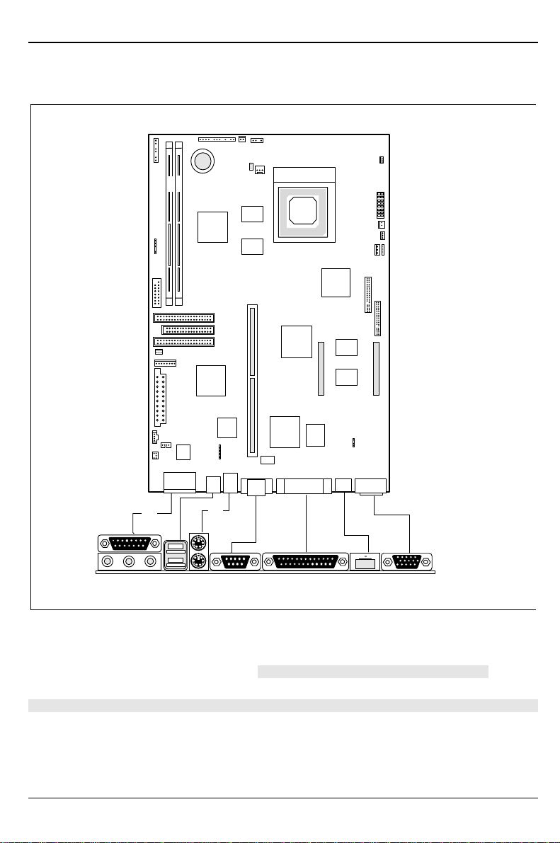
Interfaces and connectors
1 2
45 67 8 9 10
12
311
1 = MIDI/Game port
2 = PS/2 mouse port
3 = Audio port (Headphones, Line out)
4 = Audio port (Line in)
5 = Audio port (Microphone)
6 = USB ports
7 = PS/2 keyboard port
8 = Serial port 1
9 = Parallel interface
10 = LAN port
11 = Video connector
The connectors marked do not have to be present on the system board.

Features
A26361-D1025-Z120-7-7419 English - 7
1
2
8
9
10
13
14
15
16
18
19
20
11
12
17
7
5423
6
1
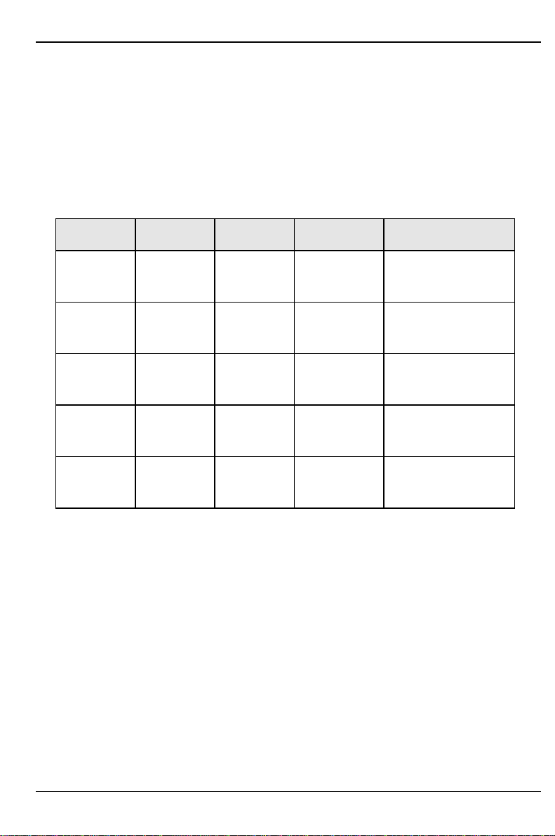
1 = Connector 2 for control panel
2 = Connector 1 for control panel
3 = ON/OFF button
4 = Loudspeaker
5 = Fan
6 = Connector for fax boards
7 = Wake On LAN
8 = SCSI indicator
9 = I2C connector
10 = Feature connector
11 = LAN_OFF jumper
12 = Voice modem
13 = AUX IN
14 = CD Line in
15 = Power supply 1
16 = Power supply 2
17 = IDE drives 3 and 4 (secondary)
18 = Floppy disk drive
19 = IDE drives 1 and 2 (primary)
20 = Connector for chipcard reader
21 = IrDA
The connectors marked do not have to be present on the system board.

Features
8 - English A26361-D1025-Z120-7-7419
LAN port
The LAN RJ45 connector is equipped with a yellow and a green LED (light emitting diode).
Normal mode
Yellow indicator Signals that a connection exists (e.g. hub).
Green indicator Signals that activity is present on the LAN port.
WOL mode
Yellow indicator Signals that a connection exists (e.g. hub).
Green indicator Signals that a Magic PacketTM is being received.
i• To use the LAN controller the power supply must provide a 5V auxiliary
voltage of at least 500 mA.
• If you want to use the WOL functionality (WOL = Wake On LAN) you have to
make the relevant settings in BIOS Setup.
Otherwise malfunctions may occur. Please contact our customer service.
The onboard LAN controller may be switched off by the LAN_OFF jumper.
If you want to switch off the onboard LAN controller insert a jumper to position 1-2 of the
LAN_OFF jumper.
Features
A26361-D1025-Z120-7-7419 English - 9
Possible screen resolution
Depending on the operating system used the screen resolutions in the following table refer to the
screen controller on the system board. If you are using an external screen controller, you will find
details of supported screen resolutions in the Operating Manual or Technical Manual supplied with
the controller.
To select the appropriate setting for your monitor, please use the Matrox VGA drivers supplied.
In Windows 95 you can select your monitor type (you should possibly use the standard type) and
the resolution in the "Control Panel" under „Display Properties“ in the tabs „MGA-Monitor“ and „MGA
settings“ after these drivers have been installed.
Screen
resolution Refresh rate
(Hz) Horizontal-
rate (kHz) Max. number of
colors (2MB) Max. number of colors
(4MB / 8MB)
640x480 120 31 to 51 256 256
640x480 120 31 to 51 64 K 64 K
640x480 120 31 to 51 16 mio. 16 mio.
800x600 120 37 to 77 256 256
800x600 120 37 to 77 64 K 64 K
800x600 120 37 to 77 16 mio. 16 mio.
1024x768 120 48 to 98 256 256
1024x768 120 48 to 98 64 K 64 K
1024x768 120 48 to 98 - - 16 mio.
1152x864 110 57 to 100 256 256
1152x864 110 57 to 100 64 K 64 K
1152x864 110 57 to 100 - - 16 mio.
1280x1024 100 62 to 107 256 256
1280x1024 100 62 to 107 - - 64 K
1280x1024 100 62 to 107 - - 16 mio.
- - Not available; * : this value is only available with 8 MB.
64 K: high color (16 bit); 16 million: true color (24 bit)

Features
10 - English A26361-D1025-Z120-7-7419
Screen
resolution Refresh rate
(Hz) Horizontal-
rate (kHz) Max. number of
colors (2MB) Max. number of colors
(4MB / 8MB)
1600x1024 85 71 to 96 256 256
1600x1024 85 71 to 96 - - 64K
1600x1024 85 71 to 96 - - 16 mio.*
1600x1200 84 71 to 105 256 256
1600x1200 84 71 to 105 - - 64 K
1600x1200 75 71 to 105 - - 16 mio.*
1600x1280 75 94 to 100 256 256
1600x1280 75 94 to 100 - - 64 K
1600x1280 72 94 to 100 - - 16 mio.*
- - Not available; * : this value is only available with 8 MB.
64 K: high color (16 bit); 16 million: true color (24 bit)

Features
A26361-D1025-Z120-7-7419 English - 11
Resource table
assigned
IRQ possible IRQ Possible
Address Possible
DMA
Keyboard IRQ1
IrDA / chip card reader IRQ3 02F8, 03F8
02E8, 03E8
Serial interface COM1 IRQ4 03F8, 02F8
03E8, 02E8
Floppy disk drive controller IRQ6 DMA2
Parallel interface LPT1 IRQ7 IRQ5, IRQ7 0278, 0378 DMA1, DMA3
RTC IRQ8
Audio controller
Joystick:
Base address:
MPU 401:
Adlib:
IRQ5, IRQ7,
IRQ9, IRQ11,
IRQ12, IRQ15 0200-0207
0220-022F
0240-024F
0260-026F
0280-028F
0300-0301
0330-0331
0338-038B
DMA1, DMA3,
DMA0
USB controller IRQ11
Mouse controller IRQ12
Numeric processor IRQ13
IDE controller 1 IRQ14
IDE controller 2 IRQ15
"assigned IRQ" = interrupts assigned as shipped
"Possible IRQ" = these interrupts can be used for your particular application
"Possible address" = this address can be used for your particular application
"Possible DMA" = these DMAs can be used for your particular application
iMPU 401: If you want to use external MIDI devices (for example a MIDI keyboard), you
must assign an interrupt for the MPU 401 (MIDI interface). Detailed information is
provided in the audio documentation on the driver and utility CD.
Please note that a resource cannot be used by two applications at the same time.
Settings with switches
12 - English A26361-D1025-Z120-7-7419
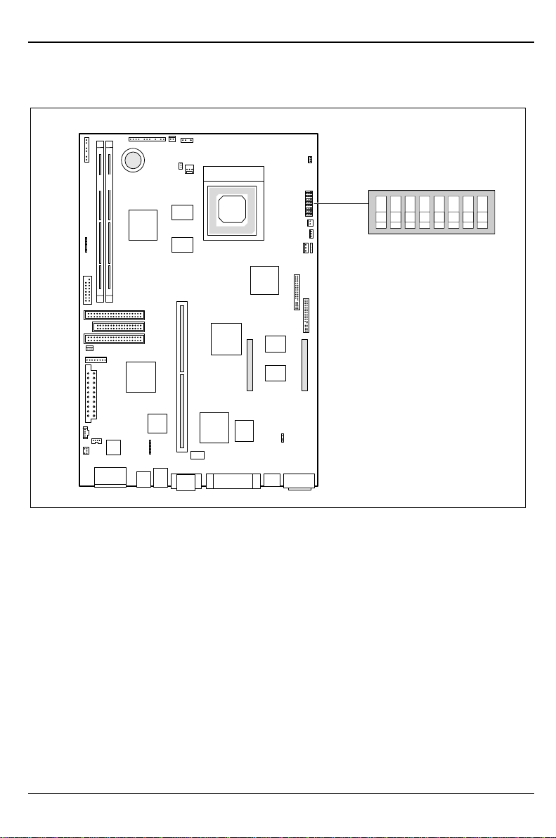
Settings with switches
1
2
OPEN/OFF
12345678
ON
Switch 1, 2, 3 and 4 = clock speed
Switch 5 = recovering system BIOS
Switch 6 = must be set to off
Switch 7 = reserved
Switch 8 = write protection for floppy disk drive
Settings with switches
A26361-D1025-Z120-7-7419 English - 13
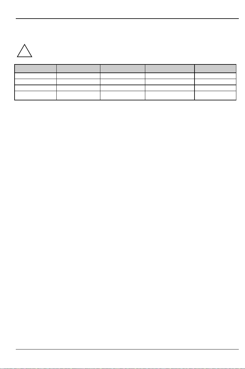
Clock speed - switch 1, 2, 3 and 4
!The switches may only be set as specified in the table below for the particular processor
used.
Processor switch 1 switch 2 switch 3 switch 4
166 MHz on off on on
200 MHz on off off on
233 MHz on off off off
Reserved off off off off
Recovering System BIOS - switch 5
Switch 5 enables recovery of the old system BIOS after an attempt to update has failed. Memory
bank 1 must be populated in order to be able to restore the system BIOS. To restore the old BIOS
you need a Flash BIOS Diskette (call customer service).
on The System BIOS executes from floppy drive A: and restores the System BIOS on
the system board.
off The System BIOS is started from the system board (default setting).
Write protection for floppy disk drive - switch 8
Switch 8 is used to define whether floppy disks can be written or deleted in the floppy disk drive. To
write and delete floppy disks, the write protection in BIOS setup must be disabled (in menu Security,
the field Diskette Write must be set to Enabled).
on The floppy disk drive is write-protected.
off Read, write and delete floppy disks is possible (default setting).

Add-on modules
14 - English A26361-D1025-Z120-7-7419
Add-on modules
!For all steps described in this chapter pull the power plug out of the power outlet!
1
2
5
423
6
7
1
8
9
1 = Locations bank 1 for main memory
2 = Locations bank 2 for main memory
3 = Lithium battery
4 = Processor with heat sink and fan
5 = VCore jumper for processor core voltage
6 = Socket for video memory board
7 = Slot for platter
8 = Flash BIOS
9 = Socket for wavetable chip
iAll PCI slots have bus master capability.

Add-on modules
A26361-D1025-Z120-7-7419 English - 15
Upgrading main memory
Two locations (bank 1 and bank 2) are available on the system board for installing memory
modules. DIMM modules (dual inline memory module) are used.
A maximum of 256 Mbytes of SDRAM memory modules may be installed. SDRAM memory
modules can be mixed.
!You may only use unbuffered 3.3V modules. Buffered modules are not permitted.
You can only use 66 MHz or faster SDRAM memory modules!
Installing memory modules
Flip the retainers to the left and right of the location outward.
Insert the memory module into the appropriate location.
Press the lateral holders until they snap in place.
Press the lateral holders firmly against the location.
Removing a memory module
Flip the holders to the right and left of the location outwards.
Pull the memory module out of its location.
Add-on modules
16 - English A26361-D1025-Z120-7-7419
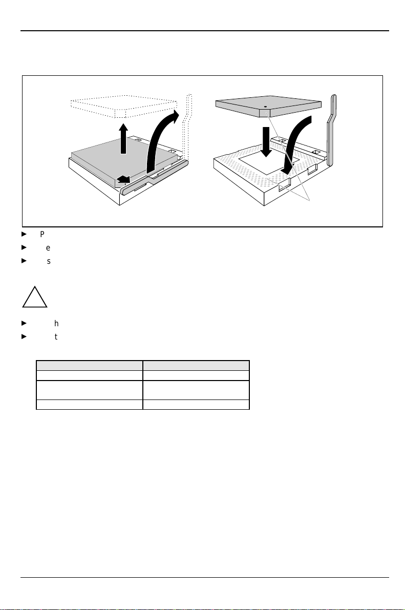
Replacing the processor
32
1
A
45
Push the lever in the direction of the arrow (1) and lift it as far as it will go (2).
Remove the old processor from the socket (3).
Insert the new processor in the socket so that the mark on the upper side of the processor
matches the mark (A) on the socket (4).
!The mark on the processor may be covered by a heat sink. In this case let yourself be
guided by the marking in the rows of pins on the underside of the processor.
Push the lever back down so that it snaps into place.
Set the switches 1, 2 , 3 and 4 depending on the processor which is installed.
Setting the processor core voltage
Processor type Jumper VCore
Intel not inserted
AMD-K6 - 166
AMD-K6 - 200 connected to 1-2
AMD-K6 - 233 connected to 2-3

Add-on modules
A26361-D1025-Z120-7-7419 English - 17
Upgrading the video memory
If 2 MB of video memory is installed on the system board, you can increase the video memory to 4
or 8 Mbytes.
1
!Check that the memory extension is correctly aligned before you press it into the
base on the system board. The pins on the connector strip must fit exactly into the
openings of the female connectors. Otherwise the memory extension might be
damaged.
Upgrading the wavetable module
If the system board is prepared for upgrading with a single-chip wavetable module (Crystal
CS9236), the upgrade is carried out as shown in the figure.

Add-on modules
18 - English A26361-D1025-Z120-7-7419
Replacing the lithium battery
!Incorrect replacement of the lithium battery may lead to a risk of explosion.
The lithium battery must be replaced with an identical battery or a battery type
recommended by the manufacturer (CR2032).
Do not throw lithium batteries into the trashcan. It must be disposed of in accordance with
local regulations concerning special waste.
Make sure that you insert the battery the right way round. The plus pole must be on the
top!
1
23
+
+++
Lift the contact (1) a few millimeters and remove the battery from its socket (2).
Insert a new lithium battery of the same type in the socket (3).

A26361-D1025-Z120-7-7419
Contents
Introduction....................................................................................................................................... 1
Notational conventions.............................................................................................................. 1
Important notes......................................................................................................................... 2
Features ........................................................................................................................................... 4
Interfaces and connectors......................................................................................................... 6
LAN port.................................................................................................................................... 8
Possible screen resolution........................................................................................................ 9
Resource table........................................................................................................................ 11
Settings with switches..................................................................................................................... 12
Clock speed - switch 1, 2, 3 and 4 .......................................................................................... 13
Recovering System BIOS - switch 5 ....................................................................................... 13
Write protection for floppy disk drive - switch 8 ....................................................................... 13
Add-on modules.............................................................................................................................. 14
Upgrading main memory......................................................................................................... 15
Replacing the processor ......................................................................................................... 16
Upgrading the video memory .................................................................................................. 17
Upgrading the wavetable module............................................................................................ 17
Replacing the lithium battery................................................................................................... 18

A26361-D1025-Z120-7-7419
A26361-D1025-Z120-7-7419
System board D1025
Technical Manual
October 1998 edition
Creative is a registered trademark, Sound Blaster 16 and VIBRA 16C are trademarks of Technology
Ltd.
Intel and Pentium are registered trademarks and MMX and OverDrive are trademarks of Intel
Corporation, USA.
AMD-K6 is a trademark of Advanced Micro Devices, Inc.
Microsoft, MS, MS-DOS and Windows are registered trademarks of Microsoft Corporation.
PS/2 and OS/2 Warp are registered trademarks of International Business Machines, Inc.
All other trademarks referenced are trademarks or registered trademarks of their respective owners,
whose protected rights are acknowledged.
Copyright Siemens Nixdorf Informationssysteme AG 1998.
All rights, including rights of translation, reproduction by printing, copying or similar methods, even of
parts are reserved.
Offenders will be liable for damages.
All rights, including rights created by patent grant or registration of a utility model or design, are
reserved.
Delivery subject to availability. Right of technical modification reserved.
Table of contents
Other Siemens Nixdorf Motherboard manuals

Siemens Nixdorf
Siemens Nixdorf D1156 User manual

Siemens Nixdorf
Siemens Nixdorf D824 User manual

Siemens Nixdorf
Siemens Nixdorf D1111 User manual

Siemens Nixdorf
Siemens Nixdorf D970 User manual

Siemens Nixdorf
Siemens Nixdorf Fujitsu D1160 User manual

Siemens Nixdorf
Siemens Nixdorf D818 User manual

Siemens Nixdorf
Siemens Nixdorf D858 User manual

Siemens Nixdorf
Siemens Nixdorf D802-C User manual

Siemens Nixdorf
Siemens Nixdorf Fujitsu D1115 User manual

Siemens Nixdorf
Siemens Nixdorf D808 User manual


