Siemens Nixdorf D802-C User manual

PC
System board II
PCD-H
The Intel Inside Logo is
a registered trademark
Technical Manual of Intel Corporation

PC
Published by
Siemens Nixdorf Informationssysteme AG
33094 Paderborn
81730 München
Order No.: A26361-D802-Z121-1-7619
Printed in the Federal Republic of Germany
AG 0394 03/94
A26361-D802-Z121-1-7619

Is there ...
... any technical problem or other ... anything you want to tell us
question you need clarified? about this manual?
Please send us your comments quoting
Please contact: the order number of the manual.
– one of our IT Service Shops
– your sales partner Siemens Nixdorf Informationssysteme AG
– your sales office User Documentation Department
BS2000 QM2, Otto-Hahn-Ring 6,
You will find the addresses of the 81730 München, Germany
IT Service Shops in the enclosed
warranty coupon booklet. Fax: (0 89) 6 36-4 04 43
This manual was produced using paper treated with chlorine-free bleach.
Introduction
Important notes
Setup menu
System board II
PCD-H Settings and
add-on modules
Interface assignment
Error messages
Technical Manual
Index
May 1994 edition

Would you like to know more ...
... about this product
... or about another aspect of information technology?
Our Training Centers will be glad to help.
Siemens Nixdorf has Training Centers at strategic
locations in Germany and more than 20 countries worldwide.
Please write to:
Siemens Nixdorf
Area Training Management Europe North
125-135 Staines Road, Hounslow, Middlesex, TW3 3JB
United Kingdom
or call
Ron Johnson, Hounslow
Tel.: .44 344 850 990
Fax.: .44 344 850 991
Adaptec is a registered trademark of Adaptec Inc
Intel is a registered trademark, i486 SX, i487 SX, i486 DX, i486 DX2, OverDrive and Pentium
are trademarks of Intel Corporation, USA.
Microsoft, MS and MS-DOS are registered trademarks and Windows is a trademark of
Microsoft Corporation.
Novell and NetWare are registered trademarks of Novell, Inc.
UNIX is a registered trademark of UNIX System Laboratories.
Copyright Siemens Nixdorf Informationssysteme AG 1994
The reproduction, transmission or use of this document or its contents is not permitted without
express written authority.
Offenders will be liable for damages
All rights, including rights created by patent grant or registration of a utility model or design,
are reserved.
Delivery subject to availability. Right of technical modification reserved.

Contents
Introduction 1
Explanation of symbols 1
Features 2
Important notes 5
Notes on software 6
Setup menu 7
Settings in the setup menu 8
Entries on the first page of the setup menu 8
Entries on the second screen page of the setup menu 11
Entries on the third screen page of the SETUP menu 16
Settings and add-on modules 21
Connector X90 for external CRT controller 21
Interrupt IRQ12 22
VGA controller 22
Floppy disk drive 22
Primary CRT controller 23
Processor 23
Upgrading 24
Main memory 25
Installing a memory module 26
Removing a memory module 26
Second level cache memory 27
Upgrading 27
Interface assignment 29
Connector X250 for power supply 29
Connector X251 for power supply 29
Connector for external loudspeaker X255 30
Connector X258 for indicator 30
Connector X90 for external monitor controller 31
Error messages 33
Index 35
A26361-D802-Z121-3-7619

Introduction
This description applies for the system board with ISA Bus.
Explanation of symbols
The meanings of the symbols and fonts used in this manual are as follows:
!Pay particular attention to texts marked with this symbol. Failure to observe
this warning endangers your life, destroys the system, or may lead to loss of
data.
This symbol is followed by supplementary information, remarks and tips.
i
Texts which follow this symbol describe activities that must be performed in the
order shown.
This symbol means that you must enter a blank space at this point.
↵ This symbol means that you must press the Enter key.
Texts in this typeface are screen outputs from the PC.
Texts in this bold typeface are the entries you make via the keyboard.
Texts in italics indicate commands or menu items.
"Quotation marks" indicate highlighted text and names of chapters.
A26361-D802-Z121-3-7619 1
Introduction
Features
– 32-bit microprocessor i486 SX/33 MHz (in PGA), i486 DX/33 MHz,
i486 DX2/50 MHz or i486 DX2/66 MHz with 8 Kbyte internal cache memory
(first level cache)
– Socket for Upgrade with OverDrive processor ODP486/33 MHz or
ODPR486/33 MHz
– Memory configuration on system board: 4 Mbyte to 32 Mbyte RAM onboard
– Second level cache memory on the system board: 0 oder 128 Kbyte
– Video memory on the system board: 1 Mbyte
– 114 Byte Setup memory in CMOS RAM
– BIOS can be copied into RAM
– Parts of the main memory can be copied into cache memory
– 128 Kbyte ROM
– Real-time clock/calendar with integrated battery backup
– Loudspeaker
– Floppy disk drive controller (up to 2.88 Mbyte format)
– Hard disk controller for IDE hard disk drives
– VGA controller connected to VESA Local Bus (graphics processor S3 86C805
with Windows accelerator)
– ISA bus interface
– Connector for IDE hard disk drive
– Connector for floppy disk drive
– Connector for external monitor controller
– Connector for external loudspeaker
– Parallel interface
– two serial interfaces
– Mouse interface
– Keyboard port
– Monitor interface
2A26361-D802-Z121-3-7619
Introduction
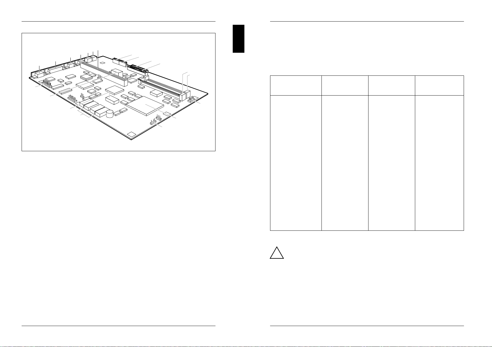
12346
578910 11 12
13
14
15
16
17
19
20
18
1 = Monitor interface 12 = Socket X150 for main memory
2 = Parallel interface Bank 0
3 = Serial interface (Ser 2) 13 = Socket X151 for main memory
4 = Serial interface (Ser 1) Bank 1
5 = Mouse interface (bus mouse) 14 = Connector X258 for indicator
6 = Keyboard port 15 = Socket D30 for processor
7 = ISA Bus interface 16 = Connector X255 for external
8 = Connector X250 for power supply loudspeaker
9 = Connector X251 for power supply 17 = Second level cache memory
10 = Connector X191 for floppy disk drive (D120, D130 to D133)
11 = Connector X100 for 18 = Lithium battery with connector
IDE hard disk drive 19 = Connector X90 for external
monitor controller
(VESA VGA Pass Through)
A26361-D802-Z121-3-7619 3
Introduction
Possible screen resolution
The screen resolutions in the following table refer to the VGA controller on the
system board.
If you are using an external CRT controller, you will find the possible screen
resolution in the Operating Manual of the CRT controller.
Screen Refresh Horizontal- Max. number
resolution rate (Hz) rate (kHz) of colours
640x350 70 31,4 16
640x350 84 37,8 16
640x480 60 31,5 16777160
640x480 73 37,9 65536
640x480 90 48 65536
720x400 70 31,4 16
720x400 84 37,8 16
800x600 56 35,4 65536
800x600 57 36,1 65536
800x600 60 37,8 65536
800x600 60 39 65536
800x600 72 48 256
800x600 75 49,5 256
800x600 90 60,3 256
1024x768 43,5 (interl.) 35,5 256
1024x768 60 49 256
1024x768 70 56,6 256
1024x768 75 60,1 256
1280x1024 43,5 (interl.) 49 16
1280x1024 60 63,6 16
The screen resolution depends on the connected monitor.
!You may set only those resolutions and refresh rates specified in the
"Technical data" section of the monitor description. Otherwise you may
damage your monitor. If you are in any doubt, contact your sales office or
customer service.
You can use the WDSETUP program (under MS-Windows) or the SET-VGA program
(under MS-DOS) to set the screen resolution. Detailed information is provided
under MS-Windows in the file VGA.WRI.
4A26361-D802-Z121-3-7619
Important notes
!Please note the information provided in the chapter "Safety" in the
Operating Manual of the PC.
The lithium battery on the board may only be replaced by specialist
technicians. There is a danger of explosion if this is not done properly.
The lithium battery must be replaced with an identical battery or a battery
type recommended by the manufacturer.
The lithium battery must be disposed of in accordance with local regulations
on the disposal of special refuse.
Be sure to read this page carefully and note the information before you
open the PC.
Modules with electrostatic sensitive devices (ESD) may be identified by labels.
When you handle modules fitted with ESDs, you must observe the following points
under all circumstances:
– When you handle modules fitted with ESDs, you must always discharge yourself
(e.g. by touching a grounded object) before working.
– The equipment and tools you use must be free of static charges.
– Pull out the power plug before inserting or pulling out modules containing ESDs.
– Always hold modules with ESDs by their edges.
– Never touch pins or conductors on modules fitted with ESDs.
A26361-D802-Z121-3-7619 5
Important notes
Notes on software
Program with time loops
Problems can occur with programs in which time loops have been implemented
through software loops. This applies in particular to older programs which were
written for 8 MHz processors.
SCO-UNIX on devices with processor i486 DX2 or OverDrive
If you upgrade the system board by adding a processor mentioned above, please
note the following:
If you use the processor mentioned above, the Adaptec-SCSI controller cannot be
addressed under SCO-UNIX 3.2.4 and ODT 2.0.
To solve this problem, you can order from SCO a set of SLS (Support Level
Supplement) floppies (consisting of 3 floppy disks) under the number uod361,
free of charge, or contact SNI's spare parts service.
The problem no longer exists in the new releases of SCO-UNIX 3.2.4.2 and
ODT 2.1.
There will be no support for older versions (SCO-UNIX versions lower than 3.2.4
and ODT versions lower than 2.0).
6A26361-D802-Z121-3-7619

Setup menu
CMOS Setup
System Configuration
---------------------------------------------------------------------------
Time (hh:mm:ss) 08:38:27 Date (mm/dd/yyyy) 07/26/1993
Diskette A: 1.4M
Diskette B: NONE
Cyl Hd Pre LZ Sec Mbyte
Hard Disk 1: 48 904 8 NONE 904 46 162
Hard Disk 2: NONE
Base Memory: 640K Video Display: EGA/VGA
Extended Memory: 3072K Math Coprocessor: YES
Speed Select: HIGH
ERROR HALT: HALT ON ALL ERRORS
---------------------------------------------------------------------------
<F1> Help <F8> System info <F10> Store CMOS <Esc> Exit Page
<...> Edit field <↑↓←→> Next field <PgUp> Next page <Ctrl> ... 01
Example of the first screen page of a setup menu
CMOS Setup
System Security Options
---------------------------------------------------------------------------
Time (hh:mm:ss) 08:38:27 Date (mm/dd/yyyy) 07/26/1993
System Load: STANDARD
Security Features: DISABLED
Serial 1: COM1 (3F8h) Diskette Write: ENABLED
Serial 2: COM2 (2F8h) Diskette Ctrlr: ENABLED
Parallel: LPT1 (378h) HD Ctrlr Mode: STANDARD
Par Mode: PRINTER HD Power Down: DISABLED
Hard Disk Ctrlr: ENABLED
Soft Power Off: DISABLED
---------------------------------------------------------------------------
<F1> Help <F8> System info <F10> Store CMOS <Esc> Exit Page
<...> Edit field <↑↓←→> Next field <PgUp> Next page <Ctrl> ... 02
Example of the second screen page of a setup menu
A26361-D802-Z121-3-7619 7
Setup menu
CMOS Setup
Additional System Options
---------------------------------------------------------------------------
Time (hh:mm:ss) 08:38:27 Date (mm/dd/yyyy) 07/26/1993
System BIOS: 64K
Shadow BIOS ROM: SYSTEM AND VIDEO BIOS
C800 CC00 D000 D400 D800 DC00
Shadow Adaptor ROM: NO NO NO NO NO NO
Cache:: INTERN AND EXTERN
Cache Shadow RAM:: VIDEO BIOS ONLY
C800 CC00 D000 D400 D800 DC00
Cache Adaptor ROM: NO NO NO NO NO NO
---------------------------------------------------------------------------
<F1> Help <F8> System info <F10> Store CMOS <Esc> Exit Page
<...> Edit field <↑↓←→> Next field <PgUp> Next page <Ctrl> ... 03
Example of the third screen page of a setup menu
Settings in the setup menu
Settings and technical information about the configuration of your PC are displayed
in the setup menu. How to call the setup menu and how to change the entries is
described in the Operating Manual of the PC. A help text can be obtained for every
input field by pressing the F1 function key.
The setup menu consists of the following screen pages:
System Configuration, System Security Options and Additional System Options.
Entries on the first page of the setup menu
Time
Date The field Time defines the time of the PC, the field Date defines the date of
the PC. When changing the entries use for Time the entry format hh:mm:ss
(hours:minutes:seconds) and for Date the entry format mm/dd/yy
(month/day/year).
!If the fields DATE and TIME are frequently wrong after you switch off
and on again, the battery is dead. Please apply in this case to the
customer field service.
8A26361-D802-Z121-3-7619

Setup menu
Diskette A
Diskette B
These two fields are used to specify what type of drive is installed.
The possible settings are 360K, 1.2M, 720K, 1.4M, 2.8M and NONE.
Default entry for Diskette A:
3 1/2-inch floppy disk drive 1.4M
Default entry for Diskette B:NONE
Hard Disk 1
Hard Disk 2
These two fields are used to indicate what type of hard disk is installed.
Possible entries are 1to 49 and NONE.
If the wrong hard disk type is entered, the system cannot be loaded.
iAn error message like the following appears: No operating system.
The entries for hard disk types 48 and 49 (cylinders, head etc.) must be
keyed in via the keyboard. Examples for manual entries for type 48
(IDE hard disk drives):
Size Cyl Hd Pre Lz Sec Mbyte
120 Mbyte: 762 8 0 0 39 116
170 Mbyte: 904 8 0 0 46 162
210 Mbyte: 683 16 0 0 38 202
340 Mbyte: 904 16 0 0 46 324
520 Mbyte: 1024 16 0 0 63 504
Special entries for the hard disk type:
Default for SCSI hard disk drives: NONE
Default for ESDI hard disk drives: 1
Default entry for HARD DISK 1: depends on hard disk installed
Default entry for HARD DISK 2: NONE
Base Memory
This field indicates the amount of main memory available below 1 Mbyte.
A26361-D802-Z121-3-7619 9
Setup menu
Extended Memory
The field Extended Memory indicates the memory area whose address space
starts at 1 Mbyte.
Video Display
The type of monitor connected is entered in this field.
Possible entries are EGA/VGA, COLOR 40, COLOR 80, MONO.
Default entry: EGA/VGA
Math Coprocessor
In this field the system enters whether a coprocessor is installed.
Speed Select
The entry in this field has no effect.
Error Halt
This entry defines whether command execution is to be interrupted if an error
is detected during the self-test. Available options are:
HALT ON ALL ERRORS
This means that command execution is interrupted each time an error is
detected during the self-test.
NO HALT ON ANY ERRORS
Command execution is not interrupted.
NO KEYBOARD ERROR HALT
Command execution is not interrupted in the event of a keyboard error.
NO DISK ERROR HALT
Command execution is not interrupted in the event of floppy or hard disk
errors.
NO KEYBOARD OR DISK HALT
Command execution is not interrupted in the event of keyboard, floppy
disk or hard disk errors.
The default setting should only be changed in special applications.
i
Default entry: HALT ON ALL ERRORS
10 A26361-D802-Z121-3-7619

Setup menu
Entries on the second screen page of the setup menu
Time
Date The second screen page of the setup menu displays also the time and the
date of your PC.
System Load
This entry enables you to inhibit loading of the operating system from floppy
disk. The following options are available:
STANDARD
The operating system is loaded from floppy disk and from hard disk.
DISKETTE LOCK
The operating system can only be loaded from the hard disk.
NONSTANDARD
This entry has the same effect as the entry STANDARD.
Default entry: STANDARD
Security Features
This field allows you to define a password to prevent access to the data in
your PC. The following options are available:
DISABLED
No passwords are in effect.
SYSTEM AND SETUP LOCK
The setup menu and operating system are protected by passwords.
SETUP LOCK
The setup menu is protected by a password.
KEYBOARD AND SETUP LOCK
The setup menu is protected and the keyboard and the mouse are locked
by passwords.
CHANGE PASSWORD
This option is displayed only if a password has already been defined. It
enables you to alter the password.
Default entry: DISABLED
A26361-D802-Z121-3-7619 11
Setup menu
Serial 1
The serial interface SER1 can be set here.
Possible settings:
COM1 (3F8h)
The serial interface SER1 is set to addresses 3F8h and IRQ4..
COM3 (3E8h)
The serial interface SER1 is set to addresses 3E8h and IRQ4.
DISABLED
The serial interface SER1 is off.
Default setting: COM1 (3F8h)
Serial 2
The serial interface SER2 can be set here.
Possible settings:
COM2 (2F8h)
The serial interface SER2 is set to address 2F8h and IRQ3.
COM4 (2E8h)
The serial interface SER2 is set to address 2E8h and IRQ3.
DISABLED
The serial interface SER2 is off.
Default setting: COM2 (2F8h)
12 A26361-D802-Z121-3-7619

Setup menu
Parallel
The parallel interface PAR can be set here.
Possible settings:
LPT1 (378h)
The parallel interface PAR is set to address 378h and IRQ7.
LPT3 (3BCh)
The parallel interface PAR is set to address 3BCh and IRQ7. If you use
this setting, the entry in the field Par Mode must be set to PRINTER.
DISABLED
The parallel interface PAR is off.
Default setting: LPT1 (378h)
Par Mode
You can define here the transmission mode of the parallel interface.
Possible settings:
PRINTER
The parallel interface PAR can only send.
BIDIRECTION
Additional software enables the parallel interface PAR to send and
receive.
EPP
Enhanced Parallel Port. The enhanced parallel transmission according to
EPP is supported.
ECP
Extended Capabilities Port. The fast parallel transmission according to
ECP is supported.
EPP AND ECP
The transmission according to EPP and ECP is supported.
Default setting: PRINTER
A26361-D802-Z121-3-7619 13
Setup menu
Diskette Write
This field allows you to define whether floppy disks can be written and
deleted. The jumper in X180 must be set to 3-12, to write and delete floppy
disks.
Possible entries:
ENABLED
Floppy disks can be read, written or deleted.
DISABLED
Floppy disks can be read only.
Default entry: ENABLED
Diskette CTRLR
This field allows you to disable the diskette controller on the system board.
Possible entries:
ENABLED
The diskette controller on the system board is on.
DISABLED
The diskette controller on the system board is off.
Default entry: ENABLED
HD Ctrlr Mode
With this input field, you can set the transmission speed of the IDE hard disk.
If the integral IDE hard disk drive does not support this function, select the
STANDARD entry.
Possible entries:
STANDARD
Normal transmission speed.
4K BLOCK XFER
High transmission speed.
This setting is supported by most hard disks with a disk buffer of four
KBytes or more.
Default entry: STANDARD
14 A26361-D802-Z121-3-7619

Setup menu
HD Power Down
In this input field you can set the time after which the motor of the IDE hard
disk drive powers down if no access operations are performed.
Possible entries:
DISABLED
The function is disabled.
5 MIN
The hard disk drive motor powers down if no access operations are
performed for five minutes.
10 MIN
The hard disk drive motor powers down if no access operations are
performed for ten minutes.
15 MIN
The hard disk drive motor powers down if no access operations are
performed for fifteen minutes.
Default entry: DISABLED
Hard Disk CTRLR
This field allows you to disable the hard disk controller on the system board.
Possible entries:
ENABLED
The IDE hard disk controller on the system board is on.
DISABLED
The IDE hard disk controller on the system board is off.
Default entry: ENABLED
A26361-D802-Z121-3-7619 15
Setup menu
Soft Power off
This input field is effective if the system board supports PC power off by
means of the SWOFF program.
In this field you can specify if it is possible to power off the PC with the
SWOFF program.
Possible entries:
DISABLED
The system unit can be powered off only with the ON/OFF switch.
ENABLED
The system unit can be powered off either with the SWOFF program or
with the ON/OFF switch.
Default entry: DISABLED
Entries on the third screen page of the SETUP menu
Time
Date The third screen page of the SETUP menu displays also the time and the
date of your PC.
System BIOS
In this input field you can make available a ROM address area of 64 Kbytes
for requests via the ISA bus (e. g. SCSI-BIOS).
Possible entries:
64K
The address area E0000H - EFFFFH (64 Kbytes) is available for requests
via the ISA bus.
The address area F0000H - FFFFFH (64 Kbytes) is reserved for the
system BIOS.
128K
The address area E0000H - FFFFFH (128 Kbytes) is reserved for the
system BIOS.
Default entry: 64K
16 A26361-D802-Z121-3-7619

Setup menu
Shadow BIOS ROM
Part of the operating system (System BIOS) is resident in an EPROM. How
fast this part of the program runs is determined by the fairly slow EPROMs.
The entry in this field enables you to copy the BIOS to the fast RAM after
powering up. This shortens the runtimes of these program sections and
enhances PC performance (speed).In the same way you can copy the
Video BIOS to the RAM.
Memory areas for the SHADOW BIOS ROM:
Function Memory area used
SYSTEM BIOS ONLY F0000H - FFFFFH
SYSTEM AND VIDEO BIOS C0000H - C7FFFH/F0000H - FFFFFH
VIDEO BIOS ONLY C0000H - C7FFFH
The following entries are possible:
SYSTEM AND VIDEO BIOS
System BIOS and Video BIOS are copied.
SYSTEM BIOS ONLY
System BIOS is copied.
VIDEO BIOS ONLY
Video BIOS is copied.
DISABLED
The function is off.
Default entry: SYSTEM AND VIDEO BIOS
Shadow Adaptor ROM
In this input field you can copy ROM parts (16 Kbytes in size) into the faster
RAM. This can enhance the performance of your PC.
Possible entries:
NOThe ROM part shown above NO is not copied into RAM.
YES
The ROM part shown above YES is copied into RAM.
Default entry: NO
A26361-D802-Z121-3-7619 17
Setup menu
Cache
In this input field, you can determine whether a part of the main memory is
mapped in the high-speed cache memory (SRAM). Program runs and data
accesses can be executed much more quickly in this way.
The following entries are possible:
INTERN AND EXTERN
You may use this setting only, when second level cache memory is
inserted on the system board.
The first level cache memory (in the processor) and the second level
cache memory (inserted) can be used
INTERN ONLY
The first level cache memory (in the processor) can be used.
DISABLED
The function is disabled.
Neither the first level cache memory (in the processor) nor the second
level cache memory (inserted) can be used.
If the access time is too short for application programs, you must
idisable the function.
Default entry: INTERN AND EXTERN
18 A26361-D802-Z121-3-7619

Setup menu
Cache Shadow RAM
Condition:
In the Cache field, INTERN AND EXTERN or INTERN ONLY must be set and
the selected BIOS must be copied to the RAM with the Shadow BIOS ROM
function!
With this input field, you can map the SYSTEM BIOS and the VIDEO BIOS in
the cache memory. This enhances PC performance (speed).
Possible entries:
SYSTEM BIOS ONLY
System BIOS is mapped in the cache memory.
VIDEO BIOS ONLY
Video BIOS is mapped in the cache memory.
SYSTEM AND VIDEO BIOS
System BIOS and video BIOS are mapped in the cache memory.
DISABLED
The function is disabled.
Default entry: VIDEO BIOS ONLY
Cache Adaptor ROM
Condition:
In the Cache field, INTERN AND EXTERN or INTERN ONLY must be set and
the selected BIOS must be copied to the RAM with the Shadow Adaptor ROM
function!
With this input field, you can map parts of the ROM in the cache memory.
This enhances PC performance (speed).
Possible entries:
NOThe ROM part shown above NO is not mapped into cache memory.
YES
The ROM part shown above YES is mapped into cache memory.
Default entry: NO
A26361-D802-Z121-3-7619 19

Settings and add-on modules
2
43
1
1 = Jumper X33 for processor type 3 = Jumper X71 for connector
2 = Jumper block X180 external CRT controller
4 = Jumper for Interrupt IRQ12
Connector X90 for external CRT controller
You must set jumper X71 depending on whether or not connector X90 is used by
the external CRT controller.
Connector X90 is not used = Jumper X71 set to 1-2
Connector X90 is used = Jumper X71 set to 2-3
Default setting:
Jumper X71 set to 1-2 = Connector X90 is not used
A26361-D802-Z121-3-7619 21
Settings and add-on modules
Interrupt IRQ12
With the jumper on Pad 40 to Pad 41 you can set the interrupt IRQ12.
IRQ12 used by mouse = jumper set to Pad 40 and Pad 41
IRQ12 not used = jumper not set to Pad 40 and Pad 41
Default setting:
Jumper set to Pad 40 and Pad 41 = IRQ12 used by mouse
VGA controller
You can enable or disable the VGA controller on the system board, by setting the
jumper X180 to 1-10
VGA controller enabled = jumper X180 set to 1-10
VGA controller disabled = jumper X180 not inserted in 1-10
Default setting:
Jumper X180 set to 1-10 = VGA controller enabled
Floppy disk drive
You can define whether floppy disks can be written or deleted in the floppy disk
drive by setting the jumper X180 to 3-12. To write and delete floppy disks, the field
Diskette Write in the setup menu must be set to ENABLED.
Read, write and delete floppy disks = jumper X180 set to 3-12
Read only floppy disks = jumper X180 not inserted in 3-12
Default setting:
jumper X180 set to 3-12 = floppy disks can be read written and deleted
22 A26361-D802-Z121-3-7619
Settings and add-on modules
Primary CRT controller
You can set the primary CRT controller, by setting the jumper X180 to 6-15.
Color CRT controller = jumper X180 set to 6-15
Monochrome CRT controller = jumper X180 not inserted in 6-15
Default setting:
jumper X180 set to 6-15 = Color CRT controller
Processor
The jumper X180 8-17 always must be inserted. Depending on the processor type
inserted in socket D30, the jumpers X33 and X180 7-16 are inserted differently.
Socket D30 Jumper X33 Jumper X180 7-16
i486 SX, 25 MHz 1-2 ---
i486 SX, 33 MHz 1-2 inserted
i486 DX/i486 DX2/OverDrive,
25 MHz / 50 MHz 2-3 ---
i486 DX/i486 DX2/OverDrive,
33 MHz/66 MHz 2-3 inserted
--- = not inserted
A26361-D802-Z121-3-7619 23
Settings and add-on modules
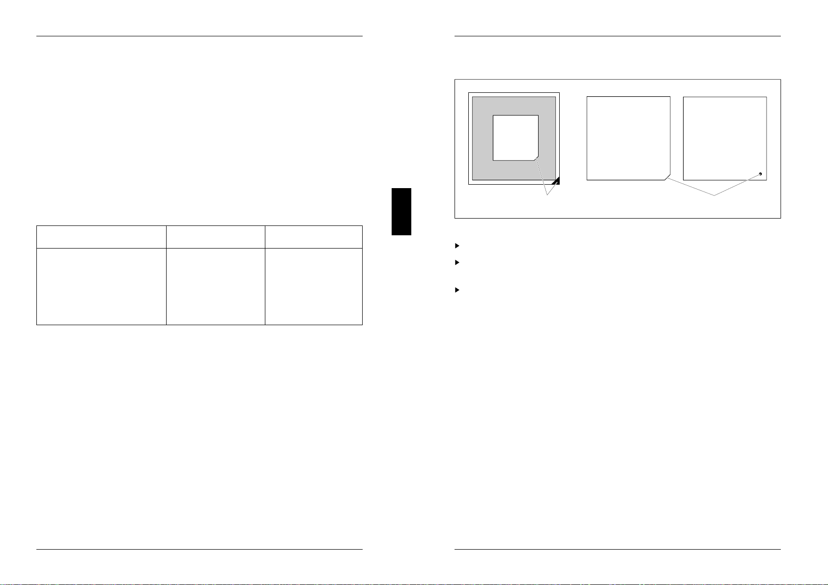
Upgrading
D30
12
1 = Mark on the socket 2 = Mark on the top of the processor
Remove the old processor from the socket.
Insert the new processor in such a way that the mark on the processor matches
the mark on the socket.
Set the jumpers X33 and X180 7-16 according to the inserted processor.
24 A26361-D802-Z121-3-7619
Settings and add-on modules
Main memory
Two locations (X150 and X151) are available on the system board for connecting
memory modules. If you want to remove or insert memory modules you have to
remove the drive carrier (see "Technical Manual" for the PC).
!You may only use quick memory modules (Access time = 70 nsec or less)!
For the memory configuration we recommend the upgrade levels and slots
listed in the table .
Memory configuration memory modules slots
4 Mbyte 1 of 4 Mbyte X150
8 Mbyte 2 of 4 Mbyte each X150 and X151
8 Mbyte 1 of 8 Mbyte X150
12 Mbyte 1 of 8 Mbyte X150 and
1 of 4 Mbyte X151
16 Mbyte 2 of 8 Mbyte each X150 and X151
16 Mbyte 1 of 16 Mbyte X150
24 Mbyte 1 of 16 Mbyte X150 and
1 of 8 Mbyte X151
32 Mbyte 2 of 16 Mbyte each X150 and X151
32 Mbyte 1 of 32 Mbyte X150
X150 = Bank 0; X151 = Bank 1;
A26361-D802-Z121-3-7619 25
Settings and add-on modules
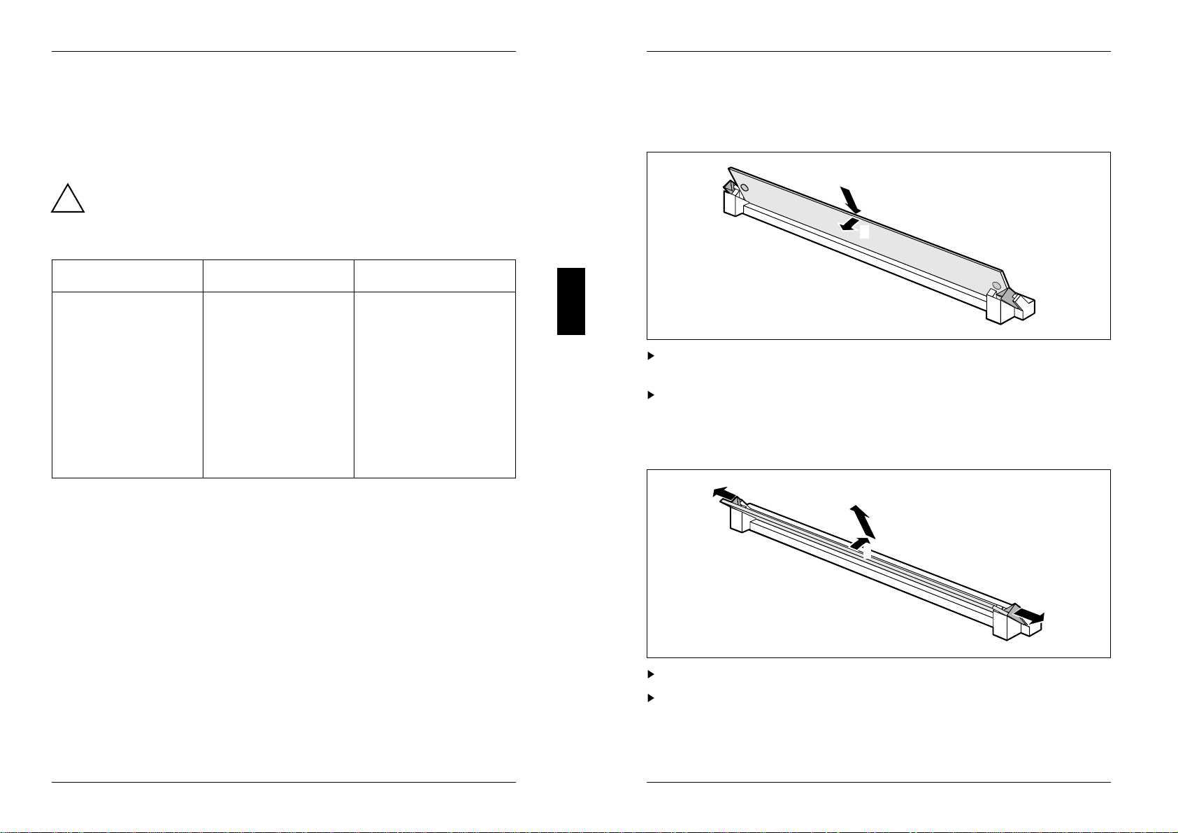
Installing a memory module
If you want to install several memory modules, plug the first memory module into
the slot X150 (Bank 0).
1
2
Insert the memory module at an angle into the appropriate slot (1).
Ensure that the two holes in the memory module line up with the holding pins.
Tilt the module back until it snaps into place (2).
Removing a memory module
1
1
3
2
Force the plastic holders carefully outward at left and right (1).
Tilt the module forward (2) and pull the module off upward (3).
26 A26361-D802-Z121-3-7619

Settings and add-on modules
Second level cache memory
The second level cache memory can be 0 Kbytes or 128 Kbytes in size. There are
5 sockets on the system board (D120, D130 to D133) for incorporating the SRAM
components.
You should set the following in the Setup menu in order to be able to use the
second level cache memory completely:
– Shadow BIOS ROM: SYSTEM AND VIDEO BIOS
– Cache: INTERN AND EXTERN
– Cache Shadow RAM: VIDEO BIOS ONLY
Upgrading
!Information on which SRAM components you can use is available from your
sales office or the customer service.
You may insert only a SRAM component 32Kbit*9, 15 ns into the socket
D120.
You may insert only a SRAM component 32Kbit*8, 20 ns into the sockets
D130 to D133.
Note the location of the SRAM chip when you plug in SRAM chip!
1
2
1 = Mark on socket
2 = Mark on the top of the SRAM component
Insert the SRAM component in such a way that the mark on the SRAM
component matches the position of the mark on the socket.
Set the recommended entries in the Setup menu.
A26361-D802-Z121-3-7619 27

Interface assignment
The assignment of the standard interfaces is described in the technical manual of
the PC (section "Technical data").
Connector X250 for power supply
16
Pin Meaning
1 Power Good
2 +5V
3 +12 V
4 -12 V
5 0 V
6 0 V
Connector X251 for power supply
16
Pin Meaning
1 0 V
2 0 V
3 -5 V
4 + 5 V
5 + 5 V
6 + 5 V
A26361-D802-Z121-3-7619 29
Interface assignment
Connector for external loudspeaker X255
1
4
Pin Meaning
1 +5 V
2 0 V
3 coded
4 external loudspeaker
Connector X258 for indicator
17
6
Pin Signal name
1 System unit ON
2 not used
3 coded
4 not used
5 Reset switch
6 +5 V
7 0 V
8 0 V
9 coded
10 0 V
11 0 V
12 Hard disk drive
30 A26361-D802-Z121-3-7619
This manual suits for next models
1
Table of contents
Other Siemens Nixdorf Motherboard manuals

Siemens Nixdorf
Siemens Nixdorf D931 User manual

Siemens Nixdorf
Siemens Nixdorf Fujitsu D1115 User manual

Siemens Nixdorf
Siemens Nixdorf D969 User manual

Siemens Nixdorf
Siemens Nixdorf D808 User manual

Siemens Nixdorf
Siemens Nixdorf Fujitsu D1160 User manual

Siemens Nixdorf
Siemens Nixdorf D1156 User manual

Siemens Nixdorf
Siemens Nixdorf D1085 User manual

Siemens Nixdorf
Siemens Nixdorf D858 User manual

Siemens Nixdorf
Siemens Nixdorf D756 User manual

Siemens Nixdorf
Siemens Nixdorf D818 User manual


 user manual")
