Siemens Nixdorf D969 User manual

System board D969
Technical Manual

Is there ...
... any technical problem or other
question you need clarified?
Please contact:
• one of our IT Service Shops
• your sales partner
• your sales office
The addresses of your service partners
are contained in the guarantee booklet
or in the service address booklet.
The latest information on our products,
tips, updates, etc., can be found on the
Internet under:
http://www.siemens.com/pc
... anything you want to tell us
about this manual?
Please send us your comments quoting
the order number of the manual.
Siemens AG
User Documentation Department,
ICP CS BS2 OS ID4
Otto-Hahn-Ring 6
D-81730 München

Your training needs?
The Siemens Training Centers offer you a wide range of training courses in
information technology and on IT products and other subjects - onsite near to your
workplace or offsite at one of our training centers.
Let us know your training requirements or request information from us -
the fastest way is via fax under: +49 89 636-42945
Or write to:
Siemens AG
Training Center, Beratungsservice
D-81730 München

System board D969 Techni
c
Dieses Handbuch wurde auf Recycling-Papier gedruckt.
This manual has been printed on recycled paper.
Ce manuel est imprimé sur du papier recyclé.
Este manual ha sido impreso sobre papel reciclado.
Questo manuale è stato stampato su carta da riciclaggio.
Denna handbok är tryckt på recyclingpapper.
Dit handboek werd op recycling-papier gedrukt.
Herausgegeben von/Published by
Siemens AG
D-81730 München
Bestell-Nr./Order No.: A26361-D969-Z120-8-7619
A26361-D969-Z120-8-7619A26361-D969-Z120-8-7619
A26361-D969-Z120-8-7619
Printed in the Federal Republic of Germany
AG 1198 11/98
A26361-D969-Z120-1-7619

System board D969
Technical Manual
Introduction
Important notes
Settin
g
s in BIOS Setup
Settin
g
s with switch bloc
k
Add-on modules
Error messa
g
es
Index
November 1998 edition

Creative is a registered trademark, Sound Blaster 16 and VIBRA 16C are trademarks of
Creative Technology Ltd.
Intel and Pentium are registered trademarks and OverDrive is a trademark of Intel
Corporation, USA.
AMD-K5 is a trademark of Advanced Micro Devices, Inc.
Microsoft, MS, MS-DOS and Windows are registered trademarks of Microsoft Corporation.
PS/2 and OS/2 Warp are registered trademarks of International Business Machines, Inc.
All other trademarks referenced are trademarks or registered trademarks of their respective
owners, whose protected rights are acknowledged.
Copyright ãSiemens AG 1998
All rights, including rights of translation, reproduction by printing, copying or similar methods,
even of parts are reserved.
Offenders will be liable for damages.
All rights, including rights created by patent grant or registration of a utility model or design,
are reserved.
Delivery subject to availability. Right of technical modification reserved.

A26361-D969-Z120-8-7619
Contents
Introduction ........................................................................................................... 1
Notational conventions............................................................................................ 1
Features.................................................................................................................. 2
Interfaces and connectors....................................................................................... 4
Possible screen resolution....................................................................................... 5
Resource table ........................................................................................................ 7
Important notes ..................................................................................................... 9
Settings in BIOS Setup ....................................................................................... 11
Main menu - Making system settings .................................................................... 11
System Time / System Date........................................................................... 12
Diskette A / Diskette B.................................................................................... 12
Hard Disk 1 to Hard Disk 4 - Hard disk drive.................................................. 13
Boot Options .................................................................................................. 16
Video Display ................................................................................................. 18
Base Memory................................................................................................. 18
Extended Memory.......................................................................................... 18
Advanced menu - Making advanced system settings............................................ 19
Cache Memory............................................................................................... 20
Shadow Memory ............................................................................................ 22
Peripheral Configuration - Ports and Controllers............................................ 23
PCI Configuration........................................................................................... 27
Advanced System Configuration.................................................................... 29
Plug & Play O/S.............................................................................................. 31
Reset Configuration Data............................................................................... 31
Large Disk Access Mode - Hard disk access ................................................. 31
Menu Security - Setting up the security features................................................... 32
Setup Password / System Password.............................................................. 32
Set Setup Password....................................................................................... 33
Setup Password Lock..................................................................................... 33
Set System Password.................................................................................... 33
System Password Mode................................................................................. 34
System Load .................................................................................................. 34
Setup Prompt - Setup message ..................................................................... 34
Virus Warning................................................................................................. 35
Diskette Write................................................................................................. 35
Flash Write..................................................................................................... 35
Power On/Off.................................................................................................. 36
Power menu - Setting energy saving functions ..................................................... 39

Contents
A26361-D969-Z120-8-7619
APM - Enabling the APM Interface.................................................................39
Power Management Mode - Extent of energy saving functions......................40
Standby Timeout ............................................................................................40
Suspend Timeout - Suspend mode ................................................................40
Hard Disk Timeout..........................................................................................41
Standby CPU Speed.......................................................................................41
Save To Disk ..................................................................................................41
Wakeup Event - Defining system activities.....................................................43
BIOSFaX menu - modem - quick start functions....................................................44
Receive Mode.................................................................................................44
Ring Count......................................................................................................44
Fax Tone Count..............................................................................................45
Fax Modem Port - Serial port..........................................................................45
Exit menu...............................................................................................................46
Save Changes & Exit - Saving and Exiting.....................................................46
Discard Changes & Exit..................................................................................46
Get Default Values .........................................................................................46
Load Previous Values.....................................................................................46
Save Changes................................................................................................46
Settings with switch block S180.........................................................................47
Clock speed - switch 1, 2, 3 and 4.........................................................................48
Recovering System BIOS - switch 5......................................................................48
Write protection for System BIOS - switch 7..........................................................49
Write protection for floppy disk drive - switch 8......................................................49
Add-on modules ..................................................................................................51
Upgrading main memory........................................................................................52
Replacing the processor........................................................................................54
Upgrading the Second-level cache........................................................................55
Upgrading the video memory.................................................................................56
Connecting an audio board....................................................................................57
Replacing the lithium battery .................................................................................58
Error messages....................................................................................................59
Messages d'erreur ...............................................................................................61
Mensajes de error................................................................................................63
Messagi di errore.................................................................................................65
Felmeddelanden ..................................................................................................67
Foutmeldingen.....................................................................................................69
Index .....................................................................................................................71

A26361-D969-Z120-8-7619 1
Introduction
This description applies for the system board D969 with PCI bus (Peripheral
Component Interconnect).
i
This system board is available in different configuration levels. Depending
on the hardware configuration of your device, it may be that you cannot
find several options in your version of the system board, even though they
are described.
Further information to drivers is provided in the readme files on hard disk or on the
supplied drivers diskettes or on the "Drivers & Utility" CD.
Notational conventions
The meanings of the symbols and fonts used in this manual are as follows:
!Pay particular attention to texts marked with this symbol. Failure to
observe this warning endangers your life, destroys the system, or may
lead to loss of data.
i
This symbol is followed by supplementary information, remarks and tips.
Ê Texts which follow this symbol describe activities that must be performed in the
order shown.
ËThis symbol means that you must enter a blank space at this point.
Ú
ÚÚ
ÚThis symbol means that you must press the Enter key.
Texts in this typeface are screen outputs from the PC.
Texts in this bold typeface are the entries you make via the keyboard.
Texts in italics indicate commands or menu item.
"Quotation marks" indicate names of chapters and terms that are being
emphasized.

Introduction Features
2A26361-D969-Z120-8-7619
Features
• ATX system board
• 64-bit processor Intel Pentium with 16 Kbytes internal cache (first-level cache,
8 Kbytes data cache, 8 Kbytes code cache) or
OverDrive processor for Pentium
or
• AMD-K5
• Memory configuration on the system board: 8 to 128 Mbyte (FPM or EDO)
• Error recognition and correction via ECC / Parity
• Second-level cache on the system board: 0, 256 or 512 Kbytes (PBSRAM)
• 256 Kbytes Flash BIOS
• 3 PCI, 2 ISA slots and 1 ISA/PCI slot (shared)
• PCI bus
• IDE hard disk controller connected to PCI bus for up to four IDE drives
(e.g. IDE hard disk drives, ATAPI CD ROM drive)
• Real-time clock/calendar with integrated battery backup
• Floppy disk controller (up to 2.88 Mbytes format)
• Parallel interface (ECP- and EPP-compatible)
• 2 Serial interfaces
• PS/2 mouse port
• PS/2 keyboard port
• Security functions

Features Introduction
A26361-D969-Z120-8-7619 3
Optional Component
• Video connector
• Screen controller connected to PCI bus, graphics processor Cirrus Logic CL-
GD5446 with Windows accelerator and 1 Mbyte or 2 Mbytes DRAM video
memory
• Audio controller on ISA-BUS (Creative VIBRA 16C; 16 bit; compatible with
Sound Blaster 16, MPU401, Multimedia PC and Multimedia PC II; Stereo-FM
synthesizer YAMAHA OPL3)
• USB (Universal Serial Bus)
• Energy saving functions
• Connector for feature connector, loudspeaker
• Connector for remote-on (fax/modem board), chipcard reader and infrared
interface
• Connector for CD-line in, wavetable module, Game/Midi, voice modem, AUX-
in
• Microphone connector (via supplementary board)
• Audio port (line in) (via supplementary board)
• Headphone connector (via supplementary board)
i
The microphone connector, audio port and headphone connector are
connected via a common plug (Game/Midi / Audio) on the system board.
Introduction Interfaces and connectors
4A26361-D969-Z120-8-7619
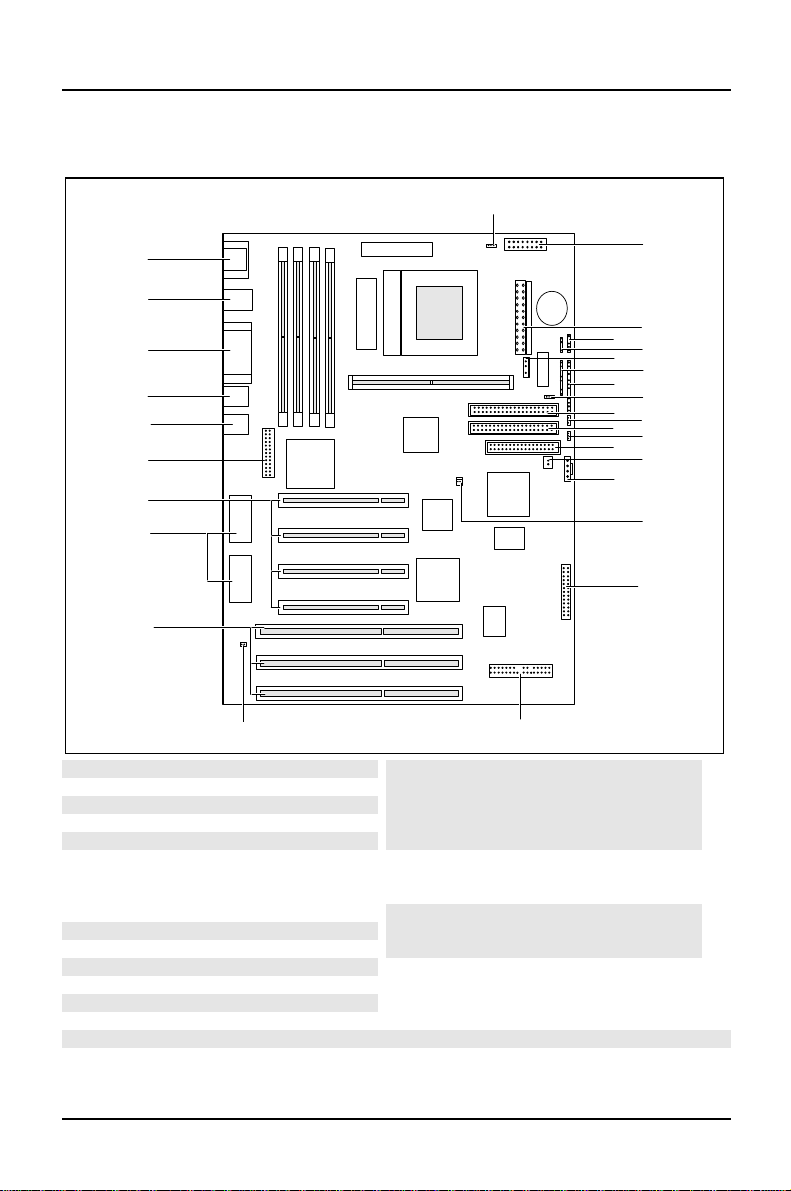
Interfaces and connectors
29
1
2
34
56
78
910
11 12
13 14
15
16
17
1819
20
22
23
24
25
26
27
28
21
1 = Chipcard reade
r
2 = Power supply
3 = infrared interface
4 = External loudspeake
r
5 = Soft-off power supply
6 = LED indicators in front panel
7 = LED indicators in front panel
8 = SCSI-LEDs
9 = IDE drives 3 and 4 (secondary)
10 = Voice modem
11 = IDE drives 1 and 2 (primary)
12 = AUX IN
13 = Floppy disk drive
14 = Remote on via fax/modem
15 = CD Line in
16 = Power on switch
17 = Wavetable board
18 = Game/Midi / Audio
19 = I2C connecto
r
20 = ISA slots 1-3
21 = Socket for video memory
22 = PCI slots 1-4
23 = Feature board
24 = Video connecto
r
25 = USB
26 = Parallel port
27 = PS/2 mouse and keyboard port
28 = Serial interface1/2
29 = Fan
The connectors marked do not have to be present on the system board.

Possible screen resolution Introduction
A26361-D969-Z120-8-7619 5
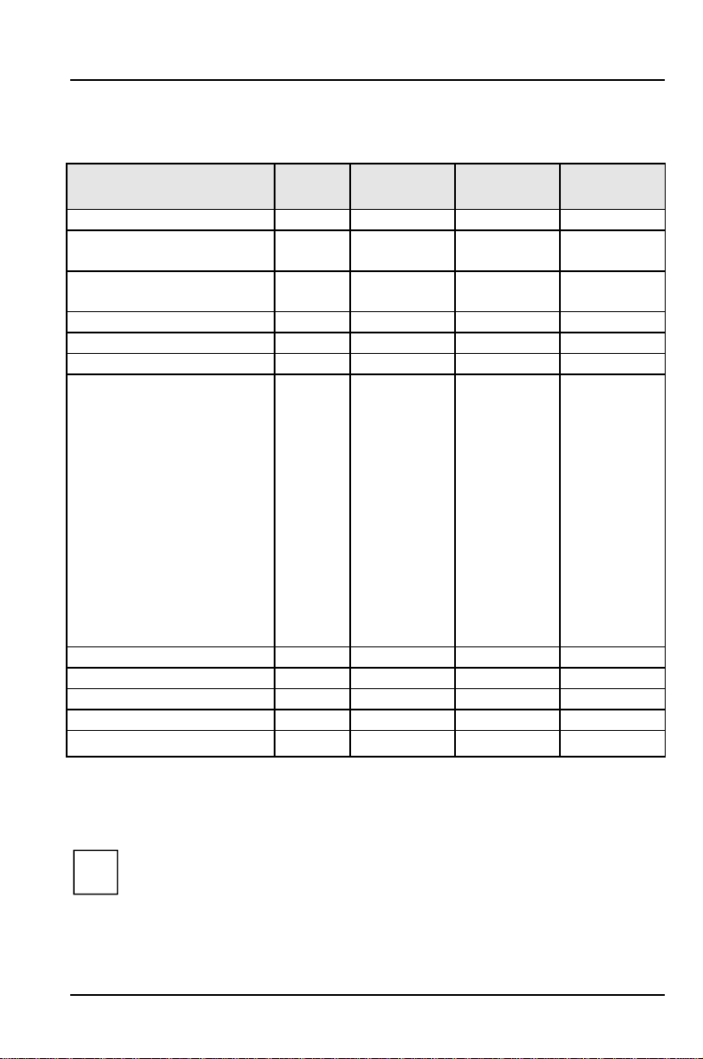
Possible screen resolution
Depending on the operating system used the screen resolutions in the following
table refer to the screen controller on the system board. If you are using an
external screen controller, you will find details of supported screen resolutions in
the Operating Manual or Technical Manual supplied with the controller.
You can set the screen resolution under Windows 95 by selecting Control Panel -
Display -Settings.
You can set the screen resolution under MS-DOS using the SET-VGA program.
Introduction Possible screen resolution
6A26361-D969-Z120-8-7619
Screen
resolution Refresh rate (Hz) Horizontal-
rate (kHz) ** Max. number of
colors
640x350 70 31,5 16
640x350 84 38 16
640x480 60 31,5 16777216
640x480 75 37,5 16777216
640x480 85 43,4 16777216
640x480 100 50,6 16777216
720x400 70 31,5 16
720x400 84 38 16
800x600 60 38 65536
800x600 60 38 16777216
800x600 72 48 65536
800x600 72 48 16777216
800x600 75 47 65536
800x600 75 47 16777216
800x600 85 53,7 65536
800x600 85 53,7 16777216
800x600 100 63 65536
800x600 100 63 16777216
1024x768 87 interlaced 36 256
1024x768 87 interlaced 36 65536
1024x768 60 48,4 256
1024x768 60 48,4 65536
1024x768 75 60 256
1024x768 75 60 65536
1024x768 85 68,7 256 *
1024x768 100 81 256 *
1280x1024 87 interlaced 49 16
1280x1024 87 interlaced 49 256
1280x1024 60 63,7 256 *
1280x1024 75 80,4 256 *
* no 16 color mode
** The horizontal rate values may have a tolerance range of ± 0.3 kHz.
The values marked are only available with a 2-Mbytes video memory.
Resource table Introduction
A26361-D969-Z120-8-7619 7
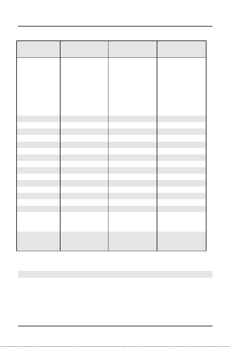
Resource table
assigned
IRQ possible IRQ Possible
Address Possible
DMA
Keyboard IRQ1
Serial port COM2 / IrDA IRQ3 02F8, 03F8
02E8, 03E8
Serial interface COM1 / Chip
card reader IRQ4 03F8, 02F8
03E8, 02E8
Floppy disk drive controller IRQ6 DMA2
Parallel interface LPT1 IRQ7 IRQ5, IRQ7 0278, 0378 DMA1, DMA3
RTC IRQ8
Audio controller
Joystick:
Base address:
MPU 401:
Adlib:
IRQ5, IRQ7,
IRQ9, IRQ10
0200-0207
0220-022F
0240-024F
0260-026F
0280-028F
0300-0301
0330-0331
0338-038B
DMA1, DMA3,
DMA5, DMA7
USB controller IRQ11
Mouse controller IRQ12
Numeric processor IRQ13
IDE controller 1 IRQ14
IDE controller 2 IRQ15
"assigned IRQ" = interrupts assigned as shipped
"Possible IRQ" = these interrupts can be used for your particular application
"Possible address" = this address can be used for your particular application
"Possible DMA" = these DMAs can be used for your particular application
i
Please note that a resource cannot be used by two applications at the
same time.

A26361-D969-Z120-8-7619 9
Important notes
Store this manual close to the device. If you pass on the device to third parties,
you should also pass on this manual.
!Be sure to read this page carefully and note the information before you
open the device.
You cannot access the components of the system board without first
opening the device. How to dismantle and reassemble the device is
described in the Operating Manual accompanying the device.
Please note the information provided in the chapter "Safety" in the
Operating Manual of the device.
Incorrect replacement of the lithium battery may lead to a risk of
explosion. It is therefore essential to observe the instructions in the
chapter "Add-on modules" - "Replacing the lithium battery".
The lithium battery must be replaced with an identical battery or a
battery type recommended by the manufacturer (CR2032).
Do not throw lithium batteries into the trashcan. It must be disposed of in
accordance with local regulations concerning special waste.
ADVARSEL
!Lithiumbatteri - Eksplosionsfare ved fejlagtig håndtering. Udskiftning må
kun ske med batteri af samme fabrikat og type. Lever det brugte batteri
tilbage til leverandøren.
ADVARSEL
!Eksplosjonsfare ved feilaktig skifte av batteri. Benytt samme batteritype
eller en tilsvarende type anbefalt av apparatfabrikanten. Brukte batterier
kasseres i henhold til fabrikantens instruksjoner.
VARNING
!Eksplosionsfara vid felaktigt batteribyte. Använd samma batterityp eller en
ekvivalent typ som rekommenderas av apparattillverkarenfabrikanten.
Kassera använt batteri enligt fabrikantens instruktion.
VAROITUS
!Paristo voi räjähtää, jos se on virheellisesti asennettu. Vaihda paristo
ainoastaan laitevalmistajan suosittelemaan tyyppiin. Hävitäkäytetty
paristo valmistajan ohjeiden mukaisesti.

Important notes
10 A26361-D969-Z120-8-7619
The shipped version of this board complies with the requirements
of the EEC directive 89/336/EEC "Electromagnetic compatibility".
Compliance was tested in a typical PC configuration.
When installing the board, refer to the specific installation
information in the Operating Manual or Technical Manual of the
receiving device.
Connecting cables for peripherals must be adequately insulated to avoid
interference.
!Components can become very hot during operation. Make sure you do
not touch components when making extensions to the system board.
There is a danger of burns!
i
The warranty expires if the device is damaged during the installation or
replacement of system expansions. Information on which system
expansions you can use is available from your sales office or the
customer service.
Boards with electrostatic sensitive devices (ESD) may be identified by labels.
When you handle boards fitted with ESDs, you must observe the following points
under all circumstances:
• You must always discharge yourself (e.g. by touching a grounded object)
before working.
• The equipment and tools you use must be free of static charges.
• Pull out the power plug before inserting or pulling out boards containing ESDs.
• Always hold boards with ESDs by their edges.
• Never touch pins or conductors on boards fitted with ESDs.

A26361-D969-Z120-8-7619 11
Settings in BIOS Setup
The BIOS Setup menu allows you to set your hardware configuration and system
functions. In addition, the BIOS Setup displays technical information on the PC's
configuration.
When it is supplied, the PC is set to factory default settings which you can alter in
the BIOS Setup menus. You can change these settings in BIOS Setup. Any changes
you make take effect as soon as you save the settings and quit the BIOS Setup.
The Operating Manual describes how to call the BIOS Setup and change menu
entries.
You can select the following settings in the BIOS Setup:
Main - system functions
Advanced - advanced system configuration
Security - security features
Power - power-management features
BIOSFaX - quick start functions
Exit - save and quit
i
The various menus are described below with all setting options. Since the
setting options depend on your PC's hardware configuration, some of
them may not be offered in the BIOS setup.
Main menu - Making system settings
In the Main menu you can set up the following:
• Time (in the field marked System Time)
• Date (in the field marked System Date)
• Floppy disk drive (in the field marked Diskette A or Diskette B)
• Hard disk drive (in the submenus of Hard Disk)
• System boot (in the submenus of Boot Options)
• Display device (in the field marked Video Display)

Settings in BIOS Setup Main - system functions
12 A26361-D969-Z120-8-7619
Phoenix BIOS Setup
M
ain Advanced Security Power BIOSFaX Exit
System Time: [07:42:19]
System Date: [08/11/1995]
Diskette A: [1.4M]
Diskette B: [None]
ÊHard Disk 1: 1 Gbyte
ÊHard Disk 2: None
ÊHard Disk 3: None
ÊHard Disk 4: None
ÊBoot Options
Video Display: [EGA/VGA]
Base Memory: 640K
Extended Memory: 7M
Item Specific Help
——————————————————————
F1 Help ↑↓ Select Item -/+ Change Values F9 Setup Defaults
ESC Exit ← → Select Menu Enter Execute Command F7 Previous Values
Example for Main menu
System Time / System Date
The System Time field and the System Date field show the time and date respectively
according to the PC. The time is shown in the format hh:mm:ss
(hours:minutes:seconds) and the date is shown in the format mm/dd/yyyy
(month/day/year).
!If the settings in the System Time and System Date fields are frequently
wrong when you power up the computer, the lithium battery is dead.
Change the battery as described in "Add-on modules“-"Replacing the
lithium battery“).
Diskette A / Diskette B
These two fields are used to specify the type of floppy disk drive installed.
360K, 720K, 1.2M, 1.4M,2.8M
The entry depends on the floppy disk drive installed.
(Default entry Diskette A : 1.4M).
None A floppy disk drive is not installed.
(Default entry for Diskette B: 1.2M).
Table of contents
Other Siemens Nixdorf Motherboard manuals

Siemens Nixdorf
Siemens Nixdorf D1025 User manual

Siemens Nixdorf
Siemens Nixdorf D808 User manual

Siemens Nixdorf
Siemens Nixdorf D802-C User manual

Siemens Nixdorf
Siemens Nixdorf D1111 User manual

Siemens Nixdorf
Siemens Nixdorf D1156 User manual

Siemens Nixdorf
Siemens Nixdorf D824 User manual

Siemens Nixdorf
Siemens Nixdorf Fujitsu D1160 User manual

Siemens Nixdorf
Siemens Nixdorf D756 User manual

Siemens Nixdorf
Siemens Nixdorf D818 User manual

Siemens Nixdorf
Siemens Nixdorf D1042 User manual


