Siemens Nixdorf D808 User manual

PCPC
System board D808
EISA/PCI
The Intel Inside Logo is
a registered trademark
Technical Manual of Intel Corporation
Dieses Handbuch wurde auf Recycling-Papier gedruckt.
This manual has been printed on recycled paper.
Ce manuel est imprimé sur du papier recyclé.
Este manual ha sido impreso sobre papel reciclado.
Questo manuale è stato stampato su carta da riciclaggio.
Denna handbok är tryckt på recyclingpapper.
Dit handboek werd op recycling-papier gedrukt.
Herausgegeben von/Published by
Siemens Nixdorf Informationssysteme AG
33094 Paderborn
81730 München
Bestell-Nr./Order No.: A26361-D808-Z121-1-7619
Printed in the Federal Republic of Germany
AG 1094 10/94
A26361-D808-Z121-1-7619

Is there ...
... any technical problem or other ... anything you want to tell us
question you need clarified? about this manual?
Please send us your comments quoting
Please contact: the order number of the manual.
– one of our IT Service Shops
– your sales partner Siemens Nixdorf Informationssysteme AG
– your sales office User Documentation Department
BS2000 QM2, Otto-Hahn-Ring 6,
You will find the addresses of the 81730 München, Germany
IT Service Shops in the enclosed
warranty coupon booklet. Fax: (0 89) 6 36-4 04 43

Introduction
Important notes
Settings
System board D808
EISA/PCI Add-on modules
Interface assignment
Interrupt and DMA
Error messages
Technical Manual
Index
October 1994 edition
Would you like to know more ...
... about this product
... or about another aspect of information technology training?
Our Training Centers will be glad to help.
Siemens Nixdorf has Training Centers at strategic
locations in Germany and more than 20 countries worldwide.
Please write to:
Siemens Nixdorf
International Training Support
Oldbury, Bracknell, Berkshire RG12 8FZ
United Kingdom
or call
Ron Johnson, Hounslow
Tel.: .44 344 850 990
Fax.: .44 344 850 991
Adaptec is a registered trademark of Adaptec Inc.
Intel is a registered trademark and Pentium is trademark of Intel Corporation.
Microsoft, MS and MS-DOS are registered trademarks and Windows is a trademark of
Microsoft Corporation.
PS/2 is a registered trademark of International Business Machines, Inc.
UNIX is a registered trademark of UNIX System Laboratories.
Copyright Siemens Nixdorf Informationssysteme AG 1994
The reproduction, transmission or use of this document or its contents is not permitted without
express written authority.
Offenders will be liable for damages
All rights, including rights created by patent grant or registration of a utility model or design,
are reserved.
Delivery subject to availability.
Right of technical modification reserved.
Contents
Introduction 1
Explanation of symbols 1
Features 2
Important notes 5
Notes on software 6
Settings 7
Setup menu 7
System Configuration page 8
The System Security Options page 11
Additional System Options page 17
PCI Device Configuration page 21
Additional Hard Disk Options page 23
Switch block S500 26
Add-on modules 29
Main memory 29
Installing memory modules 30
Removing memory modules 30
Interface pinouts, interrupts and DMA 31
Connector X800/X801 and X811: Power supply 31
Connector X805: Indicators at the front 32
Connector X806: Fan 32
Connector X809: Loudspeaker 33
Connector X810: Control signals for power supply 33
Parallel interface 34
Pinout in SPP mode 34
Pinout in EPP mode 35
Pinout in ECP mode 35
Serial interface 36
PS/2 mouse port 37
PS/2 keyboard port 37
Interrupt Request Levels and DMA channels 38
A26361-D808-Z121-1-7619
Contents
Error messages 39
Index 51
A26361-D808-Z121-1-7619

Introduction
This technical manual describes the system board D808.
Explanation of symbols
The meanings of the symbols and fonts used in this manual are as follows:
!Pay particular attention to texts marked with this symbol. Failure to observe
this warning endangers your life, destroys the system, or may lead to loss of
data.
This symbol is followed by supplementary information, remarks and tips.
i
Texts which follow this symbol describe activities that must be performed in the
order shown.
This symbol means that you must enter a blank space at this point.
↵ This symbol means that you must press the Enter key.
Texts in this typeface are screen outputs from the PC.
Texts in this bold typeface are the entries you make via the keyboard.
Texts in italics indicate commands or menu items.
"Quotation marks" indicate highlighted text and names of chapters.
A26361-D808-Z121-1-7619 1
Introduction
Features
– Pentium processor (into ZIF socket): 60 MHz, 16 Kbyte cache, coprocessor
– Mercury EISA-PCI chipset
– 64 bit data bus
– 256 Kbyte second level cache
– 8 to 192 Mbyte main memory (3 banks)
– Flash memory (128 Kbyte)
– 36-bit SIM modules (PS/2 modules)
– Socket for real-time clock with 114 Byte CMOS RAM memory and battery
– Floppy disk controller (up to 2,88 Mbyte)
– Fast IDE hard disk controller on the PCI bus
– 3 PCI slots
– 1 ISA slot
– 4 Master-capable EISA slots
– Connector for floppy disk drive
– 2 connectors for IDE hard disk drives (2 x 2 IDE hard disks can be connected)
– Connector for external loudspeaker
– Parallel interface (ECP and EPP compatible)
– Two serial interfaces
– Mouse port (PS/2)
– Keyboard port (PS/2
– Piezoelectric busser
– Switch bank for user settings
– Password protection
2A26361-D808-Z121-1-7619
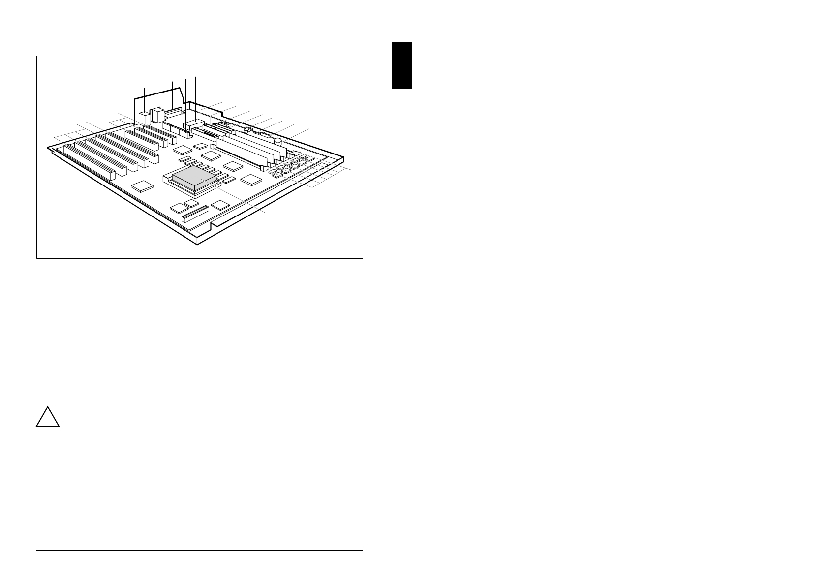
Introduction
1
2
3
4
5
6
7
8
17
18
9
10
1112 13
14
15
16
12345
678
1 = slots 1 to 4 (EISA) 10 = Connector for IDE
2 = slot 5 (ISA) hard disk drive (primary)
3 = slots 6 to 8 (PCI) 11 = DIP switch S500
4 = Mouse and keyboard interface 12 = Connector for standard
5 = Serial interfaces Ser1 and Ser2 floppy disk drive
6 = Parallel interface 13 = Connector for fan
7 = Connector for standard- 14 = Connector for external loudspeaker
power supply and for 15 = Connector for indicator
3,3 V power supply (system unit on, hard disk)
8 = Real-time clock (RTC) 16 = Piezoelectric busser
9 = Connector for IDE 17 = 6 sockets for SIM modules
hard disk drive (secondary) 18 = Pentium processor
!Only short boards can be inserted in the following slots:
– slot 4 (EISA)
– slot 5 (ISA)
– slot 6 (PCI)
– slot 8 (PCI)
The other slots can accommodate long or short boards.
A26361-D808-Z121-1-7619 3
Important notes
!Please note the information provided in the chapter "Important notes" in the
Operating Manual of the PC.
The lithium battery on the board may only be replaced by specialist
technicians. There is a danger of explosion if this is not done properly.
The lithium battery must be replaced with an identical battery or a battery
type recommended by the manufacturer.
The lithium battery must be disposed of in accordance with local regulations
on the disposal of special refuse.
Be sure to read this page carefully and note the information before you
open the PC.
ADVARSEL
!Lithiumbatteri - Eksplosionsfare ved fejlagtig håndtering. Udskiftning må kun
ske med batteri af samme fabrikat og type. Lever det brugte batteri tilbage
til leverandøren.
ADVARSEL
!Eksplosjonsfare ved feilaktig skifte av batteri. Benytt samme batteritype eller
en tilsvarende type anbefalt av apparatfabrikanten. Brukte batterier
kasseres i henhold til fabrikantens instruksjoner.
VARNING
!Eksplosionsfara vid felaktigt batteribyte. Använd samma batterityp eller en
ekvivalent typ som rekommenderas av apparattillverkarenfabrikanten.
Kassera använt batteri enligt fabrikantens instruktion.
VAROITUS
!Paristo voi räjähtää, jos se on virheellisesti asennettu. Vaihda paristo
ainoastaan laitevalmistajan suosittelemaan tyyppiin. Hävitä käytetty paristo
valmistajan ohjeiden mukaisesti.
A26361-D808-Z121-1-7619 5
Important notes
Modules with electrostatic sensitive devices (ESD) may be identified by labels.
When you handle modules fitted with ESDs, you must observe the following points
under all circumstances:
– When you handle modules fitted with ESDs, you must always discharge yourself
(e.g. by touching a grounded object) before working.
– The equipment and tools you use must be free of static charges.
– Pull out the power plug before inserting or pulling out modules containing ESDs.
– Always hold modules with ESDs by their edges.
– Never touch pins or conductors on modules fitted with ESDs.
Notes on software
Program with time loops
Problems can occur with programs in which time loops have been implemented
through software loops. This applies in particular to older programs which were
written for 8 MHz processors.
SCO-UNIX on devices with Pentium or OverDrive processor
If you use the processor mentioned above, the Adaptec-SCSI controller AHA 1740
cannot be addressed under SCO-UNIX 3.2.4 and ODT 2.0.
To solve this problem, you can order from SCO an SLS (Support Level
Supplement) consisting of 3 floppy disks, or contact one of our IT Service Shops.
The problem no longer exists in the new releases of SCO-UNIX 3.2.4.2 and
ODT 2.1.
There will be no support for older versions (SCO-UNIX versions lower than 3.2.4
and ODT versions lower than 2.0).
6A26361-D808-Z121-1-7619

Settings
You can make settings in the setup menu or using the switch block on the system
board.
Setup menu
The setup menu displays settings and technical information on the PC's
configuration. The Operating Manual describes how to call the setup menu and
change menu entries. Pressing the function key F1 provides help information on
each entry field.
The setup menu consists of the following screen pages:
System Configuration
System Security Options
Additional System Options
PCI Device Configuration
Additional Hard Disk Options
A26361-D808-Z121-1-7619 7
Settings
System Configuration page
CMOS Setup
System Configuration
---------------------------------------------------------------------------
Time (hh:mm:ss) 08:38:27 Date (mm/dd/yy) 08/13/1993
Diskette A: 1.4M
Diskette B: NONE
Cyl Hd Pre LZ Sec Mbyte
Hard Disk 1: NONE
Hard Disk 2: NONE
Hard Disk 3: NONE
Hard Disk 4: NONE
Base Memory: 640K Video Display: EGA/VGA
Extended Memory: 15360K Speed Select: HIGH
Error Halt: HALT ON ALL ERRORS
---------------------------------------------------------------------------
<F1> Help <F8> System info <F10> Store CMOS <Esc> Exit Page
<...> Edit field <↑↓←→> Next field <PgUp> Next page <Ctrl> ... 01
Example of the System Configuration page
Time
Date Time and Date show the time and date respectively according to the PC. The
time is shown in the format hh:mm:ss (hours:minutes:seconds) and the date is
shown in the format mm/dd/yy (month/day/year).
!If the settings in the Time and Date fields are frequently wrong when
you power up the computer, the lithium battery is dead. Change the
battery as described in "Add-on modules - Replacing the lithium
battery").
Diskette A
Diskette B
specify the type of floppy disk drive installed. The possible settings are: 360K,
1.2M, 720K, 1.4M, 2.8M or NONE.
Default entry for Diskette A:
3 1/2-inch floppy drive 1.4M
5 1/4-inch floppy drive 1.2M
Default entry for Diskette B: NONE
8A26361-D808-Z121-1-7619

Settings
Hard Disk 1
Hard Disk 2
Hard Disk 3
Hard Disk 4
indicate the types of hard disks installed. The entries here may possibly not
match the information printed on the hard disk drive by the manufacturer.
The maximum transfer rate of two IDE drives connected to the same
connector is determined by the slower of the two. Fast hard disks should
therefore be connected to the first IDE connector and identified as Hard
Disk 1 or Hard Disk 2; slower hard disks should be connected to the second
IDE connector and identified as Hard Disk 3 or Hard Disk 4.
Possible settings: 1through 43,AUTO or NONE.
Do not alter the default settings unless you mount a different hard disk
idrive. If the wrong hard disk type is entered, the operating system
cannot be loaded.
Special entries for the hard disk type:
Entry for SCSI hard disks: NONE
Entry for ESDI hard disks: 1
1through 39
The hard disk parameters (cylinders, heads, etc.) for types 1 through 39
are preset.
40 through 43
The hard disk parameters (cylinders, heads, etc.) for types 40 through 43
are user-defined and are entered at the keyboard.
Examples of user-defined entries (IDE drives)
Size Cyl Hd Pre* Lz* Sec Mbytes
120 Mbytes: 762 8 NONE 762 39 121
170 Mbytes: 904 8 NONE 904 46 170
210 Mbytes: 683 16 NONE 683 38 212
340 Mbytes: 904 16 NONE 904 46 340
540 Mbytes: 1048 16 NONE 1048 63 542
1 Gbyte: 2079 16 NONE 2079 63 1080
* These values are preset and cannot be modified.
A26361-D808-Z121-1-7619 9
Settings
AUTO
If the hard disk supports this mode, the setup menu reads the hard disk
parameters from the disk itself and sets them automatically. You do not
need to select the parameters yourself.
NONE
The computer either has no hard disk or is fitted with a SCSI hard disk.
Default entry for Hard Disk 1:
depends on the type of hard disk installed
Default entry for Hard Disk 2,3,4:NONE
Base Memory
indicates the size of the available base memory below 1 Mbyte.
512K
A module needs the memory between 512 and 640 Kbytes.
640K
The memory is used by the system board.
Default entry: 640K
Extended Memory
indicates the size of the memory above 1 Mbyte. You can reduce the size of
extended memory if necessary.
Video Display
specifies the type of monitor connected.
Possible entries are: EGA/VGA, COLOR 40, COLOR 80, MONO.
Default entry: EGA/VGA
Speed Select
specifies the system speed set at system startup. You might, for example,
need to select a slower speed for certain software programs that use
programmed time loops.
HIGH
Full system speed
LOW
Reduced system speed.
Default entry: HIGH
10 A26361-D808-Z121-1-7619

Settings
Error Halt
specifies which errors the self-test should not report. The default setting
should only be changed if required by special applications.
HALT ON ALL ERRORS
The self-test reports all errors it encounters.
NO KEYBOARD ERROR HALT
The self-test ignores keyboard errors.
NO DISK ERROR HALT
The self-test ignores floppy disk and hard disk errors.
NO KEYBOARD OR DISK HALT
The self-test ignores keyboard, floppy disk and hard disk errors.
NO HALT ON ANY ERRORS
The self-test ignores all errors.
Default entry: HALT ON ALL ERRORS
The System Security Options page
CMOS Setup
System Security Options
---------------------------------------------------------------------------
Time (hh:mm:ss) 08:38:27 Date (mm/dd/yy) 08/13/1993
System Load: STANDARD
Security Features: DISABLED
Serial 1: COM1 (3F8h) Diskette Write: ENABLED
Serial 2: COM2 (2F8h) Diskette Ctrlr: ENABLED
Parallel: LPT1 (378h) Setup Prompt: ENABLED
Par Mode: PRINTER Quick Load: DISABLED
Virus Warning: DISABLED
Mouse Ctrlr: ENABLED
Flash Write: ENABLED
---------------------------------------------------------------------------
<F1> Help <F8> System info <F10> Store CMOS <Esc> Exit Page
<+ -> Select item <↑↓←→> Next field <PgUp> Next page <Ctrl> ... 02
Example of the System Security Options page
A26361-D808-Z121-1-7619 11
Settings
Time / Date
Time shows the current time and Date shows the current date according to
the PC.
System Load
allows you to disable booting from floppy disk or swap the drive letters
assigned to the floppy disk drives.
STANDARD
The operating system can be loaded from floppy disk or hard disk.
NONSTANDARD
System start-up is controlled by the operating system (terminal
emulation).
DISKETTE LOCK
The operating system can only be loaded from hard disk.
DISKETTE SWAP
Drives A and B are switched.
Default entry: STANDARD
Security Features
allows you to define a password to prevent access to the data in your PC.
DISABLED
No passwords are in effect.
SYSTEM AND Setup LOCK
The setup menu and the operating system are protected by passwords.
SETUP LOCK
The setup menu is protected by a password.
KEYBOARD AND Setup LOCK
The setup menu is protected and the keyboard and the mouse are locked
by passwords.
CHANGE PASSWORD
This option is only displayed if a password has already been defined. It
enables you to alter the password.
Default entry: DISABLED
12 A26361-D808-Z121-1-7619

Settings
Serial 1
selects the address and the interrupt used to access serial interface 1.
COM1 (3F8h)
Serial interface 1 is set to the address 3F8h and IRQ4 (edge-triggered).
COM3 (3E8h)
Serial interface 1 is set to the address 3E8h and IRQ4 (edge-triggered).
DISABLED
Serial interface 1 is disabled.
Default entry: COM1 (3F8h)
Serial 2
selects the address and the interrupt used to access serial interface 2.
COM2 (2F8h)
Serial interface 2 is set to the address 2F8h and IRQ3 (edge-triggered).
COM4 (2E8h)
Serial interface 2 is set to the address 2E8h and IRQ3 (edge-triggered).
DISABLED
Serial interface 2 is disabled.
Default entry: COM2 (2F8h)
Parallel
selects the address and the interrupt used to access the parallel interface.
LPT1 (378h)
The parallel interface is set to the address 378h and IRQ7.
LPT3 (3BCh)
The parallel interface is set to the address 3BCh and IRQ7.
DISABLED
The parallel interface is disabled.
Default entry: LPT1 (378h)
A26361-D808-Z121-1-7619 13
Settings
Par Mode
specifies whether the parallel interface is to be used as a bidirectional
input/output port or just as an output port.
In addition LPT1 can be configured for ECP, EPP, and ECP and EPP transfer
modes, which allow transfer rates of 2 and 2.4 Mbytes/s. These modes will
only work with peripheral devices which also support them.
PRINTER
The port functions as an output port only.
BIDIRECTION
Data can be transferred in both directions across the port.
EPP
Enhanced Parallel Port transfer mode.
ECP
Enhanced Capability Port transfer mode.
ECP AND EPP
Enhanced Capability and Enhanced Parallel Port transfer mode.
Default entry: PRINTER
Mouse Ctrlr
enables and disables the built-in mouse controller on the system board.
ENABLED
The mouse controller is enabled (IRQ12 used).
DISABLED
The mouse controller is disabled (IRQ12 free).
Default entry: ENABLED
Flash Write
write-protects the flash BIOS.
ENABLED
The flash BIOS can be written or deleted, provided switch 3 on the system
board is set to OPEN.
DISABLED
The flash BIOS cannot be written. The BIOS cannot be flash-upgraded
from floppy disk.
Default entry: ENABLED
14 A26361-D808-Z121-1-7619

Settings
Diskette Write
This field is used to enable and disable floppy disk write-protection.
ENABLED
Floppy disks can be read, written or deleted, provided switch 6 of the
switch block S500 on the system board is set to OPEN.
DISABLED
Floppy disks can only be read.
Default entry: ENABLED
Diskette Ctrlr
enables and disables the built-in floppy disk controller on the system board.
ENABLED
The floppy disk controller is enabled.
DISABLED
The floppy disk controller is disabled.
Default entry: ENABLED
Setup Prompt
specifies whether the F2 FOR SETUP prompt is displayed when the PC is
started.
ENABLED
The F2 FOR SETUP prompt is displayed when the system is started.
DISABLED
The prompt is not displayed.
Default entry: ENABLED
A26361-D808-Z121-1-7619 15
Settings
Quick Load
allows you to shorten the duration of the self-test and speed up system start-
up. If you choose the quick self-test option, only a minimum memory test is
carried out.
ENABLED
The quick self-test is enabled.
DISABLED
The normal self-test is carried out.
Default entry: DISABLED
Virus Warning
enables and disables a check of the boot sector on the bootable hard disk for
changes since the last system start-up. If changes are detected and the
cause is unknown, you should run an appropriate virus checker to check for
a virus.
ENABLED
If the boot sector has been modified since the system last booted (e.g,. a
new operating system version has been installed or the hard disk has
been infected by a virus), an on-screen warning appears.
!!! HARD DISK WARNING !!!
Boot sector has been modified.
Confirm the new boot sector in SETUP,
and run a virus scan program.
This warning is re-displayed each time you restart the system until you
acknowledge the message with CONFIRM or you disable the function by
setting this field to DISABLED.
CONFIRM
By selecting this option, you indicate to the system that the modification to
the boot sector was intentional (e.g., you have installed a new operating
system version).
DISABLED
Boot sectors are not checked.
Default entry: DISABLED
16 A26361-D808-Z121-1-7619

Settings
Additional System Options page
CMOS Setup
Additional System Options
---------------------------------------------------------------------------
Time (hh:mm:ss) 08:38:27 Date (mm/dd/yy) 08/13/1993
System BIOS: 128K
Shadow BIOS ROM: SYSTEM AND VIDEO BIOS
C800 CC00 D000 D400 D800 DC00
Shadow Adaptor ROM: NO NO NO NO NO NO
Cache: INTERN AND EXTERN
Cache Mode: WRITE BACK
Cache BIOS ROM: VIDEO BIOS ONLY
C800 CC00 D000 D400 D800 DC00
Cache Adaptor ROM: NO NO NO NO NO NO
---------------------------------------------------------------------------
<F1> Help <F8> System info <F10> Store CMOS <Esc> Exit Page
<+ -> Select item <↑↓←→> Next field <PgUp> Next page <Ctrl> ... 03
Example of the Additional System Options page
Time / Date
Time shows the current time and Date shows the current date according to
the PC.
System BIOS
can make available a ROM address area of 32 Kbytes for requests via the
ISA/PCI bus (e.g., SCSI BIOS).
Entry Memory area / location
96K E8000H - FFFFFH / system board
128K E0000H - FFFFFH / system board
96K
A 96-Kbyte area is reserved for the system BIOS.
A 32-Kbyte area (E0000H - E7FFFH) is available for requests via the
ISA/PCI bus.
128K
A 128-Kbyte area is reserved for the system BIOS.
Default entry: 128K
A26361-D808-Z121-1-7619 17
Settings
Shadow BIOS ROM
allows you to copy the video BIOS to fast RAM in addition to the system
BIOS at system start-up. Copying the BIOS to RAM increases CPU
performance.
SHADOW BIOS ROM memory areas:
Entry RAM area used
SYSTEM BIOS ONLY E8000H - FFFFFH
SYSTEM AND VIDEO BIOS C0000H - C7FFFH/E8000H - FFFFFH
SYSTEM AND VIDEO BIOS
The system BIOS and the video BIOS are both copied to RAM area
C0000H - C7FFFH and F0000H - FFFFFH.
SYSTEM BIOS ONLY
Only the system BIOS is copied to RAM area E8000H - FFFFFH.
Default entry: SYSTEM AND VIDEO BIOS
Shadow Adaptor ROM
allows you to copy 16-Kbytes adaptor ROMs to RAM. If ROM code executes
from RAM it increases your PC's performance. The ROM of PCI adaptors is
always copied to RAM, regardless of the setting in this field.
NOThe relevant ROM area is not copied to RAM.
YES
The relevant ROM area is copied to RAM.
Default entry: NO
18 A26361-D808-Z121-1-7619

Settings
Cache
specifies which cache memory the CPU should use. Cache memory greatly
increases performance. If the system runs too fast for certain older software,
you can slow it down by disabling the cache (DISABLED).
INTERN ONLY
Only the internal cache is enabled.
INTERN AND EXTERN
The internal cache and the external cache are enabled.
DISABLED
Both the internal cache and the external cache are disabled. All cache-
related settings are then without effect.
Default entry: INTERN AND EXTERN
Cache Mode
Condition: Cache must be enabled.
Cache Mode sets the mode in which the CPU uses the cache; write
operations to the cache are carried out either in write-back mode or write-
through mode. In write-back mode the CPU writes information to the cache
and the information is only written to main memory if necessary. Memory and
cache contents are not identical. In write-through mode the processor writes
the information to the cache and to main memory. The contents of memory
and cache are identical.
WRITE BACK
The cache works in write-back mode.
WRITE THROUGH
The cache works in write-through mode.
Default entry: WRITE BACK
A26361-D808-Z121-1-7619 19
Settings
Cache BIOS ROM
Condition: Cache must be enabled.
Cache BIOS ROM lets you specify BIOS ROM areas that should also be
mapped to the cache in addition to main memory.
SYSTEM BIOS ONLY
The system BIOS is mapped to the cache.
VIDEO BIOS ONLY
The video BIOS is mapped to the cache.
SYSTEM AND VIDEO BIOS
The system BIOS and the video BIOS are mapped to the cache.
DISABLED
BIOS ROM areas are not mapped to the cache.
Default entry: SYSTEM AND VIDEO BIOS
Cache Adaptor ROM
Condition: Cache must be enabled.
Cache Adaptor ROM allows you to specify whether the relevant 16-Kbyte ROM
area should be mapped to the cache. Mapping the ROM area to RAM
increases system performance.
NOThe relevant ROM area is not mapped to the cache.
YES
The relevant ROM area is mapped to the cache.
Default entry: NO
20 A26361-D808-Z121-1-7619

Settings
PCI Device Configuration page
CMOS Setup
PCI Device Configuration
---------------------------------------------------------------------------
Time (hh:mm:ss) 08:38:27 Date (mm/dd/yy) 08/13/1993
Memory Base Address: 44000000h Color Palette Snoop: DISABLED
I/O Base Address: D000h Parity Checking: ENABLED
INTA# INTB# INTC# INTD#
PCI Interrupt Mapping: AUTO AUTO AUTO AUTO
---------------------------------------------------------------------------
<F1> Help <F8> System info <F10> Store CMOS <Esc> Exit Page
<...> Select item <↑↓←→> Next field <PgUp> Next page <Ctrl> ... 04
Example of the PCI Device Configuration page
Time / Date
Time shows the current time and Date shows the current date according to
the PC.
Memory Base Address
shows the base address used to map memory areas of PCI boards.
I/O Base Address
shows the base address for PCI adapter input/output operations.
A26361-D808-Z121-1-7619 21
Settings
Color Palette Snoop
specifies whether setting of the color palette is to be available on the ISA
bus.
ENABLED
Setting of the color palette is available simultaneously on the PCI bus and
the ISA bus. This setting can be of relevance when operating video or
multimedia boards on the ISA bus.
DISABLED
Setting of the color palette is only available on the PCI bus.
Default entry: DISABLED
Parity Checking
specifies whether the PCI bus is to be parity-checked.
ENABLED
A parity check is performed on the PCI bus.
DISABLED
No parity check is performed on the PCI bus.
Default entry: ENABLED
PCI Interrupt Mapping
specifies which PCI interrupt is to be mapped to which ISA interrupt. With
multifunctional PCI adaptor boards you may use all PCI interrupts.
The PCI interrupts INTA# and INTB# are normally assigned as follows:
Slot 1 = INTA#, slot 2 = INTB#
Possible entries: NONE, AUTO, 3, 4, 5, 6, 7, 9, 10, 11, 12, 14, 15
Default entry: INTA# AUTO
INTB# AUTO
INTC# AUTO
INTD# AUTO
You can obtain information on assigned ISA interrupts on PCI boards
iby pressing the function key F8 which brings up the System
Information screen.
22 A26361-D808-Z121-1-7619

Settings
Additional Hard Disk Options page
CMOS Setup
Additional Hard Disk Options
---------------------------------------------------------------------------
Time (hh:mm:ss) 08:38:27 Date (mm/dd/yy) 08/13/1993
Hard Disk Ctrlr: ENABLED
Transfer Mode LBA Translation Power Down
Hard Disk 1: STANDARD DISABLED DISABLED
Hard Disk 2: STANDARD DISABLED DISABLED
Hard Disk 3: STANDARD DISABLED DISABLED
Hard Disk 4: STANDARD DISABLED DISABLED
---------------------------------------------------------------------------
<F1> Help <F8> System info <F10> Store CMOS <Esc> Exit Page
<+ -> Select item <↑↓←→> Next field <PgUp> Next page <Ctrl> ... 05
Example of the Additional Hard Disk Options page
Time / Date
Time shows the current time and Date shows the current date according to
the PC.
Hard Disk Ctrlr
enables and disables the built-in IDE hard disk controller. The associated
interrupt will only be available if no hard disk is physically connected.
ENABLED
The IDE hard disk controller is enabled.
DISABLED
The IDE hard disk controller is disabled.
Default entry: ENABLED
A26361-D808-Z121-1-7619 23
Settings
Hard Disk 1: Transfer Mode
Hard Disk 2: Transfer Mode
Hard Disk 3: Transfer Mode
Hard Disk 4: Transfer Mode
specifies the transfer rate for the IDE hard disks.
STANDARD
The system transfers 512 bytes per interrupt
AUTO SELECT
If fast hard disks are installed, the highest possible transfer rate is
selected. If the hard disk supports this mode, the setup menu prompts for
the maximum number of blocks to be transferred per interrupt. The
maximum is 32 blocks of 512 bytes each. In addition, the hard disk's PIO
modes 0 through 4 (Processor Input Output modes) are used.
8K BLOCK XFER
Eight Kbytes are transferred per interrupt.
Default entry: STANDARD
Hard Disk 1: LBA Translation
Hard Disk 2: LBA Translation
Hard Disk 3: LBA Translation
Hard Disk 4: LBA Translation
enables and disables the LBA (Logical Block Addressing) mode. LBA mode
allows you to install and use hard disks with a capacity of more than 528
Mbytes. If a hard disk supports LBA mode, you can use its full capacity.
!You may only use IDE drives in the LBA mode selected when they
were set up. In other words, if you set up a hard disk with LBA mode
DISABLED, you may only operate the hard disk with LBA mode
DISABLED.
DISABLED
The BIOS uses the hard disk parameters and supports a maximum
capacity of 528 Mbytes.
24 A26361-D808-Z121-1-7619

Settings
AUTO SELECT
If the hard disk supports LBA and it has a capacity of more than 528
Mbytes, the BIOS translates the hard disk parameters, allowing the disk's
full capacity to be used.
If the hard disk does not support LBA, its parameters are not translated.
Default entry: DISABLED
Hard Disk 1: Power Down
Hard Disk 2: Power Down
Hard Disk 3: Power Down
Hard Disk 4: Power Down
specifies the period of hard disk inactivity after which the hard disk's motor is
power down. The next hard disk read or write operation powers up the hard
disk again automatically.
The hard disk requires roughly 15 seconds to run up.
Possible entries: DISABLED, 5 min, 10 min, 15 min
Default entry: DISABLED (the hard disk does not power down)
A26361-D808-Z121-1-7619 25
Settings
Switch block S500
The 8 switches of the DIP switch S500 serve to set various board functions. The
list below shows switch numbers and associated functions.
Switch 1: Recovery mode
Places the PC in recovery mode. This mode enables the PC to boot from the
floppy disk drive via a second, non-erasable rudimentary BIOS after an error
BIOS update (BIOS flash). The BIOS update can be repeated after
rebooting.
Switch open
BIOS operates in normal mode.
Switch closed
BIOS operates in recovery mode.
Default setting: Switch open
Switch 2: Password protection
Switch open
Setup menu can only be called if the correct password is entered.
Switch closed
Setup menu can be called irrespective of the assigned password.
Default setting: Switch open
Switch 3: freely definable
The position of the switch can be queried via the port 0C91H (bit 2).
Switch open
Bit 2 is set to 1.
Switch closed
Bit 2 is set to 0.
Default setting: Switch open
26 A26361-D808-Z121-1-7619

Settings
Switch 4: freely definable
The position of the switch can be queried via the port 0C91H (bit 3).
Switch open
Bit 3 is set to 1.
Switch closed
Bit 3 is set to 0.
Default setting: Switch open
Switch 5: Flash EPROM Write Protection
Switch open
The Flash EPROM can be written to.
Switch closed
The Flash EPROM cannot be written to.
Default setting: Switch open
Switch 6: Floppy Disk Write Protect
Switch open
Floppy disks may be read, written to or deleted.
Switch closed
Floppy disks may only be read.
Default setting: Switch open
Floppy disks can be read in any switch setting.
Switch 7: Reserved for manufacturer
Default setting: Switch open
Do not change the default setting!
Switch 8: Manufacturing Test
Switch open
The PC operates in normal mode.
Switch closed
The PC runs through the tests of the POST routines of the BIOS in an
endless loop. (POST = Power-On Self Test)
Default setting: Switch open
A26361-D808-Z121-1-7619 27
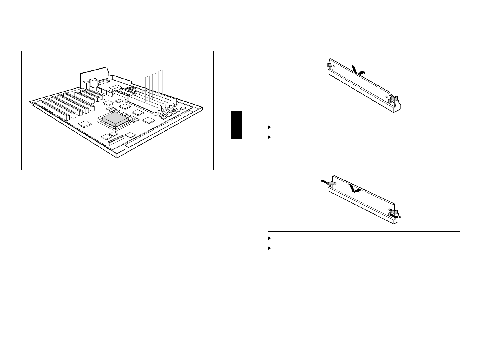
Add-on modules
1
4
1234
678
5
3
2
1
1 = memory bank 1 3 = memory bank 3
2 = memory bank 2
Main memory
The system board has 6 sockets for memory modules (SIMM, Single Inline
Memory Module / PS/2 modules), which are divided into 3 banks with two sockets
each. Memory modules have a capacity of 4, 8, 16 and 32 Mbyte. A memory bank
must always be fully occupied and equipped with memory modules of the same
capacity. Thus, a memory capacity of 8, 16, 32 or 64 Mbyte is possible for each
memory bank, which permits a maximum memory expansion of 192 Mbyte. The
size of the memory modules may vary between memory banks. The order of the 3
memory banks is not relevant. There may be empty memory banks between
occupied memory banks.
A26361-D808-Z121-1-7619 29
Add-on modules
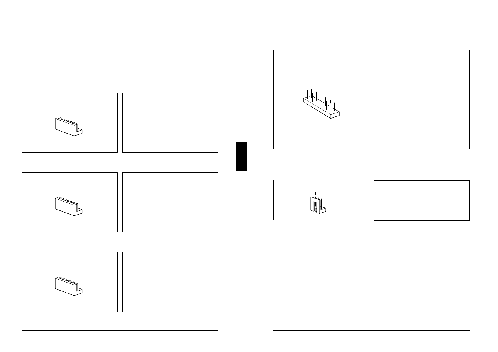
Installing memory modules
1
2
Insert the memory module at an angle into the appropriate slot (1).
Tilt the module back until it snaps into place (2).
Removing memory modules
32
1
1
Force the plastic holders carefully outward at left and right (1).
Tilt the module forward (2) and pull the module off upward (3).
30 A26361-D808-Z121-1-7619
Interface pinouts, interrupts and DMA
Connector X800/X801 and X811: Power supply
Connector X800
16
Pin Meaning
1 Power Good
2 + 5 V
3 + 12 V
4 - 12 V
5 0 V
6 0 V
Connector X801
16
Pin Meaning
1 0 V
2 0 V
3 - 5 V
4 + 5 V
5 + 5 V
6 + 5 V
Connector X811
16
Pin Meaning
1 0 V
2 0 V
3 0 V
4 + 3,3 V
5 + 3,3 V
6 + 3,3 V
A26361-D808-Z121-1-7619 31
Interface pinouts, interrupts and DMA
Connector X805: Indicators at the front
1
7
12
6
Pin Signal
1 + 5 V via 330 Ohm-R
2 free
3 coded
4 free
5 Indicator: System ON
6 + 5 V via 330 Ohm-R
7 0 V
8 0 V
9 coded
10 0 V
11 0 V
12 Indicator: Hard disk
Connector X806: Fan
1
3
Pin Meaning
1 0 V
2 + 12 V
3 free
32 A26361-D808-Z121-1-7619
Table of contents
Other Siemens Nixdorf Motherboard manuals

Siemens Nixdorf
Siemens Nixdorf D1042 User manual

Siemens Nixdorf
Siemens Nixdorf D802-C User manual

Siemens Nixdorf
Siemens Nixdorf D969 User manual

Siemens Nixdorf
Siemens Nixdorf D1085 User manual

Siemens Nixdorf
Siemens Nixdorf Fujitsu D1115 User manual

Siemens Nixdorf
Siemens Nixdorf D931 User manual

Siemens Nixdorf
Siemens Nixdorf D818 User manual

Siemens Nixdorf
Siemens Nixdorf D824 User manual

Siemens Nixdorf
Siemens Nixdorf D1156 User manual

Siemens Nixdorf
Siemens Nixdorf D756 User manual


