Siemens Nixdorf Fujitsu D1115 User manual


Is there ...
... any technical problem or other
question you need clarified?
Please contact:
• Our Hotline:
Mo-Fr: 8 a.m. - 6 p.m.
Sat: 9 a.m. - 2 p.m.
Tel.: ++49 (0) 180 3777 005
• your sales outlet
The latest information on our products, tips, updates, etc., can be found on the Internet under:
http://www.fujitsu-siemens.com


! "
# $
%&
'( ) *
+,&- ,.
' *
/* 0122 01&22
A26361-D1115-Z180-1-7619

System Board D1115
Additional Technical Manual
En
g
lish
December 1999 edition

Copyright Fujitsu Siemens Computers GmbH 1999
Intel, Pentium and Celeron are registered trademarks and MMX and OverDrive are
trademarks of Intel Corporation, USA.
Microsoft, MS, MS-DOS and Windows are registered trademarks of Microsoft Corporation.
PS/2 and OS/2 Warp are registered trademarks of International Business Machines, Inc.
All other trademarks referenced are trademarks or registered trademarks of their respective
owners, whose protected rights are acknowledged.
All rights, including rights of translation, reproduction by printing, copying or similar methods,
even of parts are reserved.
Offenders will be liable for damages.
All rights, including rights created by patent grant or registration of a utility model or design,
are reserved. Delivery subject to availability.
Right of technical modification reserved.

A26361-D1115-Z180-5-7619 English - 1
Contents
Introduction....................................................................................................................................... 1
Features ........................................................................................................................................... 1
Mechanics ........................................................................................................................................ 3
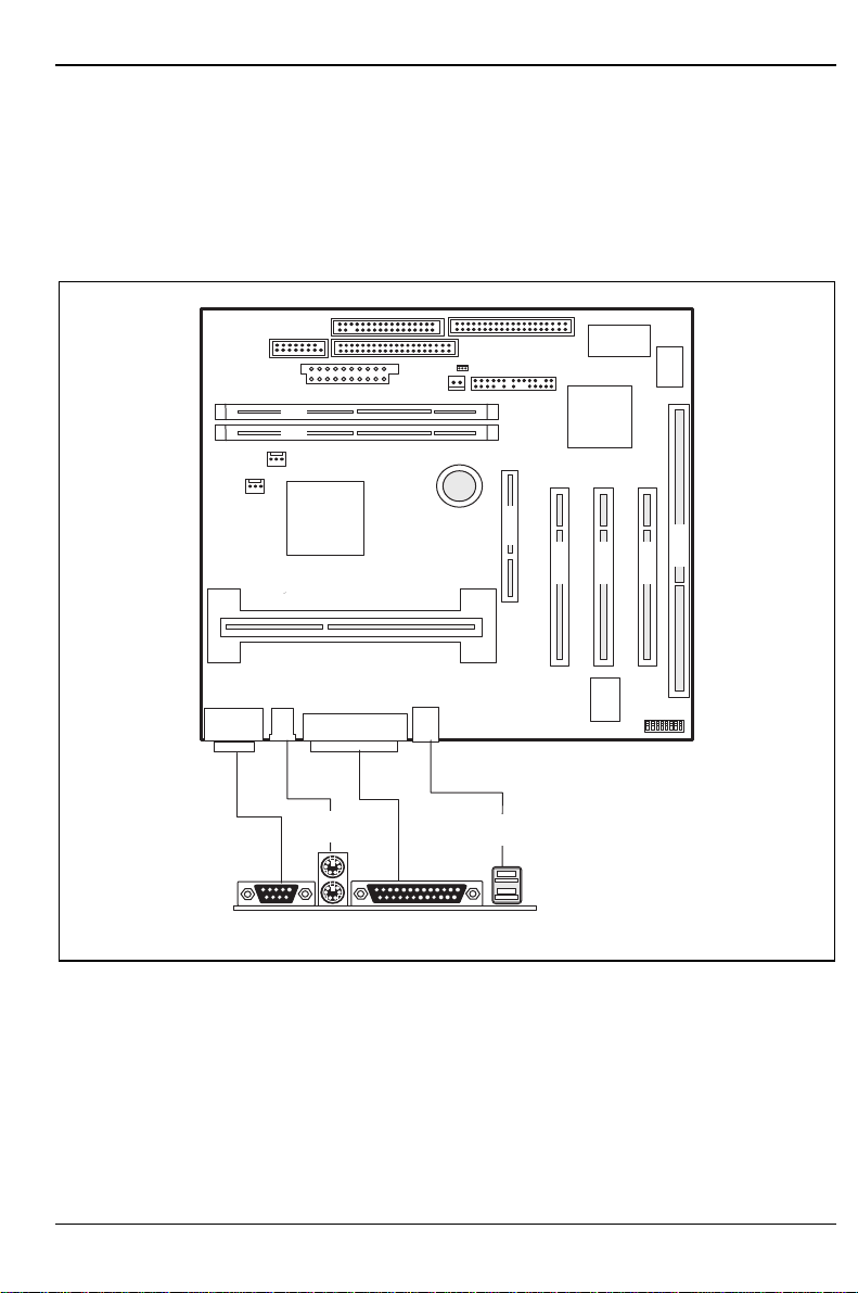
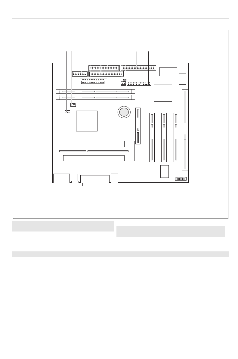
Connectors and Jumpers.......................................................................................................... 5
CPU Fan connector........................................................................................................... 5
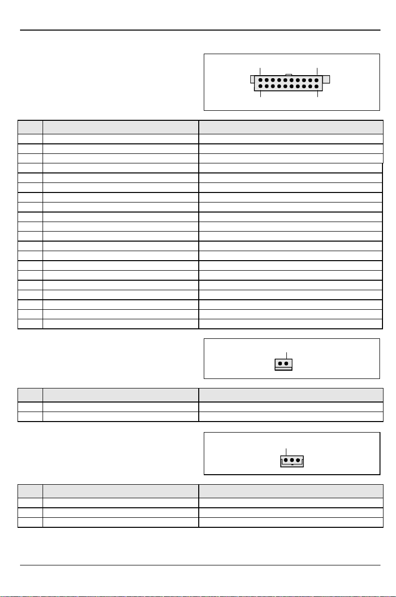
Internal serial (COM2) port (external via wire).................................................................. 5
Power supply ATX connector............................................................................................ 6
Power on switch connector (ON/OFF switch).................................................................... 6
Wake on LAN (WOL) connector........................................................................................ 6
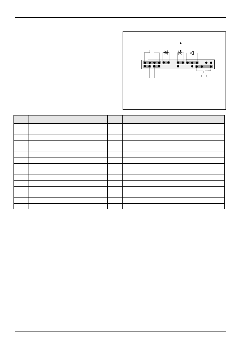
Front panel connector (version 1)...................................................................................... 7
Front panel connector (version 2)...................................................................................... 8
Configuration............................................................................................................................. 9
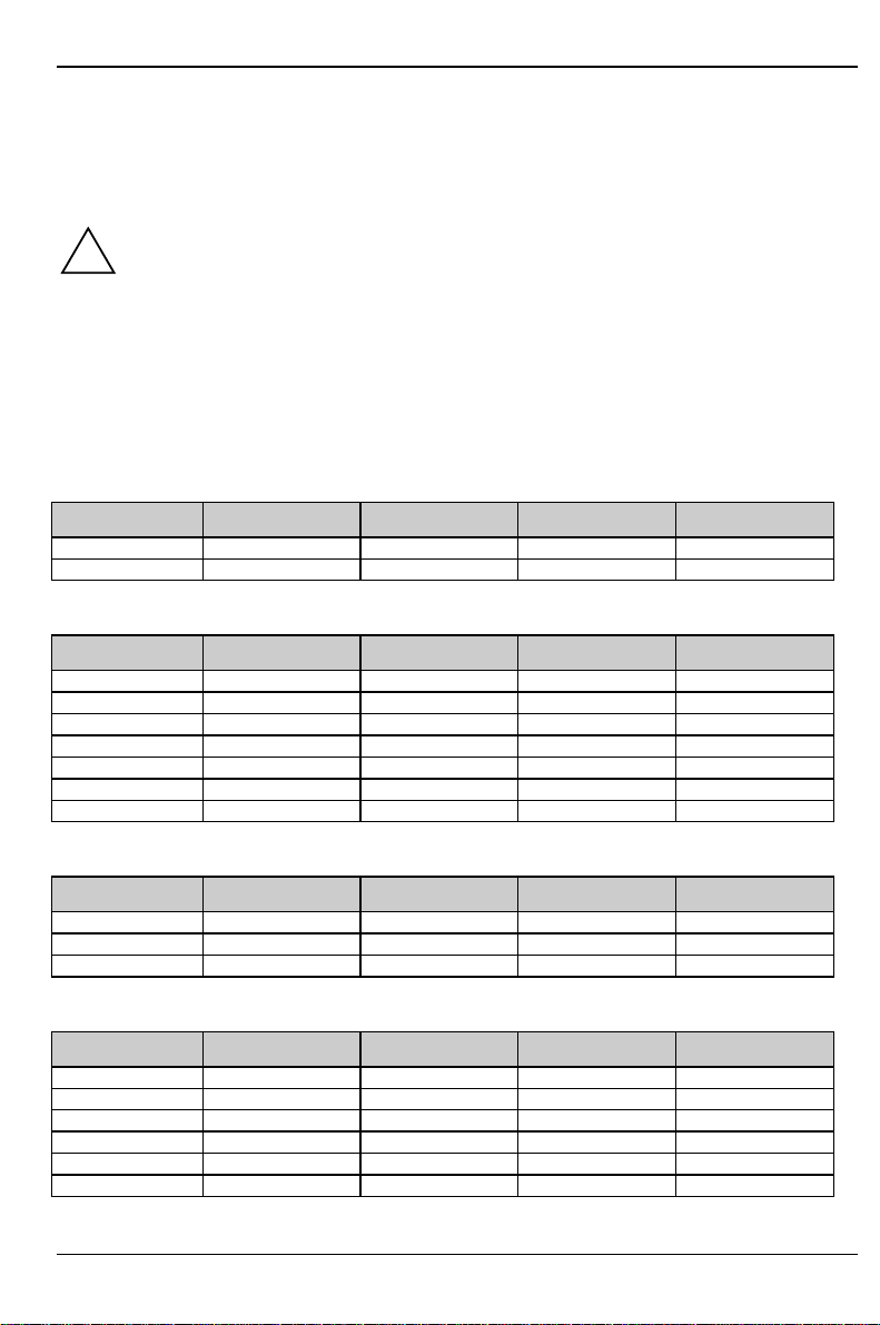
Clock frequency........................................................................................................................ 9
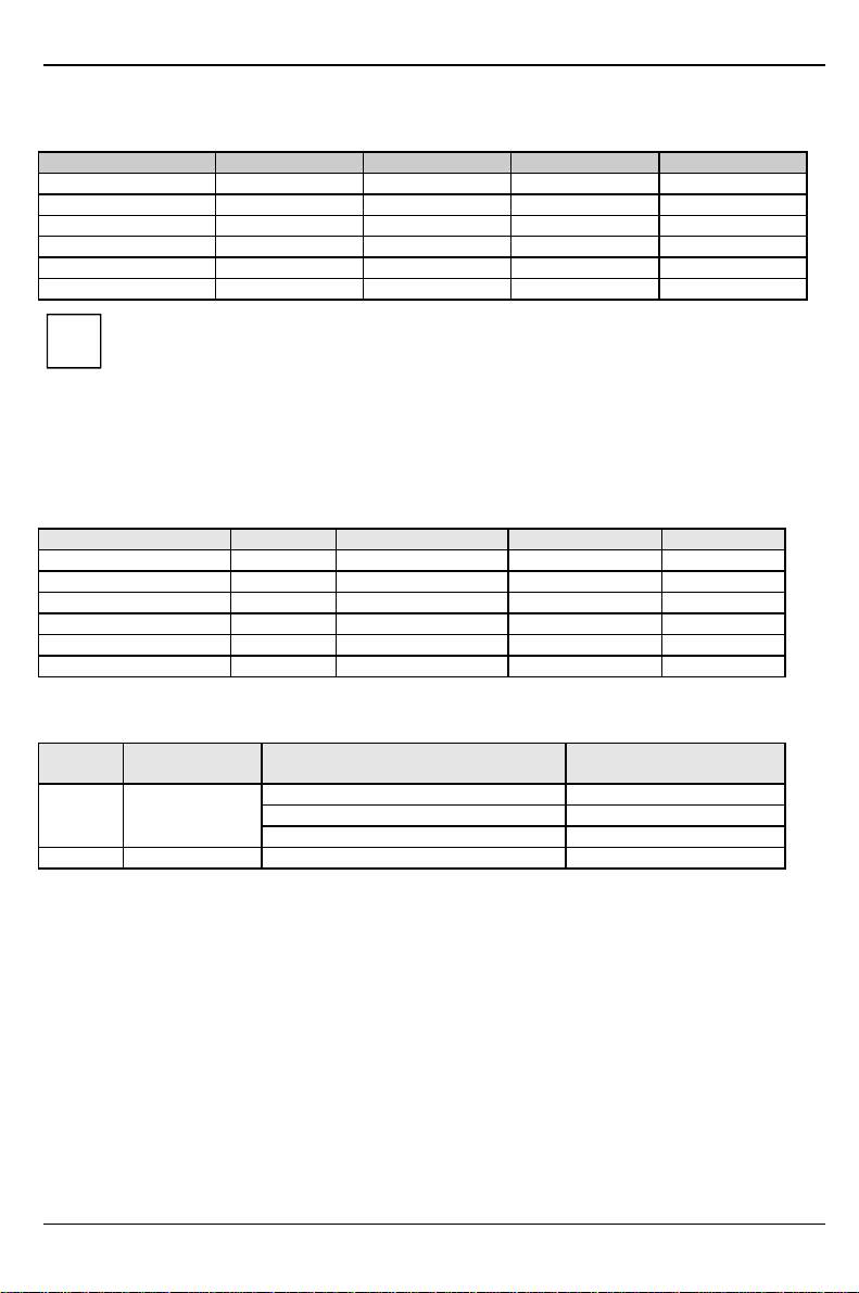
Functions controlled by the switch block......................................................................... 10
Power...................................................................................................................................... 10
Power requirement.......................................................................................................... 10
Power loadability............................................................................................................. 10
Installing drivers.............................................................................................................................. 11
Upgrades........................................................................................................................................ 11
Main memory.......................................................................................................................... 11
Troubleshooting.............................................................................................................................. 12
Message BIOS update............................................................................................................ 12
The screen stays blank........................................................................................................... 12


A26361-D1115-Z180-5-7619 English - 1
Introduction
iThis system board is available in different confi
g
uration levels. Dependin
g
on the
hardware confi
g
uration of your device, it may be that you cannot find several options in
your version of the system board, even though they are described.
You may find further information e. g. in the complete Technical Manual for the system board and in
the description "BIOS Setup".
Further information to drivers is provided on the supplied drivers diskettes or on the "Drivers &
Utility" or "ServerStart" CD. For detailed information please look at chapter "Installing drivers and
utilities".
Features
This table shows an assembly version of this system board as example.
Function Version
F1x G1x
Processor Pentium II or Celeron Pentium II or Celeron
Max. CPU Frequency 450 MHz 500 MHz
Chipset 440 BX 440 ZX
DIMM sockets 2 2
Main memory up to 512 Mbyte 256 Mbyte
ISA slots 0 0
PCI slots 2 2
ISA/PCI shared 1 1
AGP Port 1 1
System monitorin
g
- - - -
Thermal Mana
g
ement - - - -
Wake On LAN (WOL) - - - -
Keyboard On - - - -
IrDA - - - -
Chipcard Reader - - - -
Save to Disk X X
Save to RAM - - - -
IAPC - - - -

Features
2 - English A26361-D1115-Z180-5-7619
!Computer mainboards and components contain very delicate IC chips. To protect
them a
g
ainst dama
g
e caused from electric static, you have to follow some
precautions:
• Unplug your computer when you work inside.
• Hold components by the edge, don't touch their leads.
• Use a grounded wrist strap.
Place the mainboard and the components on a
g
rounded antistatic pad whenever
you work outside the computer.
Once you have installed the system board, you should remove the battery
protection (i.e. the thin plastic plate between battery and contact spring).

Mechanics
A26361-D1115-Z180-5-7619 English - 3
Mechanics
Layout
µ-ATX 9,6" x 8'' (243,84 mm x 203,2 mm)
Some of the following connectors are optional and may therefore not be included on your
mainboard.
21
IS A
P C I 2
PCI 1
P C I 3
AG P
S lo t 1
41 36
25
1 = Serial port 1
2 = PS/2 mouse port
3 = PS/2 keyboard port
4 = Parallel interface
5 = USB connection 2
6 = USB connection 1

Mechanics
4 - English A26361-D1115-Z180-5-7619
21
IS A
P C I 2
PCI 1
P C I 3
AG P
S lo t 1
12 34567
8910
1 = Fan (e. g. for the processor)
2 = Fan (e. g. for the processor)
3 = Serial port 2
4 = Power supply
5 = IDE drives 3 and 4 (secondary)
6 = Floppy disk drive
7 = ON/OFF switch
8 = Wake On LAN (WOL)
9 = IDE drives 1 and 2 (primary)
10 = Front panel connector
The components and connectors marked do not have to be present on the system board.

Mechanics
A26361-D1115-Z180-5-7619 English - 5
Connectors and Jumpers
!Some of the following connectors are optional!
CPU Fan connector
1
Pin Signal Notes
1 GND
2 Fan power supply
3 Not connected
Internal serial (COM2) port (external
via wire)
1
2
Pin Signal Notes
1 DCD 2 (low asserted)
2 DSR 2 (low asserted)
3 SIN 2 (hi
g
h asserted)
4 RTS 2 (low asserted)
5 SOUT 2 (hi
g
h asserted)
6 CTS 2 (low asserted)
7 DTR 2 (low asserted)
8 PC_ON_Strobe
9 GND
10 VCC Auxiliary
11 EXT SMI (low asserted)
12 VCC
13 RESETDRV (hi
g
h asserted)
14 GND
15 GND
16 Key

Mechanics
6 - English A26361-D1115-Z180-5-7619
Power supply ATX connector
10
20
1
11
Pin Signal Notes
1 +3.3 V
2 +3.3 V
3 GND
4 +5 V
5 GND
6 +5 V
7 GND
8 Power
g
ood (hi
g
h asserted)
9 +5 V Auxiliary
10 +12 V
11 +3.3 V
12 -12 V
13 GND
14 PS on (low asserted)
15 GND
16 GND
17 GND
18 -5 V
19 +5 V
20 +5 V
Power on switch connector (ON/OFF
switch)
1
Pin Signal Notes
1 GND
2 Power on pulse (low asserted)
Wake on LAN (WOL) connector 1
Pin Signal Notes
1 +5 V Auxiliary
2 GND
3 Wake pulse (hi
g
h asserted)

Mechanics
A26361-D1115-Z180-5-7619 English - 7
Front panel connector (version 1)
1
2
Reset adapter1) HD-LED2)
2) Cable is not included in the deliver
y
scope.
3) The same interface.
1) Reset adapter from 4pin female to 2pin male.
Power On LED2)
SCSI LED Input 3)
2) Speaker2)
Messa
g
e LED2)
Pin Signal Pin Signal
1 Reserved 2 Speaker
3 Anode Standby LED 4 Key
5 Key 6 GND
7 Anode PON_LED 8 VCC
9 Not connected 10 Key pin
11 Cathode PON_LED (GND) 12 Key
13 Anode Messa
g
e LED 14 Key
15 Cathode Messa
g
e LED 16 Key pin
17 Key 18 Key
19 Anode HD_LED 20 Key
21 Cathode HD_LED 22 Key
23 GND (for Reset and Power button) 24 Not connected
25 Power Button 26 SCSI LED Input
27 Not connected 28 SCSI LED Input
29 Reset Button 30 Not connected

Mechanics
8 - English A26361-D1115-Z180-5-7619
Front panel connector (version 2)
1
2
HD-LED1
)
1
)
Cable is not included in the deliver
y
scope.
2
)
The same interface.
Power On LED1
)
Power On/Off
SCSI LED Input 2
)
1
)
Reset1
)
Messa
g
e LED1
)
Speaker2
)
Pin Signal Pin Signal
1 Reserved 2 Speaker
3 Anode Standby LED 4 Key
5 Key 6 GND
7 Anode PON_LED 8 VCC
9 Not connected 10 Key pin
11 Cathode PON_LED (GND) 12 Key pin
13 Anode Messa
g
e LED 14 Key
15 Cathode Messa
g
e LED 16 Not connected
17 Key 18 SCSI LED Input
19 Anode HD_LED 20 SCSI LED Input
21 Cathode HD_LED 22 Not connected
23 GND (for Reset and Power button) 24 Key
25 Power Button 26 GND
27 Not connected 28 GND
29 Reset Button 30 GND

Mechanics
A26361-D1115-Z180-5-7619 English - 9
Configuration
Clock frequency
!The switches may only be set as specified in the tables below for the particular Pentium
II or Celeron used.
There are also Pentium II and Celeron processors, which automatically always operate at
the proper frequency, re
g
ardless of the switch position.
As these new processors do not differ externally from the previous processors, we
recommend always setting the switches in accordance with the processor.
This system board you may use with Pentium II processors with 66 MHz and 100 MHz
Front Side Bus or with Celeron processors with 66 MHz Front Side Bus.
Information on which processors can be used is available from your sales office or the
customer service center.
Pentium II with 66 MHz Front Side Bus:
Processor switch 5 switch 6 switch 7 switch 8
300 MHz off on off on
333 MHz on off off on
Celeron with 66 MHz Front Side Bus:
Processor switch 5 switch 6 switch 7 switch 8
233 MHz off off on on
266 MHz on on off on
300 MHz off on off on
333 MHz on off off on
366 MHz off off off on
400 MHz on on on off
433 MHz off on on off
Pentium II with 100 MHz Front Side Bus:
Processor switch 5 switch 6 switch 7 switch 8
350 MHz off off on on
400 MHz on on off on
450 MHz off on off on
Pentium III with 100 MHz Front Side Bus:
Processor switch 5 switch 6 switch 7 switch 8
450 MHz off on off on
500 MHz on off off on
550 MHz off off off on
600 MHz on on on off
700 MHz on off on off

Mechanics
10 - English A26361-D1115-Z180-5-7619
Functions controlled by the switch block
Function SW1 SW2 SW3 SW4
Password Skip on X X X
Off off X X X
Recovery BIOS X on X X
Off X off X X
Floppy write protect X X on X
Off X X off X
iSwitch 4 (SW4) is reserved!
Power
Power requirement
Source Volta
g
eMaximum variation Maximum current Comment
Main power supply +5.1 V ±5 % 15 A
Main power supply +12 V ±10 % 300 mA
Main power supply -12 V ±10 % 100 mA
Main power supply +3.3 V ±5 % 4 A
Auxiliary power supply +5.0 V ±5 % 50 mA
Onboard power supply 1.8 - 3.5 V ±5 % 14 A
Power loadability
Fuse
number Maximum Fuse
current Function Maximum function current
1 750 mA Universal serial bus (USB) Port A 500 mA
Keyboard Not specified
Mouse Not specified
2 750 mA Universal serial bus (USB) Port B 500 mA

Installing drivers
A26361-D1115-Z180-5-7619 English - 11
Installing drivers
Insert the "Drivers & Utilities" CD.
If the CD doesn't start automatically call the START.EXE file in the main directory of the CD.
If the system board list is displayed select the system board or select under Driver the
operating system used and the audio and video drivers.
Upgrades
Main memory
Support: The system needs at least one module and can manage at most two SDRAM
modules.
PC100 modules must have an SPD-EEPROM*.
It is not possible to mix SDRAM and EDO modules.
Size: From 16 Mbytes up to 512 Mbytes SDRAM (Chipset 440 BX)
From 16 Mbytes up to 256 Mbytes SDRAM (Chipset 440 ZX)
Technology: 100 MHz unbuffered DIMM modules.
168 pin, 3.3V, 100 MHz SDRAM
2M, 4M, 8M, 16M and 32M x 64 bit
2M, 4M, 8M, 16M and 32M x 72 bit (with ECC)
Granularity: For one socket 16, 32, 64, 128 or 256 Mbyte (256 Mbyte only at chipset 440 BX)
*: The EEPROM of PC100 modules contains a number of critical timing parameters and data
regarding the chip and the module vendor. Due to this the mainboard will properly recognize
the module by reading all important timing parameters specified in the EEPROM via the Serial
Presence Detect interface.

Troubleshooting
12 - English A26361-D1115-Z180-5-7619
Troubleshooting
Message BIOS update
The System BIOS provides optimum support for the processor you have chosen. If the message
BIOS update for installed CPU failed
appears the microcode required for the processor inserted must still be loaded. Further information
on this is available in the "BIOS Setup" manual on the "Drivers & Utilities" CD provided.
The screen stays blank
If your screen stays blank this may have the following cause:
The wrong RAM memory module has been inserted
See the chapter "Main Memory" for information which memory modules can be used.
This manual suits for next models
2
Table of contents
Other Siemens Nixdorf Motherboard manuals

Siemens Nixdorf
Siemens Nixdorf D858 User manual

Siemens Nixdorf
Siemens Nixdorf D970 User manual

Siemens Nixdorf
Siemens Nixdorf D1025 User manual

Siemens Nixdorf
Siemens Nixdorf D969 User manual

Siemens Nixdorf
Siemens Nixdorf D1085 User manual

Siemens Nixdorf
Siemens Nixdorf D1042 User manual

Siemens Nixdorf
Siemens Nixdorf D756 User manual

Siemens Nixdorf
Siemens Nixdorf D802-C User manual

Siemens Nixdorf
Siemens Nixdorf D808 User manual

Siemens Nixdorf
Siemens Nixdorf D1156 User manual