Siemens Nixdorf D824 User manual

PCPC
System board D824
ISA
The Intel Inside Logo is
a registered trademark
Technical Manual of Intel Corporation
Dieses Handbuch wurde auf Recycling-Papier gedruckt.
This manual has been printed on recycled paper.
Ce manuel est imprimé sur du papier recyclé.
Este manual ha sido impreso en papel reciclado.
Questo manuale è stato stampato su carta da riciclaggio.
Denna handbok är tryckt på recyclingpapper.
Dit handboek werd op recycling-papier gedrukt.
Published by
Siemens Nixdorf Informationssysteme AG
33094 Paderborn
81730 München
Order No.: A26361-D824-Z120-1-7619
Printed in the Federal Republic of Germany
AG 1294 12/94
A26361-D824-Z120-1-7619

Is there ...
... any technical problem or other ... anything you want to tell us
question you need clarified? about this manual?
Please send us your comments quoting
Please contact: the order number of the manual.
– one of our IT Service Shops
– your sales partner Siemens Nixdorf Informationssysteme AG
– your sales office User Documentation Department
BS2000 QM2, Otto-Hahn-Ring 6,
You will find the addresses of the 81730 München, Germany
IT Service Shops in the enclosed
warranty coupon booklet. Fax: (0 89) 6 36-4 04 43

Introduction
Important notes
System board D824 Settings
ISA Add-on modules
Interface assignment and
IRQs
Error messages
Technical Manual
Index
December 1994 edition
Your training needs . . .
The Siemens Nixdorf Training Centers offer you a wide range of
training courses in information technology and on IT products and
other subjects - onsite near to your workplace or offsite at one of our
training centers.
Contact us for information on consulting, course schedules and
selfstudy material.
Please write or fax:
Siemens Nixdorf Informationssysteme AG
Training Center, Beratungsservice
D-81730 München
Fax.: ..49 089 636-42945
Adaptec is a registered trademark of Adaptec Inc
Intel and Pentium are registered trademarks, i486 SX, i486 SX2, i486 DX, i486 DX2,
i486 DX4 and OverDrive are trademarks of Intel Corporation, USA.
Microsoft, MS and MS-DOS are registered trademarks and Windows is a trademark of
Microsoft Corporation.
PS/2 is a registered trademark of International Business Machines, Inc.
UNIX is a registered trademark of UNIX System Laboratories.
Copyright Siemens Nixdorf Informationssysteme AG 1994
All rights, including rights of translation, reproduction by printing, copying or similar methods,
even of parts are reserved.
Offenders will be liable for damages.
All rights, including rights created by patent grant or registration of a utility model or design,
are reserved.
Delivery subject to availability; right of technical modifications reserved.

Contents
Introduction 1
Notational conventions 1
Features 2
Important notes 5
Notes on software 6
Settings 7
Setup menu 7
System Configuration page 8
The System Security Options page 11
Additional System Options page 17
Jumper 20
Write protection for floppy disk drive 20
Mouse interrupt IRQ12 21
VGA interrupt IRQ9 21
Processor settings 21
Monitor controller settings 22
Add-on modules 23
Upgrading main memory 23
Installing memory modules 24
Removing a memory module 24
Upgrading the processor 25
Upgrading the video memory 25
Replacing the lithium battery 26
Interface pinouts and interrupts 27
Connector for power supply 27
Connector for LED indicators 27
Connector for VESA VGA pass-through 28
Connector for external loudspeaker 29
Connector for monitor 29
Parallel interface 30
PS/2 mouse port 30
PS/2 keyboard port 31
Serial interface 31
Interrupt Request Levels and DMA channels 32
A26361-D824-Z120-5-7619
Contents
Error messages 33
Index 35
A26361-D824-Z120-5-7619

Introduction
This description applies for the system board with ISA Bus.
Notational conventions
The meanings of the symbols and fonts used in this manual are as follows:
!This indicates instructions which it is essential to observe. Failure to do so
may endanger your health, the operational integrity and electrical safety of
your PC, or the security of your data.
This symbol is followed by supplementary information, remarks and tips.
i
Texts which follow this symbol describe activities that must be performed in the
order shown.
This symbol means that you must enter a blank space at this point.
↵ This symbol means that you must press the Enter key.
Texts in this typeface are screen outputs from the PC.
Texts in this bold typeface are the entries you make via the keyboard.
Texts in italics indicate commands or menu items.
"Quotation marks" indicate highlighted text and names of chapters.
A26361-D824-Z120-5-7619 1
Introduction
Features
– 32-bit microprocessor i486 SX, i486 SX2, i486 DX, i486 DX2 with 8 Kbytes
internal cache memory (first level cache); SL enhanced versions
– Upgrade possibility with upgrade processors ODP486 SX, ODP486 DX/33 or
ODPR486 DX
– Math coprocessor: integrated in processor i486 DX and i486 DX2
– Memory configuration on system board: 4 Mbytes to 32 Mbytes RAM onboard
– 114 Bytes Setup memory in CMOS RAM
– 128 Kbytes ROM
– BIOS can be copied into RAM
– Hard disk controller for two IDE hard disk drives
– Monitor controller; graphics processor GD5428 with Windows accelerator and
512 Kbytes DRAM video memory on the system board (upgradable to 1 Mbyte)
– Floppy disk drive controller (up to 1.44 Mbyte format)
– Real-time clock/calendar with integrated battery backup
– ISA bus interface for platter
– Connector for IDE hard disk drive
– Connector for floppy disk drive
– Connector for external loudspeaker
– Connector for external monitor controller (VESA VGA pass-through)
– Parallel interface
– Two serial interfaces
– Mouse interface (PS/2)
– Keyboard port (PS/2)
– Monitor interface
2A26361-D824-Z120-5-7619

Introduction
14
15
16
12345678910 11 12
13
17
18
1 = Monitor interface 11 = Connector for IDE hard disk drive
2 = Parallel interface 12 = Connector for LED indicators
3 = Serial interface (Ser 2) 13 = Location bank 1 for main memory
4 = Serial interface (Ser 1) 14 = Location bank 0 for main memory
5 = Mouse interface (PS/2) 15 = Connector for external
6 = Keyboard port (PS/2) loudspeaker
7 = ISA Bus interface 16 = Socket for processor
8 = Connector for power supply 17 = Socket for additional video memory
9 = Lithium battery 18 = Connector for external monitor
10 = Connector for floppy disk drive controller (VESA VGA Pass-Through
Possible screen resolution
The screen resolutions in the following table refer to the monitor controller on the
system board.
If you are using an external monitor controller, you will find details of supported
screen resolutions in the Operating Manual or Technical Manual supplied with the
controller.
You can use the WDSETUP program (under MS-Windows) or the SET-VGA program
(under MS-DOS) to set the screen resolution. Detailed information is provided in
the MS-Windows INFO window or in the information file VGA.WRI.
A26361-D824-Z120-5-7619 3
Introduction
!You may set only those resolutions and refresh rates specified in the
"Technical data" section of the monitor description. Otherwise you may
damage your monitor. If you are in any doubt, contact your sales office or
customer service.
Screen Refresh Horizontal Max. number
resolution rate (Hz) rate (kHz) of colors
640x350 70 31,4 16
640x350 *) 83 39,4 16
640x350 84 37,8 16
640x480 60 31,5 256
640x480 **) 60 31,2 65536
640x480 **) 60 31,5 16777160
640x480 *) 71 39,4 256
640x480 *) **) 71 39,4 65536
640x480 75 37,5 256
640x480 **) 75 37,5 65536
720x400 70 31,5 16
720x400 *) 83 39,4 16
720x400 84 37,8 16
800x600 56 35,5 256
800x600 **) 56 35,5 65536
800x600 60 37,9 256
800x600 **) 60 37,9 65536
800x600 72 48,2 256
800x600 75 46,9 16
800x600 **) 75 46,9 256
1024x768 87 interlaced 35,5 16
1024x768 **) 87 interlaced 35,5 256
1024x768 61 48,9 16
1024x768 **) 61 48,9 256
1024x768 70 56,5 16
1024x768 **) 70 56,5 256
1024x768 75 60,3 16
1024x768 **) 75 60,3 256
1280x1024 **) 87 interlaced 49 16
*) = overscan **) = only with 1Mbyte video memory
4A26361-D824-Z120-5-7619

Important notes
!Be sure to read this page carefully and note the information before you
open the PC.
Please note the information provided in the chapter "Safety" in the
Operating Manual of the PC.
Incorrect replacement of the lithium battery may lead to a risk of explosion.
It is therefore essential to observe the instructions in the section "Replacing
the lithium battery".
The lithium battery must be replaced with an identical battery or a battery
type recommended by the manufacturer (CR2032).
Do not throw lithium batteries into the trashcan. Your vendor or dealer or
their authorized representatives will take used batteries back free of charge
so that they can be recycled or disposed of in the proper manner.
ADVARSEL
!Lithiumbatteri - Eksplosionsfare ved fejlagtig håndtering. Udskiftning må kun
ske med batteri af samme fabrikat og type. Lever det brugte batteri tilbage
til leverandøren.
ADVARSEL
!Eksplosjonsfare ved feilaktig skifte av batteri. Benytt samme batteritype eller
en tilsvarende type anbefalt av apparatfabrikanten. Brukte batterier
kasseres i henhold til fabrikantens instruksjoner.
VARNING
!Eksplosionsfara vid felaktigt batteribyte. Använd samma batterityp eller en
ekvivalent typ som rekommenderas av apparattillverkarenfabrikanten.
Kassera använt batteri enligt fabrikantens instruktion.
VAROITUS
!Paristo voi räjähtää, jos se on virheellisesti asennettu. Vaihda paristo
ainoastaan laitevalmistajan suosittelemaan tyyppiin. Hävitä käytetty paristo
valmistajan ohjeiden mukaisesti.
A26361-D824-Z120-5-7619 5
Important notes
Modules with electrostatic sensitive devices (ESD) may be identified by labels.
When you handle modules fitted with ESDs, you must observe the following points
under all circumstances:
– When you handle modules fitted with ESDs, you must always discharge yourself
(e.g. by touching a grounded object) before working.
– The equipment and tools you use must be free of static charges.
– Pull out the power plug before inserting or pulling out modules containing ESDs.
– Always hold modules with ESDs by their edges.
– Never touch pins or conductors on modules fitted with ESDs.
Notes on software
Program with time loops
Problems can occur with programs in which time loops have been implemented
through software loops. This applies in particular to older programs which were
written for 8 MHz processors.
SCO-UNIX on devices with Pentium or OverDrive processor
If you upgrade the system board by adding a processor mentioned above, please
note the following:
If you use the processor mentioned above, the Adaptec-SCSI controller cannot be
addressed under SCO-UNIX 3.2.4 and ODT 2.0.
To solve this problem, you can order from SCO a set of SLS (Support Level
Supplement) floppies (consisting of 3 floppy disks) under the number uod361,
free of charge, or contact one of our IT Service Shops.
The problem no longer exists in the new releases of SCO-UNIX 3.2.4.2 and
ODT 2.1.
There will be no support for older versions (SCO-UNIX versions lower than 3.2.4
and ODT versions lower than 2.0).
6A26361-D824-Z120-5-7619

Settings
You can make settings in the setup menu or using the switch block on the system
board.
Setup menu
The setup menu displays settings and technical information on the PC's
configuration. The Operating Manual describes how to call the setup menu and
change menu entries. Pressing the function key F1 provides help information on
each entry field.
The setup menu consists of the following screen pages:
System Configuration
System Security Options
Additional System Options
A26361-D824-Z120-5-7619 7
Settings
System Configuration page
CMOS Setup
System Configuration
---------------------------------------------------------------------------
Time (hh:mm:ss) 08:38:27 Date (mm/dd/yyyy) 01/06/1994
Diskette A: 1.4M
Diskette B: NONE
Cyl Hd Pre LZ Sec Mbyte
Hard Disk 1: 48 683 16 0 0 38 202
Hard Disk 2: NONE
Base Memory: 640K Video Display: EGA/VGA
Extended Memory: 3072K Speed Select: HIGH
ERROR HALT: HALT ON ALL ERRORS
---------------------------------------------------------------------------
<F1> Help <F8> System info <F10> Store CMOS <Esc> Exit Page
<...> Edit field <↑↓←→> Next field <PgUp> Next page <Ctrl> ... 01
Example of the System Configuration page
Time
Date The Time field and the Date field show the time and date respectively
according to the PC. The time is shown in the format hh:mm:ss
(hours:minutes:seconds) and the date is shown in the format mm/dd/yy
(month/day/year).
!If the settings in the Time and Date fields are frequently wrong when
you power up the computer, the lithium battery is dead. Change the
battery as described in "Add-on modules - Replacing the lithium
battery").
Diskette A
Diskette B
These two fields are used to specify the type of floppy disk drive installed.
The possible settings are: 360K, 1.2M, 720K, 1.4M, 2.8M or NONE.
Default entry for Diskette A:
3 1/2-inch floppy drive 1.4M
Default entry for Diskette B: NONE
8A26361-D824-Z120-5-7619

Settings
Hard Disk 1
Hard Disk 2
These fields are used to indicate the types of hard disks installed. The entries
here may possibly not match the information printed on the hard disk drive by
the manufacturer.
If the wrong hard disk type is entered, the system cannot be loaded.
iAn error message like the following appears: No operating system.
Special entries for the hard disk type:
Default for SCSI hard disk drives: NONE
Default for ESDI hard disk drives: 1
1through 47
The hard disk parameters (cylinders, heads, etc.) for types 1 through 47
are preset.
48 and 49
The hard disk parameters (cylinders, heads, etc.) for types 48 and 49 are
user-defined and are entered at the keyboard.
Examples of user-defined entries (IDE drives)
Size Cyl Hd Pre Lz Sec Mbytes
210 Mbytes: 683 16 0 0 38 212
270 Mbytes: 917 12 0 0 48 270
340 Mbytes: 904 16 0 0 46 340
520 Mbytes: 1024 16 0 0 63 524
NONE
The computer either has no hard disk or is fitted with a SCSI hard disk.
Default entry for Hard Disk 1:
depends on the type of hard disk installed
Default entry for Hard Disk 2:NONE
Base Memory
This field indicates the size of the available base memory below 1 Mbyte.
A26361-D824-Z120-5-7619 9
Settings
Extended Memory
This field indicates the size of the memory above 1 Mbyte.
Video Display
This field is used to specify the type of monitor connected.
Possible entries are: EGA/VGA, COLOR 40, COLOR 80, MONO.
Default entry: EGA/VGA
Speed Select
The entry in this field has no effect.
Error Halt
This field is used to specify which errors the self-test should not report. The
default setting should only be changed if required by special applications.
HALT ON ALL ERRORS
The self-test reports all errors it encounters.
NO KEYBOARD ERROR HALT
The self-test ignores keyboard errors.
NO DISK ERROR HALT
The self-test ignores floppy disk and hard disk errors.
NO KEYBOARD OR DISK HALT
The self-test ignores keyboard, floppy disk and hard disk errors.
NO HALT ON ANY ERRORS
The self-test ignores all errors.
Default entry: HALT ON ALL ERRORS
10 A26361-D824-Z120-5-7619

Settings
The System Security Options page
CMOS Setup
System Security Options
---------------------------------------------------------------------------
Time (hh:mm:ss) 08:38:27 Date (mm/dd/yyyy) 01/06/1994
System Load: STANDARD
Security Features: DISABLED
Serial 1: COM1 (3F8h) Diskette Write: ENABLED
Serial 2: COM2 (2F8h) Diskette Ctrlr: ENABLED
Parallel: LPT1 (378h) HD Ctrlr Mode: STANDARD
Par Mode: PRINTER HD Power Down: DISABLED
Virus Warning: DISABLED
Hard Disk Ctrlr: ENABLED
HD 1 LBA Mode: DISABLED
HD 2 LBA Mode: DISABLED
---------------------------------------------------------------------------
<F1> Help <F8> System info <F10> Store CMOS <Esc> Exit Page
<...> Edit field <↑↓←→> Next field <PgUp> Next page <Ctrl> ... 02
Example of the System Security Options page
Time / Date
The Time field shows the current time and the Date field shows the current
date according to the PC.
System Load
This field allows you to disable booting from floppy disk or swap the drive
letters assigned to the floppy disk drives.
STANDARD
The operating system can be loaded from floppy disk or hard disk.
NONSTANDARD
This entry has the same effect as the entry STANDARD.
Default entry: STANDARD
A26361-D824-Z120-5-7619 11
Settings
Security Features
This field allows you to define a password to prevent access to the data in
your PC.
DISABLED
No passwords are in effect.
SYSTEM AND Setup LOCK
The setup menu and the operating system are protected by passwords.
SETUP LOCK
The setup menu is protected by a password.
KEYBOARD AND Setup LOCK
The setup menu is protected and the keyboard and the mouse are locked
by passwords.
CHANGE PASSWORD
This option is only displayed if a password has already been defined. It
enables you to alter the password.
Default entry: DISABLED
Serial 1
The address and the interrupt used to access serial interface 1 are selected
here.
COM1 (3F8h)
Serial interface 1 is set to the address 3F8h and IRQ4 (edge-triggered).
COM3 (3E8h)
Serial interface 1 is set to the address 3E8h and IRQ4 (edge-triggered).
DISABLED
Serial interface 1 is disabled.
Default entry: COM1 (3F8h)
12 A26361-D824-Z120-5-7619

Settings
Serial 2
The address and the interrupt used to access serial interface 2 are selected
here.
COM2 (2F8h)
Serial interface 2 is set to the address 2F8h and IRQ3 (edge-triggered).
COM4 (2E8h)
Serial interface 2 is set to the address 2E8h and IRQ3 (edge-triggered).
DISABLED
Serial interface 2 is disabled.
Default entry: COM2 (2F8h)
Parallel
The address and the interrupt used to access the parallel interface are
selected here.
LPT1 (378h)
The parallel interface is set to the address 378h and IRQ7.
LPT3 (3BCh)
The parallel interface is set to the address 3BCh and IRQ7.
DISABLED
The parallel interface is disabled.
Default entry: LPT1 (378h)
Par Mode
This field is used to specify whether the parallel interface is to be used as a
bidirectional input/output port or just as an output port.
PRINTER
The port functions as an output port only.
BIDIRECTION
Data can be transferred in both directions across the port.
Default entry: PRINTER
A26361-D824-Z120-5-7619 13
Settings
Virus Warning
This field enables and disables a check of the boot sector on the bootable
hard disk for changes since the last system start-up. If changes are detected
and the cause is unknown, you should run an appropriate virus checker to
check for a virus.
ENABLED
If the boot sector has been modified since the system last booted (e.g,. a
new operating system version has been installed or the hard disk has
been infected by a virus), an on-screen warning appears.
!!! HARD DISK WARNING !!!
Boot sector has been modified.
Confirm the new boot sector in SETUP,
and run a virus scan program.
This warning is re-displayed each time you restart the system until you
acknowledge the message with CONFIRM or you disable the function by
setting this field to DISABLED.
CONFIRM
By selecting this option, you indicate to the system that the modification to
the boot sector was intentional (e.g., you have installed a new operating
system version).
DISABLED
Boot sectors are not checked.
Default entry: DISABLED
Diskette Write
This field is used to enable and disable floppy disk write-protection.
ENABLED
Floppy disks can be read, written or deleted, provided the jumper
BLOCK1-FD_PRT on the system board is set to 1-2.
DISABLED
Floppy disks can only be read.
Default entry: ENABLED
14 A26361-D824-Z120-5-7619

Settings
Diskette Ctrlr
This field is used to enable and disable the built-in floppy disk controller on
the system board.
ENABLED
The floppy disk controller is enabled.
DISABLED
The floppy disk controller is disabled.
Default entry: ENABLED
HD Ctrlr Mode
Here you specify the transfer rate for the IDE hard disks.
STANDARD
The system transfers 512 bytes per interrupt
4K BLOCK XFER
4 Kbytes are transferred per interrupt.
This setting is supported by most hard disks with a disk buffer of 4 Kbytes
or more.
Default entry: STANDARD
HD Power Down
Here you specify the period of hard disk inactivity after which the hard disk's
motor is power down. The next hard disk read or write operation powers up
the hard disk again automatically.
The hard disk requires roughly 15 seconds to run up.
Possible entries: DISABLED, 5 min, 10 min, 15 min
Default entry: DISABLED (the hard disk does not power down)
Hard Disk Ctrlr
This fields allows you to enable and disable the built-in IDE hard disk
controller. The associated interrupt will only be available if no hard disk is
physically connected.
Possible entries:
ENABLED
The IDE hard disk controller on the system board is on.
DISABLED
The IDE hard disk controller on the system board is off.
Default entry: ENABLED
A26361-D824-Z120-5-7619 15
Settings
HD 1: LBA Mode
HD 2: LBA Mode
This field enables and disables the LBA (Logical Block Addressing) mode.
LBA mode allows you to install and use hard disks with a capacity of more
than 528 Mbytes. If a hard disk supports LBA mode, you can use its full
capacity.
You may only change the default entry when installing a new hard disk.
!You may only use IDE drives in the LBA mode selected when they
were set up. In other words, if you set up a hard disk with LBA mode
DISABLED, you may only operate the hard disk with LBA mode
DISABLED.
DISABLED
The BIOS uses the hard disk parameters and supports a maximum
capacity of 528 Mbytes.
ENABLED
If the hard disk supports LBA and it has a capacity of more than 528
Mbytes, the BIOS translates the hard disk parameters, allowing the disk's
full capacity to be used.
If the hard disk does not support LBA, its parameters are not translated.
Default entry: depending on built-in hard disk drive
16 A26361-D824-Z120-5-7619

Settings
Additional System Options page
CMOS Setup
Additional System Options
---------------------------------------------------------------------------
Time (hh:mm:ss) 08:38:27 Date (mm/dd/yyyy) 01/06/1994
System BIOS: 64K
Shadow BIOS ROM: SYSTEM AND VIDEO BIOS
C800 CC00 D000 D400 D800 DC00
Shadow Adaptor ROM: NO NO NO NO NO NO
Cache: ENABLED
Cache Shadow RAM:: VIDEO BIOS ONLY
C800 CC00 D000 D400 D800 DC00
Cache Adaptor ROM: NO NO NO NO NO NO
---------------------------------------------------------------------------
<F1> Help <F8> System info <F10> Store CMOS <Esc> Exit Page
<...> Edit field <↑↓←→> Next field <PgUp> Next page <Ctrl> ... 03
Example of the Additional System Options page
Time / Date
The Time field shows the current time and the Date field shows the current
date according to the PC.
System BIOS
In this input field you can make available a ROM address area of 64 Kbytes
for requests via the ISA bus (e. g. SCSI-BIOS).
Possible entries:
64K
The address area F0000H - FFFFFH (64 Kbytes) is reserved for the
system BIOS
The address area E0000H - EFFFFH (64 Kbytes) is available for requests
via the ISA bus..
128K
The address area E0000H - FFFFFH (128 Kbytes) is reserved for the
system BIOS.
Default entry: 64K
A26361-D824-Z120-5-7619 17
Settings
Shadow BIOS ROM
This field allows you to copy the video BIOS to fast RAM in addition to the
system BIOS at system start-up. Copying the BIOS to RAM increases CPU
performance.
SYSTEM AND VIDEO BIOS
The system BIOS and the video BIOS are both copied to RAM area
C0000H - C7FFFH and F0000H - FFFFFH.
SYSTEM BIOS ONLY
Only the system BIOS is copied to RAM area E8000H - FFFFFH.
Default entry: SYSTEM AND VIDEO BIOS
Shadow Adaptor ROM
This field allows you to copy 16-Kbyte adaptor ROMs to RAM. If ROM code
executes from RAM it increases your PC's performance.
NOThe relevant ROM area is not copied to RAM.
YES
The relevant ROM area is copied to RAM.
Default entry: NO
Cache
This field is used to specify which cache memory the CPU should use.
Cache memory greatly increases performance. If the system runs too fast for
certain older software, you can slow it down by disabling the cache
(DISABLED).
ENABLED
The function is enabled.
The first level cache memory (in the processor) can be used.
DISABLED
The function is disabled.
The first level cache memory (in the processor) cannot be used. All
cache-related settings are then without effect.
Default entry: ENABLED
18 A26361-D824-Z120-5-7619
Settings
Cache Shadow RAM
Condition: In the Cache field, ENABLED must be set and the selected BIOS
must be copied to the RAM with the Shadow BIOS ROM function!
In the Cache Shadow RAM field you can select the BIOS area that is mapped
in the cache memory. This enhances PC performance (speed).
Possible entries:
SYSTEM BIOS ONLY
System BIOS is mapped in the cache memory.
SYSTEM AND VIDEO BIOS
System BIOS and video BIOS are mapped in the cache memory.
VIDEO BIOS ONLY
Video BIOS is mapped in the cache memory.
DISABLED
The function is disabled.
Default entry: VIDEO BIOS ONLY
Cache Adaptor ROM
Condition: Cache must be enabled and the relevant 16-Kbyte ROM area
must be copied into the RAM with the Shadow Adaptor ROM function.
Cache Adaptor ROM allows you to specify whether the relevant 16-Kbyte ROM
area should be mapped to the cache. Mapping the ROM area to RAM
increases system performance.
NOThe relevant ROM area is not mapped to the cache.
YES
The relevant ROM area is mapped to the cache.
Default entry: NO
A26361-D824-Z120-5-7619 19
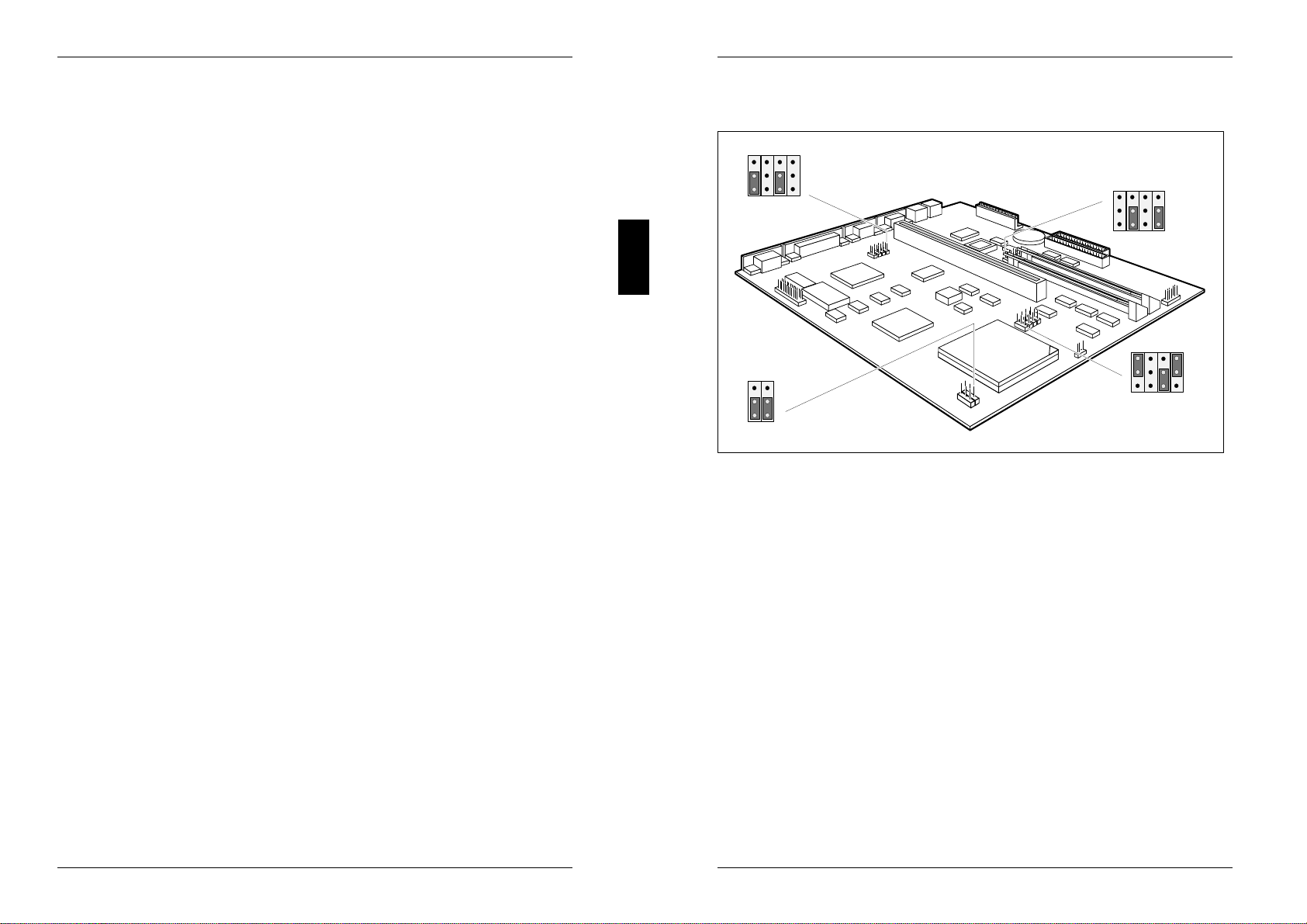
Settings
Jumper
FD_PRT
RTCINI
IRQ12
FLASH
33/25M
COLOUR
RES 1
DX/SX
BLOCK1
BLOCK2
BLOCK4
3
2
1
3
2
1
3
2
1
RES 2
IRQ9
RES 3
VGA
BLOCK3 3
2
1
WT
RS
BLOCK1 = Floppy disk drive write protection BLOCK3 = VGA interrupt IRQ9 and
and Mouse interrupt IRQ12 monitor controller
BLOCK2 = external clock rate, primary BLOCK4 = First level cache
monitor controller and
processor type
Write protection for floppy disk drive
The jumper BLOCK1-FD_PRT is used to define whether floppy disks can be
written or deleted in the floppy disk drive. To write and delete floppy disks, the field
Diskette Write must be set to ENABLED in the System Security Options setup menu.
Read, write and delete floppy disks = jumper BLOCK1-FD_PRT is set to 1-2
Read only floppy disks = jumper BLOCK1-FD_PRT is set to 2-3
Default setting:
Jumper BLOCK1-FD_PRT is set to 1-2 = read, write and delete floppy disks
enabled
20 A26361-D824-Z120-5-7619

Settings
Mouse interrupt IRQ12
With the jumper BLOCK1-IRQ12 you can set the interrupt IRQ12.
IRQ12 used by mouse = jumper BLOCK1-IRQ12 set to 1-2
IRQ12 not used = jumper BLOCK1-IRQ12 set to 2-3
Default setting:
Jumper BLOCK1-IRQ12 set to 1-2 = IRQ12 used by mouse
VGA interrupt IRQ9
With the jumper BLOCK3-IRQ9 you can set the interrupt IRQ9.
IRQ9 not used = jumper BLOCK3-IRQ9 set to 1-2
IRQ9 used by VGA controller = jumper BLOCK3-IRQ9 set to 2-3
Default setting:
Jumper BLOCK3-IRQ9 set to 1-2 = IRQ9 not used
Processor settings
When you upgrade the processor, you must check and set the jumpers
BLOCK2-33/25M and BLOCK2-DX/SX.
External clock rate
With the jumper BLOCK2-33/25M you can define the external clock rate of the
processor (33 MHz or 25 MHz).
External clock rate 25 MHz = Jumper BLOCK2-33/25M set to 1-2
External clock rate 33 MHz = Jumper BLOCK2-33/25M set to 2-3
Default setting:
Depending on the built-in processor
A26361-D824-Z120-5-7619 21
Settings
Processor type
With the jumper BLOCK2-DX/SX you can define the processor type.
SX processor = Jumper BLOCK2-DX/SX set to 1-2
All other processor types (including SX2) = Jumper BLOCK2-DX/SX set to 2-3
Default setting:
Depending on the built-in processor
First level cache
The setting of the jumpers BLOCK4-WT and BLOCK4-RS depends on the first
level cache.
If the system board is fitted with a processor with a write-back cache (e.g. Pentium
OverDrive, i486DX2A), the jumpers must be set to 2-3. If it is fitted with a processor
with a write-through cache (e.g, DX, DX2, etc.) the jumpers must be set to 1-2.
Write-through = jumper BLOCK4-WT and BLOCK4-RS are set to 1-2
Write-back = jumper BLOCK4-WT and BLOCK4-RS are set to 2-3
Default setting:
depends on the type of processor installed
Monitor controller settings
Primary monitor controller
With the jumper BLOCK2-COLOUR you can set the primary monitor controller.
Color monitor controller = Jumper BLOCK2-COLOUR set to 1-2
Monochrome monitor controller = Jumper BLOCK2-COLOUR set to 2-3
Default setting:
jumper BLOCK2-COLOUR set to 1-2 = Color monitor controller
Monitor controller on the system board
With the jumper BLOCK3-VGA you can enable or disable the monitor controller on
the system board.
Monitor controller enabled = Jumper BLOCK3-VGA set to 1-2
Monitor controller disabled = Jumper BLOCK3-VGA set to 2-3
Default setting:
Jumper BLOCK3-VGA set to 1-2 = Monitor controller enabled
22 A26361-D824-Z120-5-7619

Add-on modules
3
4
5
1
2
6
7
1 = Location lithium battery 5 = Socket for processor
2 = Location bank 1 for main memory 6 = Socket for video memory
3 = Location bank 0 for main memory 7 = Connector for external monitor controller
4 = Connector for external loudspeaker (VESA VGA pass through)
Upgrading main memory
Two locations (Bank 0 and Bank 1) are available on the system board for
connecting memory modules.
The board supports a maximum of 32 Mbytes. You may use memory modules of 4,
8, 16 or 32 Mbytes. For the memory configuration we recommend to use memory
modules of the same capacity.
If you want to install or remove memory modules, you must remove the drive
carrier (see Technical Manual of the PC).
!You may only use fast memory modules (access time = 70ns or less).
A26361-D824-Z120-5-7619 23
Add-on modules
Installing memory modules
If you want to install several memory modules, plug the first memory module into
the bank 0.
1
2
Insert the memory module at angle into the appropriate location (1).
Ensure that the key notch and the two holes are correctly aligned with the
retaining pins.
Tilt the module down until it snaps into place (2).
Removing a memory module
1
1
3
2
Carefully push the retaining clips at each end of the module outwards (1).
Tilt the module upwards (2) and pull it at an angle out of the location (3).
24 A26361-D824-Z120-5-7619

Add-on modules
Upgrading the processor
12
Remove the old processor from the socket.
Insert the new processor in the socket so that the mark on the upper side of the
processor (2) matches the mark on the socket (1).
The mark on the processor may be covered by a heat sink. In this case let
yourself be guided by the marking in the rows of pins on the underside of the
processor.
Set the jumpers BLOCK2-33/25M, BLOCK2-DX/SX and BLOCK4 according to
the inserted processor.
Upgrading the video memory
If your PC is supplied with a video memory configuration of 512 Kbytes, you may
enlarge the video memory up to 1 Mbyte.
!Information on which DRAM components you can use is available from your
sales office or the customer service.
Note the location of the DRAM chip when you plug in DRAM chip!
A26361-D824-Z120-5-7619 25
Add-on modules
12
Insert the DRAM component in such a way that the mark on the upper side of
the DRAM component (2) matches the position of the mark on the socket (1).
Replacing the lithium battery
!Incorrect replacement of the lithium battery may lead to a risk of explosion.
The lithium battery must be replaced with an identical battery or a battery
type recommended by the manufacturer (CR2032).
Do not throw lithium batteries into the trashcan. Your vendor or dealer or
their authorized representatives will take used batteries back free of charge
so that they can be recycled or disposed of in the proper manner.
Make sure that you insert the battery the right way round. The plus pole
must be on the top.
1
23
+
++
+
Lift the contact (1) a few millimeters and remove the battery from its socket (2).
Insert a new lithium battery of the same type in the socket (3).
26 A26361-D824-Z120-5-7619

Interface pinouts and interrupts
Connector for power supply
1
12
Pin Meaning
1 Power good
2 +5 V
3 +12 V
4 -12 V
5-8 0 V
9 -5 V
10-12 + 5 V
Connector for LED indicators
17
6
Pin Signal name
1 System unit ON
2 not used
3 coded
4 not used
5 Reset switch
6 +5 V
7 0 V
8 0 V
9 coded
10 0 V
11 0 V
12 Hard disk drive LED
A26361-D824-Z120-5-7619 27
Interface pinouts and interrupts
Connector for VESA VGA pass-through
26
12
Pin Meaning Pin Meaning
1 0 V 14 Data 6
2 Data 0 15 0 V
3 0 V 16 Data 7
4 Data 1 17 0 V
5 0 V 18 Clock
6 Data 2 19 0 V
7 not used 20 Blanking
8 Data 3 21 0 V
9 not used 22 Horizontal Sync.
10 Data 4 23 not used
11 not used 24 Vertical Sync.
12 Data 5 25 coded
13 not used 26 0 V
28 A26361-D824-Z120-5-7619

Interface pinouts and interrupts
Connector for external loudspeaker
1
4
Pin Meaning
1 loudspeaker
2 coded
3 0 V
4 +5 V
Connector for monitor
1
5
6
10
11
15
Pin Meaning Pin Meaning
1 Red 9 coded (no pin)
2 Green 10 Sync. ground
3 Blue 11 Monitor ID bit 0
4 Display ID bit 2 12 Monitor ID bit 1
5 Ground 13 Horizontal
6 Red ground synchronization
7 Green ground 14 Vertical synchronization
8 Blue ground 15 Monitor ID bit 3
A26361-D824-Z120-5-7619 29
Interface pinouts and interrupts
Parallel interface
1
13
25 14
Pin Signal name Description
1 STROBE Data message
2-9 Data Lines 0-7 Data lines 0-7
10 ACKNOWLEDGE Data acknowledgement
11 BUSY Not ready to receive
12 PE End of paper
13 SELECT Device selection
14 AUTO Automatic new line
15 ERROR Device error
16 INIT Reset/initialize
17 SELECT IN Printer selection
18-25 GROUND Ground
PS/2 mouse port
1
4
2
3
5
6
Pin Signal
1 Data
2 not used
3 0 V
4 +5 V
5 Clock
6 not used
30 A26361-D824-Z120-5-7619

Interface pinouts and interrupts
PS/2 keyboard port
1
4
2
3
5
6
Pin Signal
1 Data
2 not used
3 0 V
4 +5 V
5 Clock
6 not used
Serial interface
15
69
Pin Signal Meaning
1 DCD Data Carrier Detect
2 RxD Receive Data
3 TxD Transmit Data
4 DTR Data Terminal Ready
5 Signal Ground Ground
6 DSR Data Set Ready
7 RTS Request to Send
8 CTS Clear to Send
9 Ri Ring Indicator
A26361-D824-Z120-5-7619 31
Interface pinouts and interrupts
Interrupt Request Levels and DMA channels
Interrupt Request Levels and DMA channels are listed below.
Interrupt Request Levels
IRQ0 = timer 0
IRQ1 = keyboard
IRQ2 = free or IRQ9
IRQ3 = serial interface 2 (COM2/COM4)
IRQ4 = serial interface 1 (COM1/COM3)
IRQ5 = free
IRQ6 = floppy disk controller
IRQ7 = parallel interface (LPT1/LPT3)
IRQ8 = real-time clock interrupt
IRQ9 = VGA controller or free
IRQ10 = free
IRQ11 = free
IRQ12 = mouse
IRQ13 = math coprocessor
IRQ14 = IDE hard disk controller
IRQ15 = free
DMA channels
DMA0 = free
DMA1 = free - normally used by LAN
DMA2 = floppy disk controller
DMA3 = IDE
DMA4 = DMA channel cascading
DMA5 = free
DMA6 = free
DMA7 = free
32 A26361-D824-Z120-5-7619
This manual suits for next models
1
Table of contents
Other Siemens Nixdorf Motherboard manuals

Siemens Nixdorf
Siemens Nixdorf D1111 User manual

Siemens Nixdorf
Siemens Nixdorf D1025 User manual

Siemens Nixdorf
Siemens Nixdorf Fujitsu D1160 User manual

Siemens Nixdorf
Siemens Nixdorf D1042 User manual

Siemens Nixdorf
Siemens Nixdorf D756 User manual

Siemens Nixdorf
Siemens Nixdorf D858 User manual

Siemens Nixdorf
Siemens Nixdorf D818 User manual

Siemens Nixdorf
Siemens Nixdorf D970 User manual

Siemens Nixdorf
Siemens Nixdorf D802-C User manual

Siemens Nixdorf
Siemens Nixdorf Fujitsu D1115 User manual


