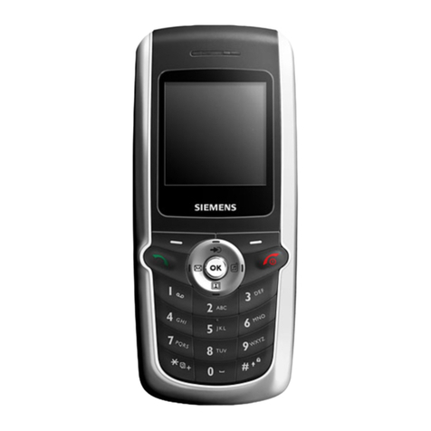
Siemens AX75 User manual

Local Service Organization Service Manual
BE INSPIRED
A
A
AX
X
X7
7
75
5
5
Release Date Department Notes to changes
V1.0 06.06.2005
COM D CCQ SLI APAC New Documents
Our innovation shapes the future

AX75 Level 2 Service Manual
Copyright © Siemens Pte Ltd.
All Rights Reserved May 2005
COM D CCQ SLI APAC Page 2 of 34 Internal Use Only
Table of Contents
1 GPRS (GENERAL PACKET RADIO SERVICE)…………………..…….3
2 KEY FEATURES……………………………………………………………………….4
3 COMPARISON WITH PREVIOUS PRODUCT...……………………………………6
4 ACCESSORIES……………………………………………………………………......7
5 UNIT DESCRIPTION AX75......................................................................................9
6 DISASSEMBLY OF AX75…………………………………………………………...11
7 REASSEMBLY OF AX75….………………………………………………………...16
8 MOBILE SOFTWARE PROGRAMMING…………………………………………..17
9 SIEMENS SERVICE EQUIPMENT USER MANUAL……………………………..20
10 JPICS INTERNET.……………………………………………………………………21
11 INTERNATIONAL MOBILE EQUIPMENT IDENTITY, IMEI…….………………..27
12 GENERAL TESTING INFORMATION……………………………….……………..28
Annex 1……………………………………………………………………………….……….33
Annex 2…………………………………………………………………………….………….34

AX75 Level 2 Service Manual
Copyright © Siemens Pte Ltd.
All Rights Reserved May 2005
COM D CCQ SLI APAC Page 3 of 34 Internal Use Only
1 GPRS (General Packet Radio Service)
GPRS is a new non-voice value added services that allows information to be sent
and received across a GSM mobile telephone network. It supplements today’s Circuit
Switched Data (CSD) and Short Message Services (SMS). GPRS involves overlaying
a packet based air interface on the existing circuit switched GSM network. This gives
the option to use a packet-based data service. The information is split into separated
but related “packets” before being transmitted and reassembled at the receiving end.
Theoretically, maximum speeds of up to 171.2 kilobits per second (kbps) are
achievable with GPRS using all eight timeslots at the same time. This is about 3
times as fast as the data transmission speed possible over today’s fixed
telecommunications networks and 10 times as fast as current Circuit Switched Data
services on GSM networks.
Example: Cell with 1 Frequency channel:
1 physical channel for signaling, 4 physical channels for Circuit switched and 3 physical
channels for Packet switched.

AX75 Level 2 Service Manual
Copyright © Siemens Pte Ltd.
All Rights Reserved May 2005
COM D CCQ SLI APAC Page 4 of 34 Internal Use Only
2 Key Features
Bands • Triple Band E-GSM 900 / GSM 1800 / GSM 1900
• EGSM Phase 2 / phase 2+
• GPRS Multi Class 8
Battery • Li-Ion Battery Pack
• Nominal Voltage : 3.7V
• Nominal Capacity : 600 mAh
• GSM Capacity: 580 mAh
• Power Input: 2.0 A (0.6 ms) / 0.25 A (0.4 ms)
• Cut-off Threshold 3.2 V
Stand-by Time • up to 220 h (standard battery)
Talk Time • up to 300 min (standard battery)
SIM Card
• Small (”Plug In”) 3V SIM card (Phase II)
• To insert the SIM card, the battery pack must be
removed.
GSM Antenna • Integrated triple band antenna for EMEA/APAC.
Dimensions • 101 x 44 x 20 mm (L x W x H)
Weight • Approx. 80 g
Charging time • < 2 h for 100%
Receiver Sensitivity • GSM 900: -102dBm (Specification, static & with fading)
• GSM 1800/1900: -102 dBm (Specification, static & with
fading)
Receiver sensitivity must comply with the corresponding GSM
recommendations in all operating conditions (temperature,
battery level, etc)
Transmitter Power • GSM 900: nominal 2W (Specification: Class 4 Mobile
phone)
• GSM 1800/1900: nominal 1W (Specification: Class 1
Mobile phone)
Transmitter output characteristics is according to GSM 11.10
specification implying all specified operating conditions
(temperature, battery level ...).
Transmitter set points will be specified for GSM and PCN when
typical values and statistical values become available.
Speech Codec
• Half Rate, Full Rate, Enhanced Full Rate and Adaptive
Multi Rate speech coders are available as standard.
Temperature
Range • -100C to +550C (Normal operation)
• -300C to +850C (Storage capability)

AX75 Level 2 Service Manual
Copyright © Siemens Pte Ltd.
All Rights Reserved May 2005
COM D CCQ SLI APAC Page 5 of 34 Internal Use Only
Display • Type: Full Graphic
• Resolution: 130 x 130 Pixel
• No. of colours: 65K
• Technology: C-STN
• Active area: 27.3mm x 27.3mm
• Pixel size: 0.21mm x 0.21mm. (1 Pixel consists of 3
sub-pixels in red, green and blue)
• Illumination: White (3 LEDs integrated)
• Frame Rate: 15 frames/sec
12-Block Keypad • IMF technology
• 12-key-block (0-9, #, *)
• two function keys (SEND, END)
• ON/OFF key combined with the END key; the symbol (I
inside O) is used as a symbol for ON/OFF.
• 4 way-navikey
• 2 soft-keys for different SW-enabled functions
• tactile finder on key “5“
• 6 amber LEDs for keypad
Acoustics
• Three-in-one-earpiece for handset, handsfree and ringing
tones
• Omnidirectional microphone
• Loud signal emitter (soundringer) (>100dB(A) SPL @5cm,
'Hongkong-Spec.') only for rectangular sound signals (NOT
POSSIBLE for Soundringer melodies)
• Polyphonic ringer tones 16 voices
• Different selectable volume levels for handsfree, handset
and ringer mode (for the amount see SW product
description)

AX75 Level 2 Service Manual
Copyright © Siemens Pte Ltd.
All Rights Reserved May 2005
COM D CCQ SLI APAC Page 6 of 34 Internal Use Only
3 Comparison with Previous Product
Feature A65 AX75
Supported Systems Triple Band
EGSM900/GSM1800/GSM190
(EMEA, APAC)
Triple Band
EGSM 900/GSM1800/
GSM1900 (EMEA, APAC)
GSM 850/GSM1800/
GSM1900 (LAM)
Stand-by Time Up to 250 h Up to 220 h
Talk Time Up to 5h Up to 5 h
Battery Technology
Battery Capacity Li-Ion Battery Pack
Nominal Cap.: 700 mAh Li-Ion Battery Pack
Nominal Cap.: 600 mAh
Weight 74.8 g Approx. 80 g
Volume 71.8 cm3Approx. 74.6 cm3
Length 100.7 mm 105.6 mm
Width 44.7 mm 46.75 mm
Thickness 19.3 mm 17.5 mm
SIM Plug-In 3V Plug-In 3V
Antenna Integrated Integrated
Antenna Performance
FBT EMEA/APAC
TRP freespace (avg)
29dBm @900MHz
26dBm @1800MHZ
26dBm @1900MHZ
TIS freespace (avg)
-102dBm
Head SAR < 0.8 W/kg
(1g)
29.4 dBm @ 900 MHz
26.4 dBm @ 1800 MHz
27.8 dBm @ 1900 MHz
-103 dBm @ 900 MHz
-104.5 dBm @ 1800 MHz
-103.7 dBm @ 1900 MHz
SAR = 0.79 W/kg (1g)
AX70 EMEA/APAC
29dBm @ 900 MHz
26dBm @ 1800 MHz
26dBm @ 1900 MHz
-102dBm
SAR < 0.80 W/kg (1g)
Antenna Performance
FBT LAM version
28dBm @850MHz
26dBm @1800MHz
27.5Bm @1900MHz
TIS freespace (avg)
-102dBm
Head SAR < 0.8 W/kg
(1g)
AX7X LAM
28dBm @ 850 MHz
26dBm @ 1800 MHz
26dBm @ 1900 MHz
-102dBm
SAR < 0.80 W/kg (1g)
Half Rate Yes Yes
Enhanced Full Rate Yes Yes
AMR Yes Yes
Fax/Data No Yes
GPRS Yes (Class 8) Yes (Class 8)
Keypad Illumination Yes (amber) Yes (amber)
Display /
Display Illumination CSTN 4k colours (101x80 dots) Main: CSTN 64k colours
(130x130)
Camera No No
Connectivity Serial Serial, IRDA
Ringer volume level Min. 100 dB(A) @ 5cm
Typ. >103 dB(A) @ 5cm Min. 100dB(A) @ 5cm
(only for rectangular sound
signals)

AX75 Level 2 Service Manual
Copyright © Siemens Pte Ltd.
All Rights Reserved May 2005
COM D CCQ SLI APAC Page 7 of 34 Internal Use Only
4 Accessories
For AX75, the following accessories will be available.
Description Part number
Belt Case FCL-600 L36880-N7101-A120
Tour Case FCT-650 L36880-N5601-A149
Headset Purestyle HHS-610 L36880-N7101-A500
Headset HHS-510 L36880-N5601-A108
Headset Basic HHS-500 L36880-N5601-A107
Li-Ion Battery 750mAh EBA-660 L36880-N7101-A111
Travel Charger ETC-500 L36880-N5601-A104
Travel Charger ETC-510 L36880-N5601-A105
Car Charger Plus ECC-600 L36880-N7101-A109
Desk Top Stand EDC-500 TBC
Car Charger ECC-500 TBC
Car Kit Easy HKP-700 TBC
Car Kit Portable HKP-500 L36880-N5601-A109
Car Kit Easy Upgrade HKO-700 TBC
QuickPic Camera IQP-500 L36880-N5701-A109
Data Cable DCA-500 (RS232) L36880-N5601-A110
Data Cable USB DCA-510 L36880-N5601-A111
Note: Visit the Communication Market for updated accessories:
https://communication-market.siemens.de/

AX75 Level 2 Service Manual
Copyright © Siemens Pte Ltd.
All Rights Reserved May 2005
COM D CCQ SLI APAC Page 8 of 34 Internal Use Only
4.1 AX75 Interface to accessories
There are no specific mechanical interfaces to the car cradle. The car cradle is designed
to fit the existing design. The I/O-Connector (Lumberg-slim-connector) is in use. The
compatible interface is suitable to use the travel charger.
Slim Lumberg I/O Connector

AX75 Level 2 Service Manual
Copyright © Siemens Pte Ltd.
All Rights Reserved May 2005
COM D CCQ SLI APAC Page 9 of 34 Internal Use Only
5 Unit Description of AX75
The AX75 Pegasus is designed as a Mono Block with non-exchangeable housing. The
Upper case, lower case and battery cover are painted parts (1k; 2 colours). IMD Lens will
be mounted by Ultrasonic, Display, 130X130(modified from Hera, only mechanical
modification); semi-bridgeless keypad, 4-way Navi-Key, 12 keys block; IMD lens (1 pcs
only); IRDA window; No ID concept will be realized on Battery cover.

AX75 Level 2 Service Manual
Copyright © Siemens Pte Ltd.
All Rights Reserved May 2005
COM D CCQ SLI APAC Page 10 of 34 Internal Use Only
5.1 Exploded View of AX75
Upper case shell
Keypa
Metal dome foil
Microphon
Earphone
Display
Main
Vibramoto
r
Lower mounting frame
Screw
Battery cove
r
Battery Li-ion

AX75 Level 2 Service Manual
Copyright © Siemens Pte Ltd.
All Rights Reserved May 2005
COM D CCQ SLI APAC Page 11 of 34 Internal Use Only
6 Disassembly of AX75
Note: ESD concept; the internal circuits will be more susceptible to ESD because of
the use of exchangeable housing. The construction of the internal block must be/is
designed, in the best possible way, to protect the circuit against sparks.
The keypad must be completely closed to prevent any occurrence of an ESD
disruptive discharge.
The SIM contacts may be open, thus reachable for ESD contact discharge. This
could lead to damage or destruction of the E-Gold pins.
It is a requirement for the service personnel to observe ESD protection rules while
performing servicing the AX75.
Step 1
Front view of the AX75
Step 2
Back View of the AX75
Step 3
Remove Battery cover.

AX75 Level 2 Service Manual
Copyright © Siemens Pte Ltd.
All Rights Reserved May 2005
COM D CCQ SLI APAC Page 12 of 34 Internal Use Only
Step 4
Remove Battery
Step 5
Remove SIM Card
Step 6
Remove the 4 screws (as indicated) with T5 Plus screw driver.

AX75 Level 2 Service Manual
Copyright © Siemens Pte Ltd.
All Rights Reserved May 2005
COM D CCQ SLI APAC Page 13 of 34 Internal Use Only
Step 7
Remove Vibramotor
Step 8
Remove Microphone
Step 9
Remove Main board.

AX75 Level 2 Service Manual
Copyright © Siemens Pte Ltd.
All Rights Reserved May 2005
COM D CCQ SLI APAC Page 14 of 34 Internal Use Only
Step 10
Remove Display module. Place foil over Display module for protection
Step 11
Remove Earphone
Step 12
Remove Keypad

AX75 Level 2 Service Manual
Copyright © Siemens Pte Ltd.
All Rights Reserved May 2005
COM D CCQ SLI APAC Page 15 of 34 Internal Use Only
Step 13
Fully disassembled AX75

AX75 Level 2 Service Manual
Copyright © Siemens Pte Ltd.
All Rights Reserved May 2005
COM D CCQ SLI APAC Page 16 of 34 Internal Use Only
7 Reassembly of AX75
For the reassembly of the AX75, reverse the disassembly procedures from Step 12 to
Step1. However there are some areas to be taken note of during reassembling of the
phone.
During the installation of the SIM card, make sure that the SIM card is inserted properly and
that the golden contact area is facing downwards. Insert the SIM card downwards to lock the
SIM card into position.
Installation of the SIM card
During the installation of the battery, make sure that the hinges are properly in place (See picture
below). Otherwise the battery will not be able to fit into the phone properly.
When placing the screws, set Torque to 17cNm.

AX75 Level 2 Service Manual
Copyright © Siemens Pte Ltd.
All Rights Reserved May 2005
COM D CCQ SLI APAC Page 17 of 34 Internal Use Only
8 Mobile Software Programming
The common mobile software available is divided into language groups. However, this
software does not contain the specific settings, such as ringing tones, greeting text, and
short dial list etc., required by the operator or service provider. Therefore, it is common to
have some menu item(s) differ in different variants or are not visible at all. These settings
are stored in different memory area of the mobile and will be activated depending on the
customer specific model or variant of the phone by a separate test step during the
production process.
Due to this separation of common mobile software and customer specific initialization, it
is possible to fulfil the demands of the market requiring customization and flexibility. As a
consequence the software programming process in the LSO is divided into two different
steps as followed:
- Software update to actual version and appropriate language group
- Programming of CUSTOMER SPECIFIC INITIALIZATION
Usage of GRT is mandatory!! For more detail check GRT User manual
Figure 1. AX75 Software Programming Setup

AX75 Level 2 Service Manual
Copyright © Siemens Pte Ltd.
All Rights Reserved May 2005
COM D CCQ SLI APAC Page 18 of 34 Internal Use Only
8.1 Mobile Software Updating
The software of the 75 series mobiles, is loaded from a PC directly. Hardware
interconnection between the mobile and the PC is shown in Figure 1. Because of the new
type of external connector used since 55 series (Slim-Lumberg type) an additional
adaptor cable between mobile and boot adaptor is required. Table 1 listed all the
hardware requirements
If you use the battery dummy, make sure that the power supply voltage is correctly
adjusted.
Description Part No.
Bootadapter 2000 incl. AC-Adapter, serial
cable and mobile connection cable L36880-N9241-A200
IBM Compatible PC – Pentium -
Adapter cable – Slim Lumberg to Old F30032-P226-A1
TABLE 1. EQUIPMENT LIST FOR SOFTWARE PROGRAMMING

AX75 Level 2 Service Manual
Copyright © Siemens Pte Ltd.
All Rights Reserved May 2005
COM D CCQ SLI APAC Page 19 of 34 Internal Use Only
8.2 Flow Chart for Software Upgrading
NO
YES
NO
YES
NO
YES
NO
YES
Plug in the Boot
Adaptor to the PC
and Mobile
Connect the AC
adaptor to the
Boot Adaptor
Power up Boot
Adaptor & check
LED.
OK?
Check AC Adaptor
OK?
Faulty AC Adaptor
Faulty Boot
Adaptor
Start the SWUP
program
Select & Execute
the "Mobile S/W"
ERROR?
Check
H/W setup = S/W
OK?
Correct Settings
S/W upgrading in
progress
ERROR?
TEST Mobile
Take note of error
and repeat
process
Feedback Error to
Tech. Supp. Dep
END
FLOW CHART FOR S/W PROGRAMMING PROCESS

AX75 Level 2 Service Manual
Copyright © Siemens Pte Ltd.
All Rights Reserved May 2005
COM D CCQ SLI APAC Page 20 of 34 Internal Use Only
9 Siemens Service Equipment User Manual
Introduction
Every LSO repairing Siemens handset must ensure that the quality standards are
observed. Siemens has developed an automatic testing system that will perform all
necessary measurements. This testing system is known as:
Siemens Mobile Service Equipment
All mobile Phones have to be tested with the GRT-Software.
The Service Partner is responsible to ensure that all required hardware is
available.
For additional Software and Hardware options as well as the supported GRT
equipment, please check the GRT User manual
Other manuals for AX75
3
Table of contents
Other Siemens Cell Phone manuals

Siemens
Siemens Gigaset SL75 WLAN User manual

Siemens
Siemens Gigaset SL56 User manual

Siemens
Siemens CF62 User manual

Siemens
Siemens C65 User manual

Siemens
Siemens RF182C User manual

Siemens
Siemens A55 Operator's manual

Siemens
Siemens S55 User manual

Siemens
Siemens SXG75 User manual

Siemens
Siemens A53 User manual

Siemens
Siemens SX1 Operator's manual

Siemens
Siemens AX76 User manual

Siemens
Siemens Be inspired M55 User manual

Siemens
Siemens M65 User manual

Siemens
Siemens S55 User manual

Siemens
Siemens CL75 Setup guide

Siemens
Siemens XELIBRI 2 User manual

Siemens
Siemens M46 User manual

Siemens
Siemens mobile phone User manual

Siemens
Siemens SL45i User manual

Siemens
Siemens CF75 Setup guide