Private Communication Systems
Mobile Phones
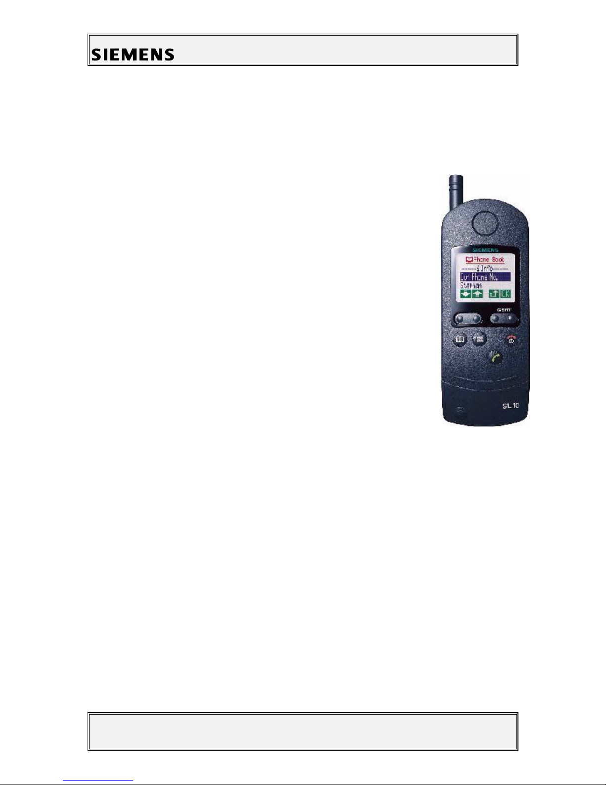
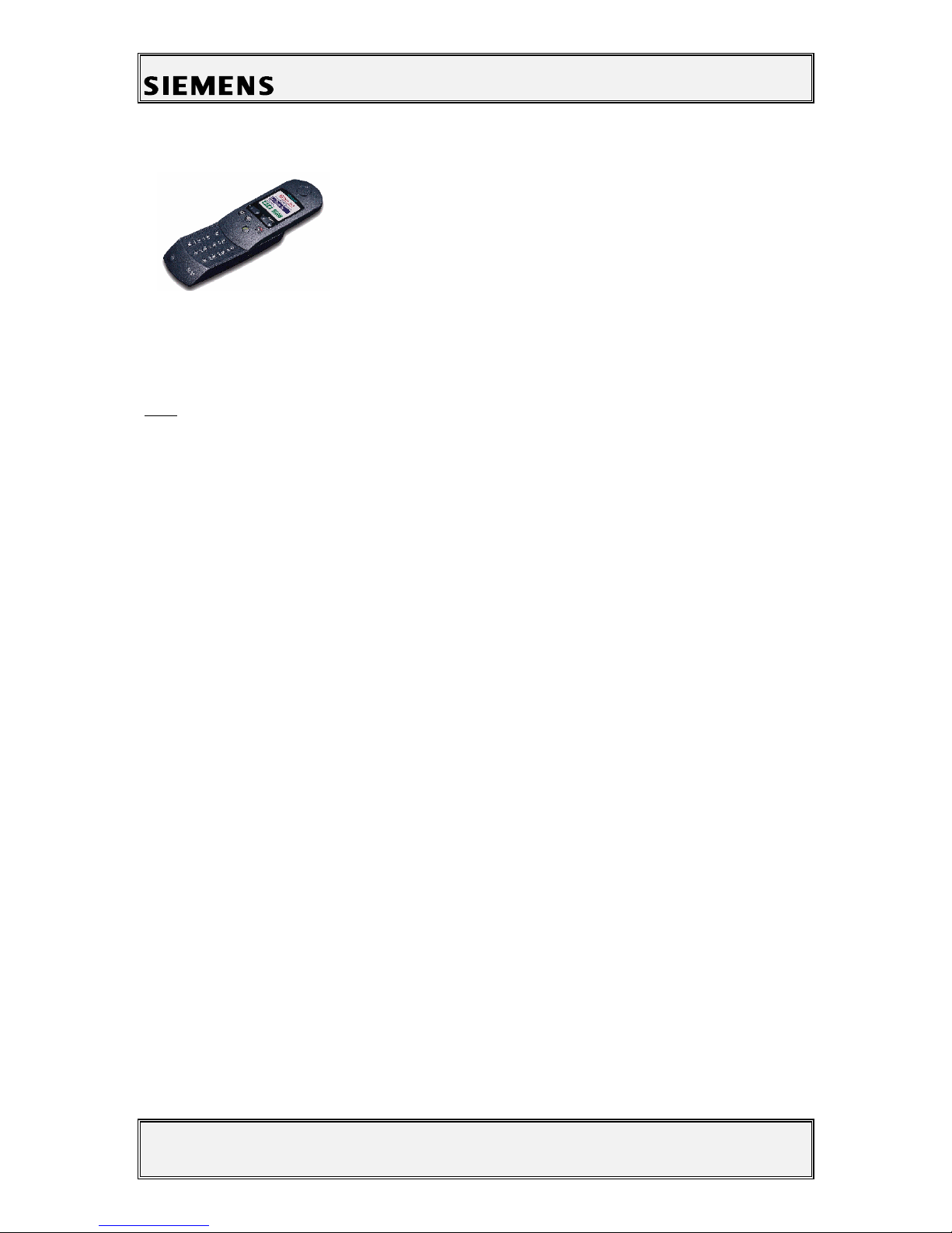
Service Manual SL10 V1.1 PN MP ST
R. Fleuren
Sm_sl10_lvl2_v11.doc Page 2 of 22 05/98
1 Table of Contents
1 TABLE OF CONTENTS....................................................................................................................................2
2 TECHNICAL DATA ..........................................................................................................................................3
3 GENE AL INFO MATION ............................................................................................................................4
4 MECHANICAL CONCEPT..............................................................................................................................4
4.1 MECHANICAL DRAWING OF THE SL10.................................................................................................................5
4.2 DISASSEMBLING THE SL10 .................................................................................................................................6
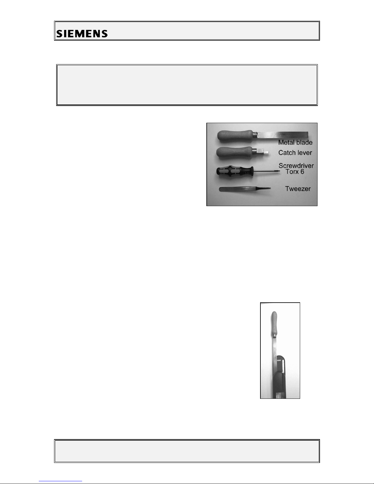
4.2.1 Necessary ools .......................................................................................................................................6
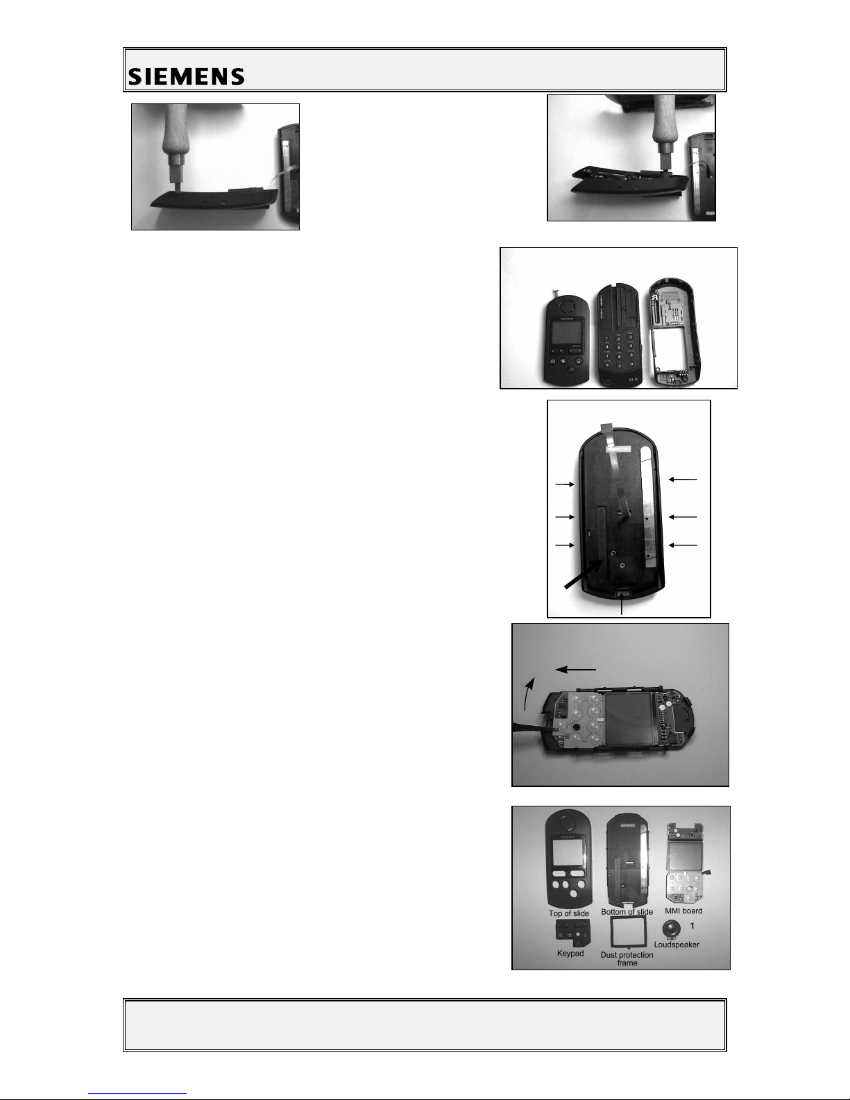
4.2.2 Disassembling he Mobile.......................................................................................................................6
4.2.3 Disassembling he Slide ..........................................................................................................................8
4.2.4 Disassembling he Top Par of he Base .................................................................................................9
4.2.5 Disassembling he Bo om Par of he Base..........................................................................................10
4.3 ASSEMBLING THE SL10 ....................................................................................................................................10
4.3.1 Assembling he Bo om Par of he Base ..............................................................................................10
4.3.2 Assembling he Top Par of he Base....................................................................................................11
4.3.3 Assembling he Slide ............................................................................................................................11
4.3.4 Assembling he Mobile .........................................................................................................................12
4.4 HANDSET DATECODES ......................................................................................................................................13
5 HA DWA E CONCEPT................................................................................................................................14
5.1 BLOCK DIAGRAM..............................................................................................................................................14
5.2 HARDWARE DESCRIPTION.................................................................................................................................15
5.3 POWER SUPPLY CONCEPT .................................................................................................................................16
5.4 LIMITS OF VOLTAGE AND CURRENT..................................................................................................................17
6 BATTE Y .........................................................................................................................................................18
6.1 SPECIFICATION..................................................................................................................................................18
6.2 SHORT CIRCUIT PROTECTION............................................................................................................................18
6.3 DEEP DISCHARGE..............................................................................................................................................18
6.4 BATTERY DATECODES ......................................................................................................................................19
7 SOFTWA E P OG AMMING ....................................................................................................................20
7.1 DESCRIPTION OF SOFTWARE BOOTING...............................................................................................................20
7.2 LANGUAGE GROUPS..........................................................................................................................................21
8 UNBLOCKING.................................................................................................................................................21
8.1 SIEMENS HOTLINE.............................................................................................................................................21
8.2 INTERNET SOLUTION .........................................................................................................................................22