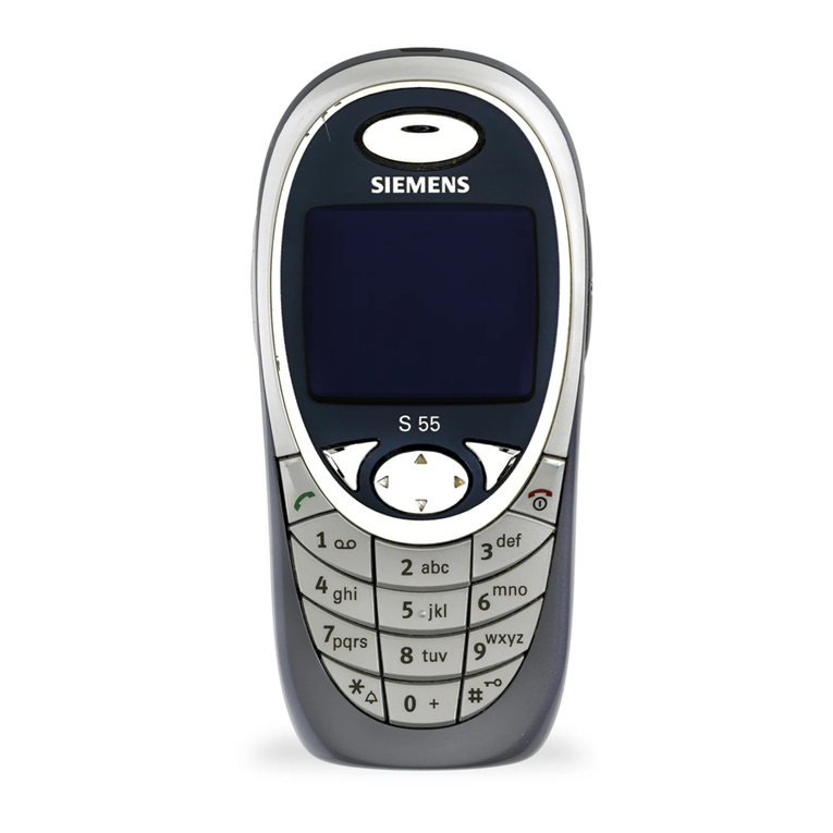
Siemens ST55 User manual

Local Service Organization Service Manual
BE INSPIRED
S
S
ST
T
T5
5
55
5
5
SIEMENS COMMUNICATIONS UNLIMITED
Version Date Department Notes to change
V1.00 01.08.2003 ICM MP CCQ SLI RHQ First release
Our innovation shapes the future

SIEMENS PTE LTD
ST55 Level 2 Service Manual
Copyright © Siemens Pte Ltd. Siemens Technical Support Centre
All Rights Reserved
ICM MP CCQ SLI RHQ 1 of 25 Internal Use Only
Table of Contents
1GPRS (GERENAL PACKET RADIO SERVICE)....................................................2
2K-JAVA APPLICATION...........................................................................................3
3KEY FEATURES………………………………………………………………………4
4ACCESSORIES ………………………………..……………………….……………..6
5UNIT DESCRIPTION ST55 ……...…...………………………………………………7
5.1 Exploded View of ST55 …….…………………………………………………….………..........8
6DISASSEMBLY OF ST55.....…………………………………………………………9
7REASSEMBLY OF SL55…………………………………………………………….12
8MOBILE SOFTWARE PROGRAMMING…………………………………………..14
8.1 Customer Mode (*#369#)………………………………………………………………….…...16
8.2 SW Version Definitions…….………………………………………….…………………….….16
9SIEMENS SERVICE EQUIPMENT USER MANUAL……………………………..17
10 INTERNATIONAL MOBILE EQUIPMENT IDENTITY, IMEI..…………………….18
11 GENERAL TESTING INFORMATION………………………….…………………..19
Annex 1………………………………………………………………………………..24
Annex 2………………………………………………………………………………..25

SIEMENS PTE LTD
ST55 Level 2 Service Manual
Copyright © Siemens Pte Ltd. Siemens Technical Support Centre
All Rights Reserved
ICM MP CCQ SLI RHQ 2 of 25 Internal Use Only
1GPRS (GENERAL PACKET RADIO SERVICE)
GPRS is a new non-voice value added services that allows information to be sent and received
across a GSM mobile telephone network. It supplements today’s Circuit Switched Data (CSD)
and Short Message Services (SMS). GPRS involves overlaying a packet based air interface on
the existing circuit switched GSM network. This gives the option to use a packet-based data
service. The information is split into separated but related “packets” before being transmitted and
reassembled at the receiving end. Theoretically, maximum speeds of up to 171.2 kilobits per
second (kbps) are achievable with GPRS using all eight timeslots at the same time. This is about
3times as fast as the data transmission speed possible over today’s fixed telecommunications
networks and 10 times as fast as current Circuit Switched Data services on GSM networks.
Figure1. Example of GPRS data transmission
Example:Cell with 1 Frequency channel:
1physical channel for signaling, 4 physical channels for Circuit switched and 3 physical channels
for Packet switched.

SIEMENS PTE LTD
ST55 Level 2 Service Manual
Copyright © Siemens Pte Ltd. Siemens Technical Support Centre
All Rights Reserved
ICM MP CCQ SLI RHQ 3 of 25 Internal Use Only
2K-JAVA APPLICATION
Java-based
game system
Java Application
Manager (JAM)
Application launcher and download
manager.
Supports HTTP-based OTA download of
applications over GPRS and CSD.
yes
RAM for Java
applications
Available RAM for Java applications (ie.
program code and data) during application
runtime:
Minimum: 100 Kbyte (Has to be taken as
working assumption for application
development.)
Goal: 145 Kbyte as SL45i (not committed)
yes
MIDP 1.0, CLDC 1.0 As SL45i, including performance
optimizations from SL45i-Infusio.
yes
'OEM extensions' Proprietary API extensions as SL45i.
Including 'Siemens Game API'
yes
HTTP API over GPRS SL45i: only over CSD yes

SIEMENS PTE LTD
ST55 Level 2 Service Manual
Copyright © Siemens Pte Ltd. Siemens Technical Support Centre
All Rights Reserved
ICM MP CCQ SLI RHQ 4 of 25 Internal Use Only
3Key Features
Frequency Bands •EGSM 900/GSM 1800/GSM 1900
Power •EGSM 900 : Power Class 4
•GSM 1800 : Power Class 1
•GSM 1900 : Power Class 1
Battery •Li-ion Battery Pack
•Nominal Voltage : 3.7V
•Nominal Capacity : 780mAh
Stand-by Time •Min 140 hrs (actual time depends on the network)
Talk Time •Best case : min 3.8 hours (DTX off, GSM 900, PL19)
•Best case : min 4.5 hours (DTX on 40% GSM 900,Pl19)
(Actual time depends on the network)
Charging Max charge time for empty battery (0-5% capacity) is 2.5 hrs for
standard charger and via battery charging station.
SIM Card •Plug In card 3V
•SIM application Tool Kit
Class II and III Send USSD command
Message SMS, EMS, MMS Support
Display •Backlight LED – LCD : White
Keypad: Blue
•LCD: 1.89” TFD module
120 x 160 pixel
16 bit (65536) colours
Camera Sensor •Focus Range: 50 cm ~
•Preview Mode: SUBQCIF 128 x 98

SIEMENS PTE LTD
ST55 Level 2 Service Manual
Copyright © Siemens Pte Ltd. Siemens Technical Support Centre
All Rights Reserved
ICM MP CCQ SLI RHQ 5 of 25 Internal Use Only
•Still pictures, tree qualities: High, Normal, Low
•Resolution – VGA (640 x 480), QVGA (320 x 240), QQVGA (160 x
120)
Physical Details •Dimension: 98.5 mm (L) x 48.86 mm (W) x 21.6 mm (H)
•Volume: ~ 75 cc
•Weight: ~ 87 g
Keypad •5-Way joystick
•2function keys (Send, Power / End)
•2multifunctional softkeys
•12 numeric keys (10 numeric,*, #)
Temperature
Range
•-10 oCto +55 oCfor normal operating
•-40 oCto +85 oCfor storage
Audio •Ringer: On / Off / Beep
•Melody: 20 embedded + 10 download + 3 compose
•Melody Type: YAMAHA SMAF MA3
•Key Tones: Click / Tone / Silent
•Info Tones: On/ Off / Extended
•Speaker Volume: Adjustable in 4 levels during call via volume key
Setting •User Profiles: Normal / Quiet / Noisy / Headset / Aeroplane mode / 2
Empty
•Group : Friends / Colleague / Family / Biz Partner / VIP
•Wallpaper: 3 default + 2 customized + OFF
•Answer Mode: Any key / Key Tones / Flap
•Security: Codes / Only > FDN > (Operator support) / This SIM only
Speech Codec •AMR, FR, EFR, HR
Interface •Bluetooth, USB, R232, IrDa, SyncML

SIEMENS PTE LTD
ST55 Level 2 Service Manual
Copyright © Siemens Pte Ltd. Siemens Technical Support Centre
All Rights Reserved
ICM MP CCQ SLI RHQ 6 of 25 Internal Use Only
4Accessories
For the ST55, the following accessories will be available.
Battery, Li-Ion (3.7V, 750mAh) Standard Charger
Download Cable

SIEMENS PTE LTD
ST55 Level 2 Service Manual
Copyright © Siemens Pte Ltd. Siemens Technical Support Centre
All Rights Reserved
ICM MP CCQ SLI RHQ 7 of 25 Internal Use Only
5Unit Description ST55
The mechanical concept of the ST55 as a bar phone type is much similar with other Siemens
series mobile phones.
ST55 can be divided into three main physical blocks, the top cover, middle frame and base cover.
The top cover is composed of internal and external LCD protected by LCD base and lens with
shielding effect. The LCD Lens will joint receiver and top cover.
For the main function assy., there are 2 screws located on the base and 2 on the M/B.
Screwdriver (T5) and tweezers will be used as main tools to perform mechanical repair.
Inside, the middle frame consist a M/B, which carries control and RF section of the mobile, and a
key PCB and microphone directly insert into plug-in connectors to show function. The display
module and vibrator are connected to the board by the board to board connector which is
inserted into a plug-in connector. In case they are defective electrically or mechanically it can be
exchanged very quickly. Camera module and antenna is attached on antenna frame which is
inserted on middle frame. The I/O connector for software upgrading and charging is located on
the bottom of middle frame.
The connector for external RF cable is located at the base cover of the mobile. Battery is
attached on the base cover and fix position with battery knob.
Notice: The ST55 is a dual-band mobile operating on GSM900 and GSM1800.

SIEMENS PTE LTD
ST55 Level 2 Service Manual
Copyright © Siemens Pte Ltd. Siemens Technical Support Centre
All Rights Reserved
ICM MP CCQ SLI RHQ 8 of 25 Internal Use Only
5.1 Exploded View of ST55

SIEMENS PTE LTD
ST55 Level 2 Service Manual
Copyright © Siemens Pte Ltd. Siemens Technical Support Centre
All Rights Reserved
ICM MP CCQ SLI RHQ 9 of 25 Internal Use Only
6Disassembly of ST55
Note: ESD concept; the internal circuits will be more susceptible to ESD because of the use of exchangeable
housing. The construction of the internal block must be/is designed, in the best possible way, to protect the circuit
against sparks.
Attention: Do not touch the screen of the display module when the upper case is removed! The module is damaged
after finger contact! Use a protection foil during disassembly and do not forget to remove this foil during reassembly.
The keypad must be completely closed to prevent any occurrence of an ESD disruptive discharge.
The SIM contacts may be open, thus reachable for ESD contact discharge. This could lead to damage or destruction of
the IC pins.
It is a requirement for the service personnel to observe ESD protection rules while performing servicing the ST55.
For assembly a torque T5 screw driver adjusted to 7Ncm is required.
Step 1
Remove BATTERY, CARKIT RUBBER and 2 SCREWS
(M1.6*6.5) located on BASE CASE ASSY.
Step 2
Detach the TOP CASE ASSY. by sliding the upper gap
from bottom to both sides.
Step 3
Remove the KEYSET from TOP CASE ASSY.
Step 4
Add a protect membrane on LCD. Remove 2 SCREWS
(M1.6*6.5) on top.

SIEMENS PTE LTD
ST55 Level 2 Service Manual
Copyright © Siemens Pte Ltd. Siemens Technical Support Centre
All Rights Reserved
ICM MP CCQ SLI RHQ 10 of 25 Internal Use Only
Step 5
Detach the BASE CASE ASSY. by sliding the lower gap
from bottom to both sides.
Step 6
Pull out CAREMA FPC carefully and detach the FRAME
CASE.
Step 7
Pull out LCD FPC carefully.
Step 8
Gently push apart the two clips of the metal snap to
release LCD MODULE from M/B.
Step 9
Remove JOYSTICK COVER and KEY SHIELD
Step 10
Lift the LCD CONNECTOR holder vertically and remove
the KEYPAD FPC from upper left corner carefully.
Step 11
Remove the MICROPHONE.
Step 12
Remove the SHIELD_BASE
1
2

SIEMENS PTE LTD
ST55 Level 2 Service Manual
Copyright © Siemens Pte Ltd. Siemens Technical Support Centre
All Rights Reserved
ICM MP CCQ SLI RHQ 11 of 25 Internal Use Only
Step 13
Remove the ANTENNA Assy. from FRAME CASE
by pressing the clip.
Step 14
Remove the CAMERA from ANTENNA FRAME by
slightly lifting the clip and pushing it forward.
Step 15
Unlock the screw (M1.6*1.5) on BASE CASE
ASSY. and remove the Vibrator.
Step 16
Fully disassembled ST55

SIEMENS PTE LTD
ST55 Level 2 Service Manual
Copyright © Siemens Pte Ltd. Siemens Technical Support Centre
All Rights Reserved
ICM MP CCQ SLI RHQ 12 of 25 Internal Use Only
7Reassembly of ST55
Step 1
Put back Vibrator into BASE CASE and tighten the
SCREW (M1.6*1.5).
Step 2
Align the position and push CAMERA into the
ANTENNA ASSY
Step 3
Align the position and push ANTENNA ASSY back to
FRAME CASE
Step 4
Assemble KEYPAD FPC, LCD Module
Step 5
Assemble SHIELD_KEY and MICROPHONE. The
SHIELD_KEY should hook on to the PCB properly at
the bottom.
Step 6
Place KEY JOYSTICK, the 2 bulges should be
positioned horizontally.

SIEMENS PTE LTD
ST55 Level 2 Service Manual
Copyright © Siemens Pte Ltd. Siemens Technical Support Centre
All Rights Reserved
ICM MP CCQ SLI RHQ 13 of 25 Internal Use Only
Step 7
Slide PCB into FRAME CASE from bottom and
connect CAMERA FPC
Step 8
Slide middle assy. into BASE CASE ASSY. from
bottom
Step 9
Reassemble the 2 screws (M1.6*6.5) located on the
PCB
Step 10
Reassemble KEYSET into TOP CASE ASSY
Step 11
Cover TOP CASE ASSY from top and press slightly to
close along both sides.
Step 12
Reassemble the 2 screws (M1.6*6.5) located on
BASE CASE ASSY. and place the CARKIT RUBBER.
1
2

SIEMENS PTE LTD
ST55 Level 2 Service Manual
Copyright © Siemens Pte Ltd. Siemens Technical Support Centre
All Rights Reserved
ICM MP CCQ SLI RHQ 14 of 25 Internal Use Only
8Mobile Software Programming
STL55 Software Programming Setup
The software of ST55 is loaded from a PC directly. All hardware interconnections are shown
above. Please make sure the capacity of battery is sufficient and the D/L cable connects well.
SW Download Process:
1. Install the download tool into PC just double click ”Setup.exe” in the folder and follow
instructions in process.
PC
Handset
Battery
RS232
D/L Cable

SIEMENS PTE LTD
ST55 Level 2 Service Manual
Copyright © Siemens Pte Ltd. Siemens Technical Support Centre
All Rights Reserved
ICM MP CCQ SLI RHQ 15 of 25 Internal Use Only
2. Execute the main program.
A) Click the wheel icon to load the related mbf file.
B) Press the power-on key until release message is shown. The downloading process will start.
3. After the downloading process is completed, remove the handset and connect to another.
Choose “Reset” to start download again.
A
B

SIEMENS PTE LTD
ST55 Level 2 Service Manual
Copyright © Siemens Pte Ltd. Siemens Technical Support Centre
All Rights Reserved
ICM MP CCQ SLI RHQ 16 of 25 Internal Use Only
8.1 Customer Mode (*#369#)
In ST55, the repair technicians can dial *#369# on handset under normal operating condition to
check or adjust the below functions. Please notice the items 4~6 are for production and RD’s
analysis, don’t change the default value or may cause mobile malfunction.
ContrastUp& Down to adjust; Select to exit.
BB Test: Up& Down to chose item; Select to enter.
Illumination: test if the backlight shows; OK to exit.
Speaker: test if the ring tone gives sound, OK to exit.
Vibrator: test if the vibrator starts, OK to exit.
Keypads: press each key to eliminate the indicators on screen;
long press OK to exit.
RTC status: show if the RTC OK; OK to exit.
Acoustic: blow to MIC and listen from Speaker; OK to exit.
LCD Test: Up& Down to check White, Black, R, B, G, R/G/B colour display; Exit to exit.
Software version:check the current software version
Mapping version:check the current software version
Auto-answer:factory usage, working when insert test SIM card
Comport:factory usage, AT-DATA/GENIE for RD analysis only.
DTMF-on:On/Off, determine if DTMF function valid during calling.
Camera:capture the image from camera to test if camera is working.
8.2 SW Version Definitions
The format of SW name shown on handset as below
Software Mapping
(Date Code) n- (TTP Version)
(Project) (Customer) (RD Version)
(Function)
(Date Code) -(Project) (Customer)-
(Region)(Structure Version)(Value Version)
Date Code: YYMMNN means release date
TTP version: The internal version used for
RD
Project: ML1 means Milano
Customer: TMO means T-Mobile
RD Version: The internal version used for
RD
Function: W means WAP, M means MMS
Date Code: YYMMNN means release date
Project: ML1 means Milano
Customer: TMO means T-Mobile
Region: Applied region. Ex: CZ means
Czech.
Structure Version: File structure version
Value Version: Setting change version

SIEMENS PTE LTD
ST55 Level 2 Service Manual
Copyright © Siemens Pte Ltd. Siemens Technical Support Centre
All Rights Reserved
ICM MP CCQ SLI RHQ 17 of 25 Internal Use Only
9Siemens Service Equipment User Manual
Introduction
Every LSO repairing Siemens handset must ensure that the quality standards are observed.
Siemens has developed an automatic testing system that will perform all necessary
measurements. This testing system is known as:
Siemens Mobile Service Equipment
Using this system vastly simplifies the repair of the phones and will make sure that:
1. All possible faults are detected
2. Sets, which pass the test, will be good enough to return to customer.
Starting from the P35 Series, Siemens will introduce a simpler and faster testing platform for
testing a repaired Siemens mobile phone. The testing platforms are either base on R&S CMD
53/55 or CTS55 GSM test set or CMD200 with a software called (CTS, CMD, or CMU-GO).
There is also test software available for testing with the Willtec 4201S the 4107 and the 4400
GSM test set called (CATS 4200 or CATS4400).
THE LSO WILL HAVE TO PURCHASE THE SYSTEM, CHOOSING BETWEEN
THE COMPLETE PACKAGE OR SUB-SET OF IT.
AFULLY AUTOMATIC TEST PROCEDURE IS ONLY
POSSIBLE IF THE COMPLETE SYSTEM IS INSTALLED.
Make sure that your CTS firmware is Version 3.01 or higher. For CMD 55 it
must be Version 4.03 and higher. Please check with the Service Info
SB_0500 for the CTS/CMD Hardware Options.

SIEMENS PTE LTD
ST55 Level 2 Service Manual
Copyright © Siemens Pte Ltd. Siemens Technical Support Centre
All Rights Reserved
ICM MP CCQ SLI RHQ 18 of 25 Internal Use Only
10 International Mobile Equipment Identity, IMEI
The International Mobile Equipment Identity, IMEI, which consists of 15 digits, uniquely identifies
the mobile equipment.
IMEI=TAC+FAC+SNR+SP
IMEI: International Mobile Equipment Identity
TAC: 6 digits, indicating type approved
FAC: 2 digits, indicating final assembly plant
SNR: 6 digits, indicating equipment serial number for manufacturer
SP: 1digits, spare
The part number for the ST55 is SXXXXX-SXXXX-AXXX where the last 4 letters specify the
housing and software variant.
The IMEI starts with 351736 as ST55 model.
ST55 series IMEI label is accessible by removing the battery.
Re-use of IMEI label is possible by using a hair-dryer to remove the IMEI label.
On this IMEI label, Siemens has also includes the date code for production or service, which
conforms to the industrial standard DIN EN 60062. The date code comprises if 2 characters: first
character denotes the Year and the second character denotes the Month. For example, the IMEI
above show date code M3 mean 2001/03.
Year Date code Month Date caode
2003 Q December D
2004 R January 1
2005 S February 2
Table: DIN EN 60062 DATE CODE
To display the IMEI number, exit code and SW/HW version, key: *#06#.

SIEMENS PTE LTD
ST55 Level 2 Service Manual
Copyright © Siemens Pte Ltd. Siemens Technical Support Centre
All Rights Reserved
ICM MP CCQ SLI RHQ 19 of 25 Internal Use Only
11 General Testing Information
General Information
The technical instruction for testing GSM mobile phones is to ensure the best repair quality.
Validity
This procedure is to apply for all from Siemens AG authorized level 2 up to 2.5e workshops.
Procedure
All following checks and measurements have to be carried out in an ESD protected
environment and with ESD protected equipment/tools. For all activities the international ESD
regulations have to be considered.
Get delivery:
Ensure that every required information like fault description, customer data a.s.o. is
available.
Ensure that the packing of the defective items is according to packing requirements.
Ensure that there is a description available, how to unpack the defective items and
what to do with them.
Enter data into your database:
(Depends on your application system)
Ensure that every data, which is required for the IRIS-Reporting is available in your
database.
Ensure that there is a description available for the employees how to enter the data.
Incoming check and check after assembling:
!! Verify the customers fault description!!
After a successful verification pass the defective item to the responsible
troubleshooting group.
If the fault description can not be verified, perform additional tests to save time and to
improve repair quality.
-Switch on the device and enter PIN code if necessary unblock phone.
-Check the function of all keys including side keys.
-Check the display for error in line and row,and for illumination.
-Check the ringer/loudspeaker acoustics by individual validation.
-Perform a GSM Test as described on page 31.
Other manuals for ST55
2
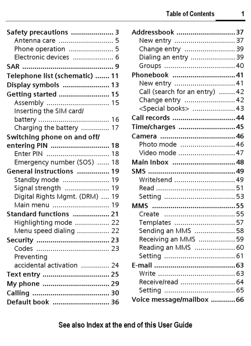
Table of contents
Other Siemens Cell Phone manuals

Siemens
Siemens SX1 User manual

Siemens
Siemens MC60 User manual

Siemens
Siemens C70 User manual

Siemens
Siemens S25 User manual

Siemens
Siemens C60 User manual

Siemens
Siemens Gigaset Gigaset S1 User manual

Siemens
Siemens C55 User manual

Siemens
Siemens A70 User manual

Siemens
Siemens CFX65 User manual

Siemens
Siemens A71 User manual

Siemens
Siemens A50 User manual

Siemens
Siemens A75 User manual

Siemens
Siemens CX75 User manual

Siemens
Siemens sx45 User manual

Siemens
Siemens C75 User manual
Siemens
Siemens S65 User manual

Siemens
Siemens A56 User manual

Siemens
Siemens SK65 User manual

Siemens
Siemens S42 User manual

Siemens
Siemens CX70 User manual