manuals.online logo
Brands
  1. Home
  2. •
  3. Brands
  4. •
  5. Siemens
  6. •
  7. Circuit Breaker
  8. •
  9. Siemens ED2 User manual

Siemens ED2 User manual

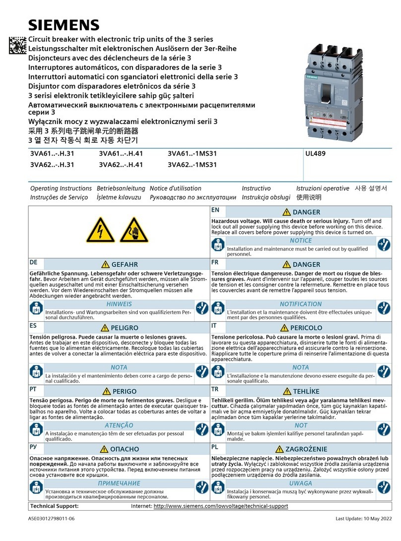
Hazardous Voltage.
Will cause death or serious injury.
Turn off and lock out all power supplying
this device before removing cover or
device and while cover is removed.
Replace the cover before power supplying this
device is turned on.
Devices: ED Frame Types ED2, ED4, HED4, ED6,HHED6,
HHED6-A and XED6 Circuit Breakers, Types ED2,
ED4, ED6 and HHED6 Molded Case Switches.
Page 1 of 4
Pc. No. 75822A04
NOTE: This instruction outlines the recommended
installation procedure.
1. General Product Information
The ED frame circuit breaker line includes Types ED2,
ED4, HED4 and ED6 Circuit Breakers; and Types D2,ED4
and ED6 Molded Case Switches.These devices are rated
15A to 125A continuous current and are available for use at
operating voltages up to 600 V.A.C. 50/60 Hz.;
240V.A.C.,400 Hz.; and 250 V.D.C.
The ED frame circuit breaker line also includes Type
HHED6 Circuit Breakers; and Type HHED6 Molded Case
Switches. These devices are rated 20A to 125A continuous
current and are available for use at operating voltages up
to 600 V.A.C. 50/60 Hz.(Type ED2 Circuit Breakers and
Molded Case Switches are rated 100 A. maximum.Type
HHED6 Circuit Breakers and Molded Case Switches are rated
for A.C. 50/60 Hz. current only.) The HHED6-A and XED6
frame circuit Breakers are rated 15A continuous current and are
available for use at operating voltages up to 600Y/347V.A.C.
for 50/60 Hz.
NOTE: Molded Case Switches are available as 100 A.
and 125 A. ratings only, and are not provided with a
“Push-to-Trip” button.
For this publication, the term Circuit Breaker also includes
Molded Case Switches.
2. Installation
ED frame devices are for use in individual enclosures, panel
boards, switchboards or other approved equipment.
The installation procedure consists of inspecting, attaching
required accessories, mounting the device and connecting
and torquing the line and load wire connectors.
Mounting hardware and unmounted wire connectors (where re-
quired) are available as separate catalog items.
NOTE: Accessory installation must be completed before the circuit
breaker is mounted and connected. (See installation instructions
supplied with accessory before proceeding).
NOTE: Accessories manufactured by Siemens Energy and Auto-
mation, Inc. that are suitable for use with Circuit Breaker Types
ED2, ED4, ED6, and HED4 are also suitable and may be used
with Types HHED6, HHED6-A and XED6.
A. Turn off and lock out all power before installing or servicing.
B. Make sure that the device is suitable for the installation by
SAFETY INSTRUCTIONS
Siemens Energy & Automation, Inc.
Bellefontaine, OH 43311 U.S.A.
Installation Instructions
Interruptores termomagnéticos Marco ED,
Tipo-ED2, ED4, HED4, ED6, HHED6, HHED6-A y
XED6 é Interruptores móviles, Tipo ED2, ED4, ED6
y HHED6.
Instructivo de Instalación y Operación
Tensión peligrosa que puede causar
daños serio o la muerte, desenergice
totalmente antes de instalar o darle
servicio. Reemplace todas las barreras
y cubiertas antes de energizar el
interruptor.
INSTRUCCIONES DE SEGURIDAD
Lea cuidadosamente este instructivo, con ello obtendrá la
completa seguridad en el uso de estos equipos para su montaje.
1. Información Técnica
Generalidades
El marco ED incluye los interruptores ED2, ED4, HED4 y ED, e
interruptores móviles tipo ED2, ED4 y ED6. Estos equipos se
ofrecen para corrientes nominales desde 15A hasta 125A, son
adecuados para operar en tensiones hasta 600 V.C.A. 50/60 Hz,
240 V.C.A., 400 Hz.; y 250 V.C.D.
El marco ED tambien incluye los interruptores HHED6; y los
interruptores móviles HHED6. Estos equipos se ofrecen para
corrientes nominales de 20A a 125A, y son adecuados para operar
en tensiones hasta 600 V.C.A. 50/60 Hz.
(Los interruptores ED2 y los interruptores móviles son para
corriente nominal hasta 100 Amáximo. Los interruptores HHED6
e interruptores móviles son para usarse solo en C.A. 50/60 Hz.)
Los interruptores HHED6-A y XED6 son para 15 A corriente
nominal y una tensión hasta 600Y/347 V.C.A. a 50/60 Hz.
2. Instalación.
Los interruptores termomagnéticos ED están previstos para
alojarse en: cajas individuales, tableros de distribución, tableros
de maniobra y otros gabinetes aprobados.
Los procedimiento para la instalación consiste de: inspección de
los accesorios requeridos, montaje del interruptor y conexión de
los conductores del lado de línea y de carga. Montaje de los
conectores para cable o solerás (Cuando se requieran).
Nota: Los accesorios de instalación deben estar completos, antes
de mmontar y conectar el interruptor.
Nota: Los accesorios de instalación fabricados por Siemens
Energy son adecuados para los tipos ED2, ED4, ED6, HED4,
HHED6, HHED6-A y XED6.
A. Desenergice totalmente antes de instalarlo o darle
mantenimiento.
B.Asegúrese que el interruptor sea el adecuado para la protección
del circuito en el que se intercala, consultando las especificaciones
en la placa de características. Revise minuciosamente el
intrerruptor y verifique que no existe ningún daño antes de
instalarlo.
Peligro
Installation Instructions
Peligro
Tensión peligrosa que puede
causar daños serio o la
muerte, desenergice
totalmente antes de instalar
o darle servicio. Reemplace
todas las barreras y
cubiertas antes de energizar
el interruptor.
Instructivo de Instalación y Operación
Hazardous voltage.
Will cause death or serious
injury.
Turn off and lock out all power
supplying this device before
removing cover or device and
while cover is removed.
Replace the cover before power
supplying this device is turned on.
Page 2 of 4
Pc. No. 75822A04
comparing nameplate ratings with system requirements.
Inspect the device for completeness and check for any
damage before mounting.
C. The circuit breaker must be in "Tripped" or "OFF"
position prior to mounting.
D. To mount the device perform the following steps:
1. For individual enclosures, panelboards and switch
boards manufactured by Siemens Energy & Automation,
Inc., follow the instructions provided with this
equipment.
2. For those applications where mounting is on a flat
surface of the customers equipment, drill and tap
mounting bolt holes according to the drilling plan in
Fig. 1. For handle escutcheon cut out plans refer to Fig. 1.
NOTE: For mounting single pole breakers, the use of a
back mounting plate (Catalog Number E2BMB) is required.
3. If circuit breaker contains internal accessories, make
sure terminals can be connected when the circuit
breaker is mounted.
4. Position circuit breaker on mounting surface.
5. Install mounting screws and washers from kit Catalog
Number MSE6. Torque mounting hardware to
12-15 in-lb.[1.35-1.69 N-m].
6. After mounting the circuit breaker, line and load
terminals and accessory terminals should be
connected. Install wire connectors with correct torque
requirements. Torque values for line and load
connectors are provided on the circuit breaker
nameplate. Insure that wire and wire connectors are fully
engaged on terminals and that connectors are flush with
end of terminal.
C. El interruptor debe estar en la posición ‘disparado’ o en
posición fuera ‘off’, al instalarse.
D. Para la instalación del interruptor favor de considerar lo
siguiente.
1. Para cajas individuales, tableros de distributión, tableros de
maniobras u otros autorizados por Siemens.
2. Para aquellos casos donde el montaje es sobre una
superficie plana. Como usalmente es en estos equipos.
Perforar y roscar de acuerdo a los diagramas de la Fig. 1.
3. Si el interruptor contiene accesorios, cerciórese que las
terminales puedan conectarse cuando el interruptor esté
instalado.
4. Coloque el interruptor sobre la superficie de montaje.
5. El par de epriete para los tomillos es de 1.356 Nm o 13.83
Kg.-fcm (12 in-lb) o máximo 1.695 Nm o 17.28 Kg.-fcm
(15 in-lb).
6. Después de instalado el interruptor. La linea de
alimentación y la linea de carga deben conectarse las
terminales de los accesorios.
CIRCUIT BREAKER
MOUNTING HOLE
AND
HANDLE ESCUTCHEON
CUT OUT DIAGRAM
1 POLE
HANDLE
ESCUTCHEON
[Escantitlón
de la
manija]
[1 POLO] [2 POLOS]
2 POLES
.188 in.*
[4.77 mm] DIA.
TO ACCESS
PUSH TO TRIP
2 & 3 POLE
ONLY
#4.77 (0.188)Ø
Para el acceso
al botón pulsador
apriete para
desparar.
Sólo para 2 y
3 polos.
Diagramas de las
perforaciones de lijación y
escantillón de la manija de
los interruptores.
DRILL & TAP
#8-32* MOUNTING
HOLES
2 HOLES-2 POLES
4 HOLES-1 & 3
POLES
Peforar y roscar
#8-32
2 perforaciones
Para 2 polos,
4 perforaciones
Para 1 y 3 polos.
2.88 in.
2.30 in. 1.37 in.
.812 in.
.50 in. 1.0 in. .645 in.
2.47 in.
2.31 in.
2.20 in.
5.00 in.
1.0 in.
1.0 in.
[58.4 mm]
[12.7 mm]
[34.8 mm]
[25.4 mm]
[62.7 mm]
[58.6 mm]
[20.6mm]
[55.8 mm]
[127.0 mm]
[25.4 mm]
[25.4 mm]
[16.38 mm]
[3 POLOS]
3 POLES
[73.2 mm]
Fig. 1
Installation Instructions
Peligro
Tensión peligrosa que puede
causar daños serio o la
muerte, desenergice
totalmente antes de instalar
o darle servicio. Reemplace
todas las barreras y
cubiertas antes de energizar
el interruptor.
Instructivo de Instalación y Operación
Page 3 of 4
Pc. No. 75822A04
NOTE: When aluminum conductors are used, the
application of a suitable joint compound is recommended
to reduce the possibility of terminal overheating.
NOTE: Circuit Breakers Type HHED6, HHED6-A and
XED6 have load terminals that can rotate between two
positions. When installing wire connectors, the load terminal
must be positioned at an angle as shown in Fig. 2.
7.After the circuit breaker is installed, check all
mounting hardware for secureness.
3. Manual Operation
Manual operation of the circuit breaker is controlled by the
circuit breaker handle and the PUSH-TO-TRIP button. The
circuit breaker handle has three indicating positions, two of
which are molded into the handle to indicate ON and OFF.
The third position indicates a TRIP position and is between
the ON and OFF position. (See Fig. 3)
A. Circuit Breaker Reset
After tripping, the circuit breaker is reset by moving the
circuit breaker handle to the reset position and then
moving the handle to the ON position.
NOTE: In the event of a thermal trip, the circuit breaker
cannot be reset until the thermal element cools.
B. PUSH-TO-TRIP Button
The PUSH-TO-TRIP button checks the tripping function
and is used to manually exercise the operating mecha-
nism. (PUSH-TO-TRIP button not provided on switch)
NOTA: Cuando se usen conductores de aluminio, se
recomienda efectuar la junta adecuada para evitar la
posibilidad de sobrecalentamiento de la terminal.
7. Después de que el interruptor esté instalado, revise todos
los elementos de conexión. Revise los conectores de cables
y observe el adecuado par de apriete, los de la línea y de la
carga, indicado en la placa de características del interruptor.
3. Operación manual.
La operación de cierre y apertura del interruptor se efectúa por
medio de la manija y con el botón pulsador se logra un disparo de
prueba. La manija del interruptor tiene 3 posiciones, 2 de las
cuales están moldeadas dentro de la manija del interruptor e
indican “ON” conectado y “OFF” desconectado, la posición
“trip” disparo se encuentra entre la posición “ON” y “OFF” ver
Fig. 3.
A. Restablecer. Después de un disparo “tripping” el interruptor
debe ser restablecido, accionando la manija totalmente hacia abajo,
llevando después la manija hacia la posición de conectado “ON”.
Nota: En el caso de un disparo por sobrecarga (térmico) no podrá
serrestablecido, sino hasta que se enfríen los elementos térmicos.
B. Botón pulsador, para disparar púlsese el botón de disparo
“trip” para verificar la función de disparo y del mecanismo de
operación.
4. Revisión y prueba de campo.
Los interruptores ED, están previstos desde su diseño, para
varios años sin sevicio de mantenimiento. Acontinuación se
describe el precedimiento para revisarlo y probarlo cuando se
encuentren montados.
Fig. 2
Fig. 3
Wiring Lug Installation for
Circuit Breakers Type
HHED6 , HHED6-A and
XED6 Load terminal and
wiring lug are positioned
at an angle
On
[dentro]
Trip
[disparo]
Off
[fuera]
Reset
[restablecer]
Push-To-Trip
[botón pulsador
de disparo]
(FOR BREAKER ONLY)
Handle
[manija]
Hazardous voltage.
Will cause death or serious
injury.
Turn off and lock out all power
supplying this device before
removing cover or device and
while cover is removed.
Replace the cover before power
supplying this device is turned on.
Installation Instructions
Peligro
Tensión peligrosa que puede
causar daños serio o la
muerte, desenergice
totalmente antes de instalar
o darle servicio. Reemplace
todas las barreras y
cubiertas antes de energizar
el interruptor.
Instructivo de Instalación y Operación
4. Inspection and FieldTesting
ED-frame circuit breakers are designed to provide years of
maintanance free service. The following procedure outlines
how to inspect and test a circuit breaker in service.
Inspection and Maintenance
Circuit breakers in service should be inspected periodically.
The inspection should include the following steps:
A. Turn off and lock out power before inspecting or
servicing. Special attention should be paid to reverse
feed applications to ensure no voltage is present.
B. Remove dust, soot, grease or moisture from the
surface of the circuit breaker using a lint free cloth
brush or vacuum cleaner. DO NOT blow debris into
the circuit breakers. If contamination is found, eliminate
the source of the problem.
NOTE: Do not spray or allow any petroleum based
chemicals, solvents or paints to contact the inside or
outside of breaker or electrical connections.
C. Switch the circuit breaker to the ON and OFF positions
several times to be sure the mechanical linkages are
free and do not bind. If mechanical linkages are not
free, replace the circuit breaker.
D. Press the PUSH-TO-TRIP button to mechanically trip
the circuit breaker. Trip, reset, and switch the breaker
on several times. If the circuit breaker cannot be turned
on replace the circuit breaker.
E. Check circuit breaker housing and handle for cracks,
chipping and discoloration. Circuit breakers should
be replaced if cracks or severe discoloration is found.
F. Check terminals and wire connectors for looseness
or signs of overheating. Overheating will show as discol-
oration, melting or blistering of conductor insulation, or
as pitting or melting of conductor surfaces due to arcing.
If there is no evidence of overheating or looseness,
do not disturb or tighten the connections. If there is
evidence of overheating, terminations should be
replaced. Before re-energizing the circuit breaker, all
wire connectors and cable should be refurbished to
the original installed condition.
IMPORTANT: Refer to instructions on page 2, Item 6.
G. Check circuit breaker mounting hardware. Tighten if
necessary.
H. Check area where circuit breaker is installed for any
safety hazards, including personal safety and fire
hazards. Exposure to certain types of chemicals can
cause deterioration of electrical connections.
Field Testing
Any field testing should be conducted in accordance
with NEMA Standards Publication AB2.
Revisión.
Los interruptores ya montados deben reviarse periódicamente.
La revisión se realiza de la siguiente forma:
A. Desenergice totalmente el interruptor antes de revisar a darla
servicio, prestando especial atención a la ausencia de cual;quier
votaje inverso.
B. Remueva polvo, suciedad, grasa o cochambre de la superficie
del interruptor, con una franela libre de pelusas, brocha o
asperadora.
Nota: No use aire a presión, pues pueden introducirse
particulas al interior. Si se encuentra contaminación elimine la
fuente de esta problema. No use aerosoles, ni permita que
derivados químicos del petróleo, solventes o pinturas, se pongan
en contacto con las conexiones eléctricas dentro o fuera del
interruptor.
C. Accione la manjia varias veces, conectando y desconectando,
para asegurarse que los elementos mecánicos están libres y no
presentan trabazón, si nota que los mecánismos no actúan
libremente, sustituya el interruptor.
D. Oprima el botón de disparo ‘trip’ restablezca y accione la
manija varias veces. Si no se consigue que la manija retorne a la
posición conectado ‘ON’, sustituya el interruptor.
E. Revise exteriormente el interruptor, observe que la caja y la
manija no presentan roturas, despostillado o decoloración. El
interruptor debe ser sustituido si presenta fuerte decoloración o
cualquierea de las anomalias mencionadas.
F. Revise las terminales los conectores de los cables, observando
cualquier indicación de falsos contactos o sobrecalentamientos.
Los sobrecalentamientos muestran decoloración, fusión o
rugosidades del aislamiento del conductor, los falsos contactos,
escoreaduras o fusión de las superficies del conductor ocasionadas
por arqueos. Si no hay evidencia de sobrecalentamientos o falsos
contactos, no altere ni apriete las conexiones. Si hay evidencia de
sobrecalentamiento las terminales deben reemplazarse.Antes de
reenergizar el interruptor, todos los conectores de cable y cables
deben ser colocados en las condiciones originales del interruptor.
G. Revise los elementos de conexión, apriete si es necesario.
H. Revise que el área donde se instalará el interruptor, este libre
de riesgos, inclusive para seguirdad del personal y para evitar
riesgos de incendio. La exposición a ciertos tipos de productos
quimicos, pueden causar deterioro de las conexiones eléctricas.
Page 4 of 4
Pc. No. 75822A04© Siemens Energy & Automation, Inc. 1993
Manufactured Under One or More of the Following
U.S. Patents: 4,594,567; 4,595,896; 4,675,640; 4,680,564.
Hazardous voltage.
Will cause death or serious
injury.
Turn off and lock out all power
supplying this device before
removing cover or device and
while cover is removed.
Replace the cover before power
supplying this device is turned on.

This manual suits for next models

14

Other Siemens Circuit Breaker manuals

Siemens 3WN6 User manual

Siemens

Siemens 3WN6 User manual

Siemens SIRIUS 3RA1.5 User manual

Siemens

Siemens SIRIUS 3RA1.5 User manual

Siemens NEB Series User manual

Siemens

Siemens NEB Series User manual

Siemens 3VA51 ED Series User manual

Siemens

Siemens 3VA51 ED Series User manual

Siemens SIRIUS 3RV1.2 Series User manual

Siemens

Siemens SIRIUS 3RV1.2 Series User manual

Siemens 3VF Series Use and care manual

Siemens

Siemens 3VF Series Use and care manual

Siemens 3WX31 83-8 Series User manual

Siemens

Siemens 3WX31 83-8 Series User manual

Siemens SENTRON 3WA Air User manual

Siemens

Siemens SENTRON 3WA Air User manual

Siemens 3VA20-H 3 Series User manual

Siemens

Siemens 3VA20-H 3 Series User manual

Siemens 3AH3 User manual

Siemens

Siemens 3AH3 User manual

Siemens I-T-E Sensitrip MD Series Owner's manual

Siemens

Siemens I-T-E Sensitrip MD Series Owner's manual

Siemens GM-SG User manual

Siemens

Siemens GM-SG User manual

Siemens SIRIUS 3RV1611-0BD10 User manual

Siemens

Siemens SIRIUS 3RV1611-0BD10 User manual

Siemens 5ST303 Series User manual

Siemens

Siemens 5ST303 Series User manual

Siemens 3WX3647-5JE00 User manual

Siemens

Siemens 3WX3647-5JE00 User manual

Siemens CLM0D Series Assembly instructions

Siemens

Siemens CLM0D Series Assembly instructions

Siemens SENTRON 3VA1 User manual

Siemens

Siemens SENTRON 3VA1 User manual

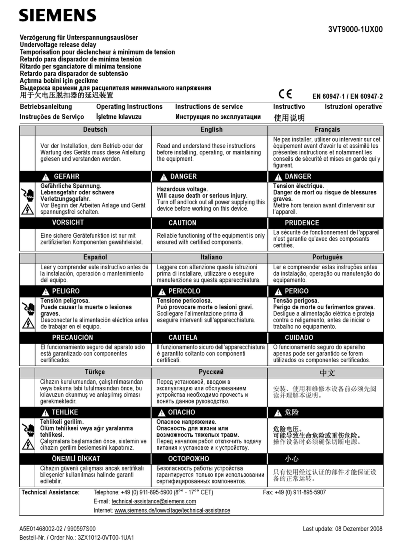
Siemens 3VT9000-1UX00 User manual

Siemens

Siemens 3VT9000-1UX00 User manual

Siemens PL 50 User manual

Siemens

Siemens PL 50 User manual

Siemens 3VT9215-4TD30 User manual

Siemens

Siemens 3VT9215-4TD30 User manual

Siemens 3VT9300-4WN00 User manual

Siemens

Siemens 3VT9300-4WN00 User manual

Siemens ETU745 User guide

Siemens

Siemens ETU745 User guide

Siemens GMSG-GCB User manual

Siemens

Siemens GMSG-GCB User manual

Siemens 3WL10 Series User manual

Siemens

Siemens 3WL10 Series User manual

Popular Circuit Breaker manuals by other brands

Eaton IZM32 instruction manual

Eaton

Eaton IZM32 instruction manual

Eaton IZM97 instruction manual

Eaton

Eaton IZM97 instruction manual

Eaton NZM1-XFI30U Instruction leaflet

Eaton

Eaton NZM1-XFI30U Instruction leaflet

ABB K-Line 225A Installation & maintenance instructions

ABB

ABB K-Line 225A Installation & maintenance instructions

DACO ACB manual

DACO

DACO ACB manual

Doepke DFS 4 A EV Installation and operating manual

Doepke

Doepke DFS 4 A EV Installation and operating manual

Eaton Power Defense installation instructions

Eaton

Eaton Power Defense installation instructions

GE SecoVac Series manual

GE

GE SecoVac Series manual

Leviton GCA20 installation instructions

Leviton

Leviton GCA20 installation instructions

CHINT AX-5 quick start guide

CHINT

CHINT AX-5 quick start guide

Eaton P3-63/I4 Instruction leaflet

Eaton

Eaton P3-63/I4 Instruction leaflet

Eaton DILM32-XRL-PI Instruction leaflet

Eaton

Eaton DILM32-XRL-PI Instruction leaflet

Bticino MA-MH160 instruction sheet

Bticino

Bticino MA-MH160 instruction sheet

Westinghouse F-122 Instruction book

Westinghouse

Westinghouse F-122 Instruction book

Doepke DFS 4 B SK series Installation and operating manual

Doepke

Doepke DFS 4 B SK series Installation and operating manual

ABB SACE Emax 2 E2.2 Installation, operation and maintenance instructions for the installer and the user

ABB

ABB SACE Emax 2 E2.2 Installation, operation and maintenance instructions for the installer and the user

Eaton P3 E(+SVB) Series Instruction leaflet

Eaton

Eaton P3 E(+SVB) Series Instruction leaflet

Eaton EG-DC Series Instruction leaflet

Eaton

Eaton EG-DC Series Instruction leaflet

manuals.online logo
manuals.online logoBrands
  • About & Mission
  • Contact us
  • Privacy Policy
  • Terms and Conditions

Copyright 2025 Manuals.Online. All Rights Reserved.