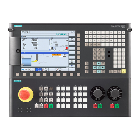
Siemens SINUMERIK 840D Operating instructions
Other Siemens Control Unit manuals
Siemens
Siemens SINUMERIK MC Quick start guide
Siemens
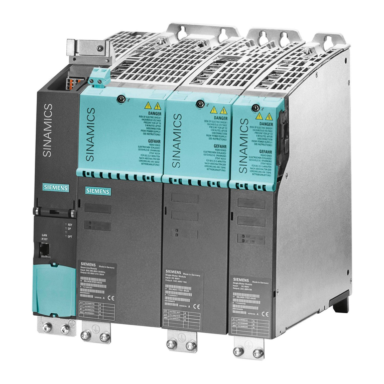
Siemens SINAMICS S120 Technical Document

Siemens
Siemens 3VA9908-0BC Series User manual
Siemens
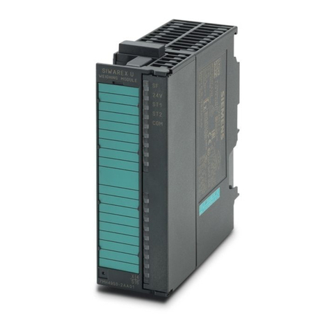
Siemens Siwarex U Application guide

Siemens
Siemens SINUMERIK 840D sl User manual
Siemens
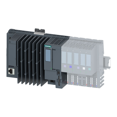
Siemens SIMATIC CPU 1515SP PC2 F User manual
Siemens
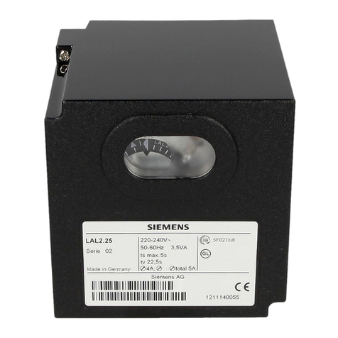
Siemens LAL Series User manual
Siemens
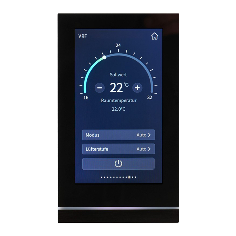
Siemens GAMMA instabus Touch control TC5 User manual
Siemens
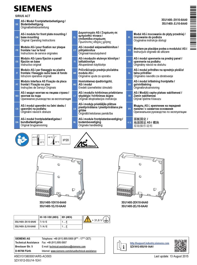
Siemens SIRIUS ACT 3SU1400-1EK10-6AA0 User manual
Siemens
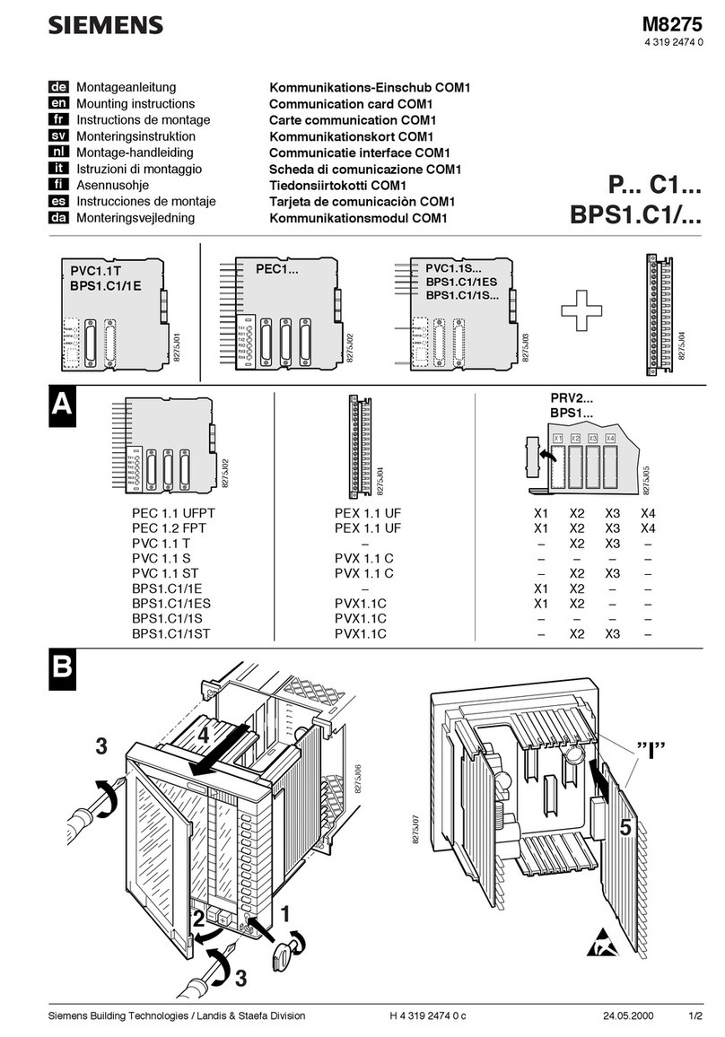
Siemens P Series User manual
Siemens
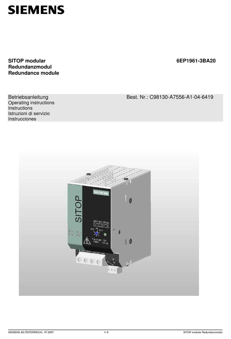
Siemens SITOP modular 6EP1961-3BA20 User manual

Siemens
Siemens LOGO! CIM User manual
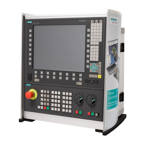
Siemens
Siemens SINUMERIK 840D sl User manual
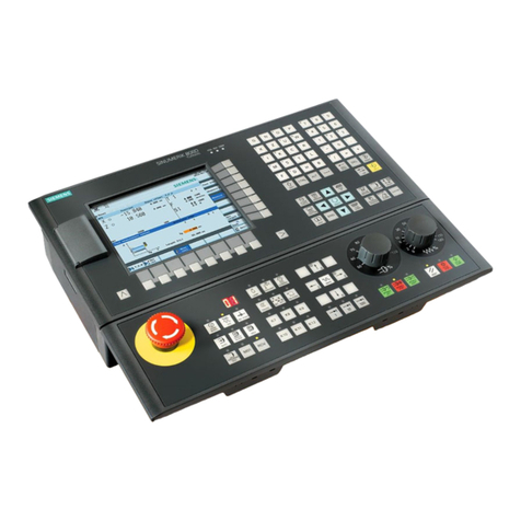
Siemens
Siemens SINUMERIK 808D User manual
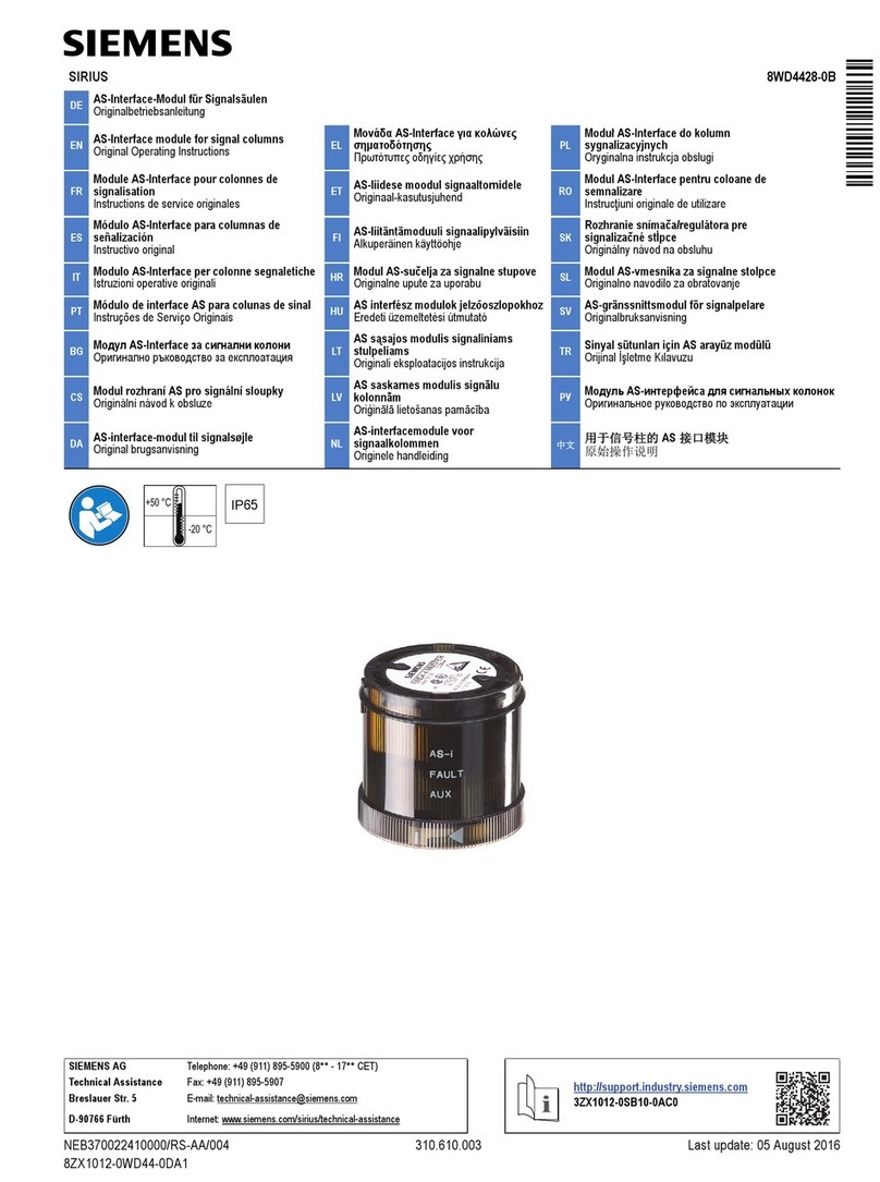
Siemens
Siemens SIRIUS 8WD4428-0B User manual
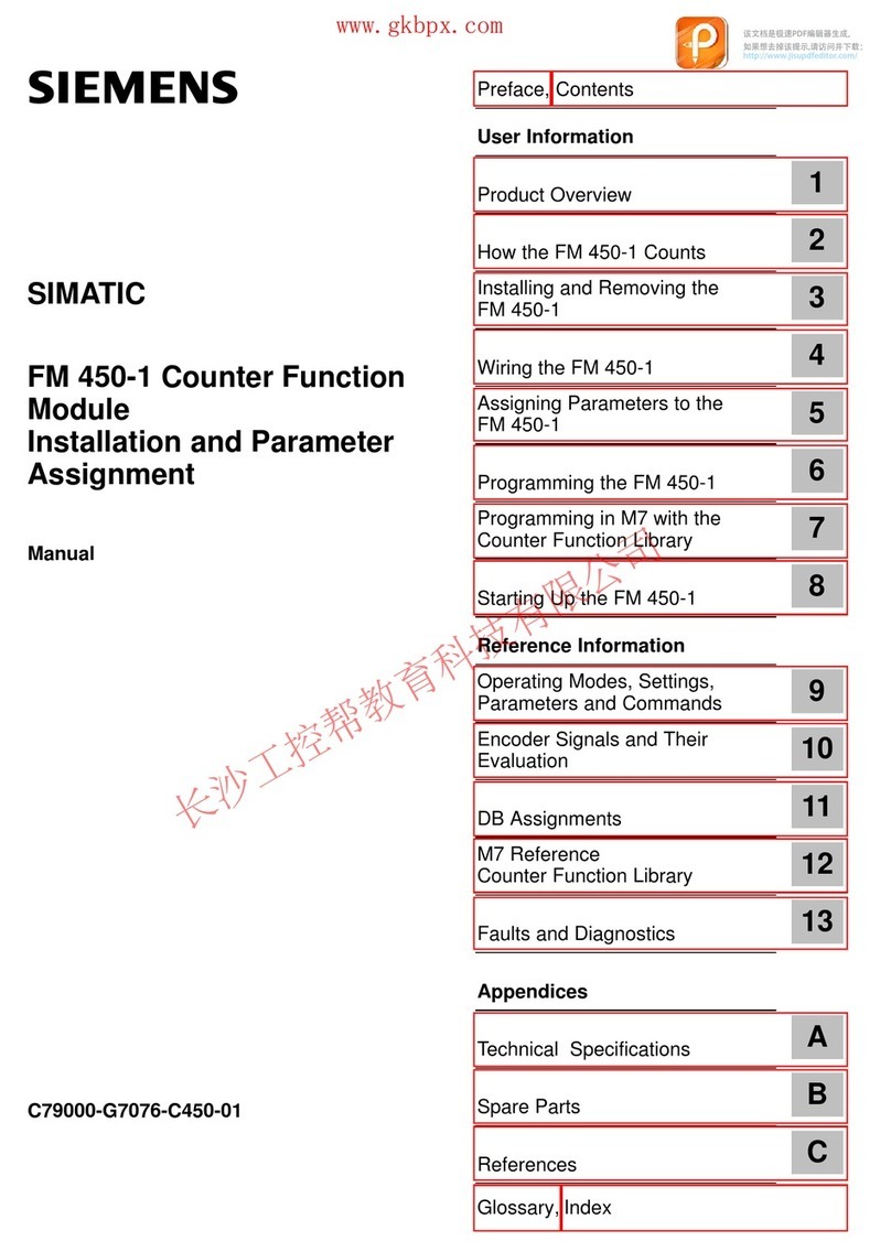
Siemens
Siemens SIMATIC FM 450-1 User manual
Siemens
Siemens SIMATIC RF120C User manual

Siemens
Siemens SINAMICS G130 User manual
Siemens
Siemens SINUMERIK 840D Parts list manual
Siemens
Siemens Climatix POL822 User manual
Popular Control Unit manuals by other brands

Festo
Festo Compact Performance CP-FB6-E Brief description

Elo TouchSystems
Elo TouchSystems DMS-SA19P-EXTME Quick installation guide

JS Automation
JS Automation MPC3034A user manual

JAUDT
JAUDT SW GII 6406 Series Translation of the original operating instructions

Spektrum
Spektrum Air Module System manual

BOC Edwards
BOC Edwards Q Series instruction manual

KHADAS
KHADAS BT Magic quick start

Etherma
Etherma eNEXHO-IL Assembly and operating instructions

PMFoundations
PMFoundations Attenuverter Assembly guide

GEA
GEA VARIVENT Operating instruction

Walther Systemtechnik
Walther Systemtechnik VMS-05 Assembly instructions

Altronix
Altronix LINQ8PD Installation and programming manual
