manuals.online logo
Brands
  1. Home
  2. •
  3. Brands
  4. •
  5. Siemens
  6. •
  7. Controllers
  8. •
  9. Siemens DOL Series User manual

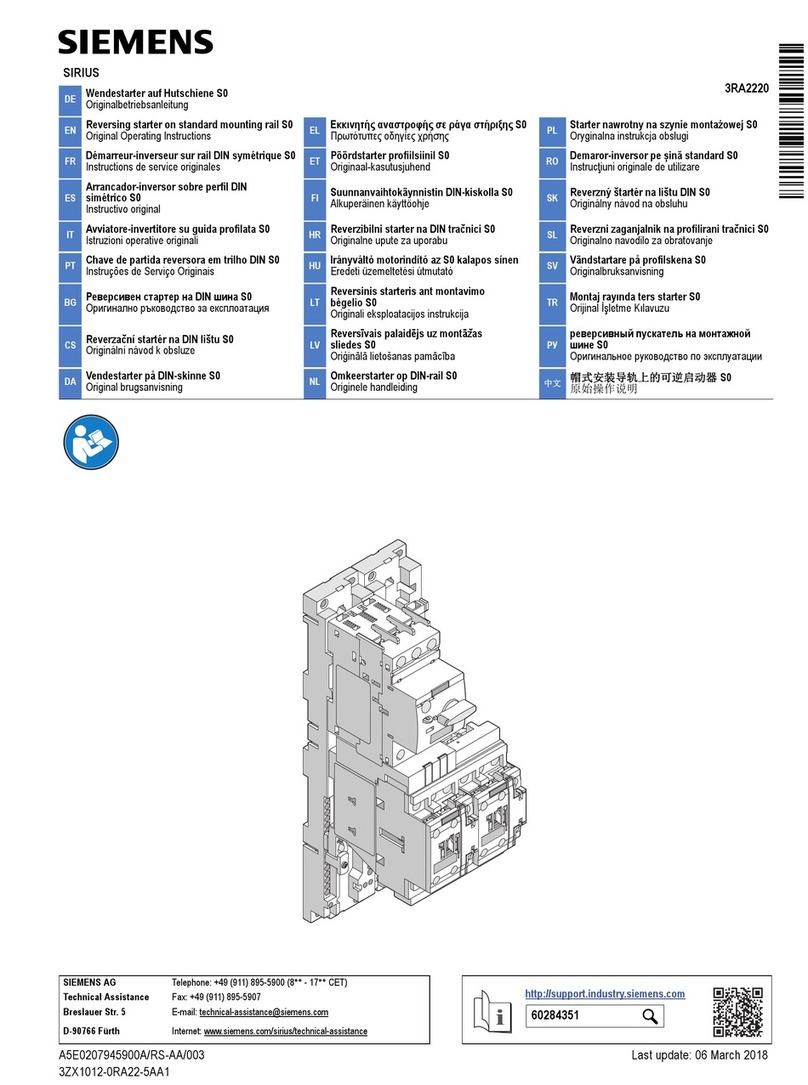
Siemens DOL Series User manual

Direct-On-Line and Automatic Star – Delta Starter
Our new series of DOL and ASD starters complies to latest
standard IS/IEC 60947-4-1
Operating Instructions
Selection:
• ReferTable1forrecommended
selectionofDOLStartersand
Table2forASDStarters.
• DOLandASDStartersare
suppliedwithoutrelays.Relays
aretobettedatsite.
• Selectthesuitablerangeof
relayasperrecommendation
giveninTable1and2.
• Selectback-upfuserating
fordifferentstartersfrom
theselectiontables.The
recommendationofthefuses
andfuseswitchesisaccording
toType-2co-ordinationasper
IS/IEC60947-4-1.
Inspection:
• Removethehousingcover.
• Checkthecoilvoltagessothat,
thecoilvoltagecorrespondsto
actualsupplyvoltage.
Fig.2Direct-On-LineStarter(DOL)
Fig.3AutomaticStarDeltaStarter
(ASD)
• Inspectinteriorforbreakage.
• Ifyoundaseriousdefect,do
notusetheproductbuthave
itcheckedbyanauthorized
Siemensdealeroran
electrician.
Installation:
• Assoonasyouopenthe
starter,youwillseeasticker
“K1BIRELAY”showingthe
locationatwhichtherelay
shouldbemounted.Refer
Table5fortheprocedureto
befollowedforfittingthe
relay.
• Completethewiringby
connectingthewireshaving
ferrules‘95’and‘96’.Wiring
shouldbeexactlyasperthe
circuitdiagramlabelshown
oninsideofthefrontcover.
• Backupfuseratingsandcable
sizesarealsorecommended
onthelabel.Alsoforyour
futurereference,spaceis
providedonthelabelinside
thefrontcovertowritethe
coilvoltageandtherelay
rangeselectedbyyou.
• Incaseofstartershaving
resettingcord,attachthe
resettingdeviceontheholes
providedontherelaysurface.
(ref.fig.4)Adjusttheend
oftheresetcordusingthe
adjustmentscrew(fig.4)so
thatclearancebetweenblue
knobandresetcordmetallic
endisabout2mm.
Fig.1NewseriesofStarters
Fordependableservice,itisofutmostimportancethatinstructionsgivenbelowarefollowedfor
selection,inspection,installation,commissioning,operationandmaintenance.
s
Hazardous Voltage can cause
Electric Shock and burns.
DisconnectPowerbeforeproceeding
withanyworkonthisequipment
Warning:
Removerequiredlengthof
insulationandusingthe
hardwareconnectedatthe
contactorterminals,fixthe
incomingandoutgoing
cables.
c. Incase,thepowerandcontrol
circuitsareofdifferent
voltages,connectthedesired
supplytothecontrolcircuit,
usingtheconnector.Follow
theinstructionsgivenon
wiringdiagramlabelstuckon
innersideoffrontcover.
d. Tightenthescrewsfirmly.
e. Checkthatthelineandmotor
connectionsaredoneexactly
asperwiringdiagrampasted
insidethefrontcover.
f. Removeanywirecutting
fallenintothestarter.
• Connectearthingconductorto
terminalsmarked
Commissioning:
Read the caution
note carefully before
commissioning.
• Removethefrontcover.
• BeforeswitchingON,re-check
externalconnections.
• Setoverloadrelayto0.58
timestheratedmotorcurrent.
• Setthedialofthetimer(fig.
7)toanapprox.valueof
startingtimeofyourmotor
(preferablymorethan6sec.).
• Star-DeltaTimersetting(for
ASDonly):
a. Firststartthemotorby
pressingthe‘ON’buttonas
indicatedinfig.8.
b. Measuretimetakenforitto
• Mountstarteronavertical
wall/platefreefrom
vibrations,withpropernuts
andbolts.Referfig.11for
mountingdimensions,and
alsofig.5forpermissible
displacement.
Fig.5 Maximumpermissible
displacementfromverticalplane
Fig.6Cableconnections
Fig.4ResetCordconnections
'Reset'
Cord
reachnearlyratedspeedor
steadystatecurrent(indicated
whenmotorhumreachesa
steadypitch).
c. Stopthemotor.Settimertothis
measuredvalue,byrotatingthe
dialshowning.7.
• Overloadrelaysetting:
a. Forcloserprotectionsetthe
overloadrelaytoactualline
current(DOL)oractualphase
current(ASD)asmeasuredby
anAmmeter.
• IntheabsenceofanAmmeter,
useprocedureasgivenbelow:
a. Startthemotorandletitrun
for½anhour.Thengradually
reducerelaysettingtillittrips.
Setrelayataslightlyhigher
valueofthissetting.
b.Allowresettimeofapprox.
4min.Presstheblueknobon
therelaycompletelytoreset
therelay.
c.Re-startmotoraftersome
time.Iftherelaydoesnottrip,
considerittobeproperlyset.
Ifittrips,followstepbwith
settingatalittlehighervalue
andrecheck.
d. Overloadrelaycharacteristics
giveninfig.10canbeusedto
estimatetheaveragetripping
timeatdifferentmultiplesof
setcurrent.
Caution:
• Switch off the starter and
disconnect the main supply
by switching off the main
switch before doing any
maintenance.
Screw for
adjustment
2
Fig.7TimerAdjustment
Dial
• Selectcorrectsizesofcableas
specifiedinselectionTable1
and2.
• Dependinguponlocation
ofincomingandoutgoing
cablesremovecorresponding
rubbergrommets.Ensuredust
proofingbyusingpropercable
gland.(fig.6)
a. Forcontactorsupto3TS36,
removeapprox.10mmof
insulationoftheconductor,
loosenterminalscrews
andpushcableendunder
theSIGUTterminalofthe
contactor.
b. Forcontactorsabove
3TS36,selectproperlugs
forconductortermination
dependinguponcablesize
specifiedinTable1and2.
H - Hand Reset
A - Auto Reset
Blue
Reset
Knob
• In case of DOL starters
under no circumstances
should the relay be set
higher than the rated
current on the motor name
plate.
• In case of ASD starters
under no circumstances
should the relay be set
higher than phase current
i.e. 0.58 times the rated
current on the motor
nameplate.
• Iftherelaytripsevenwhen
set at the rated motor
current the suitability of
the starter / relay for the
particular application should
be checked with the nearest
Siemens office.
Operating Characteristics:
Thegivencharacteristics
(fig.10)areaveragevaluesof
allrangesandsizesofbimetal
relaysandaremainlyintendedto
indicatetheinversetimecurrent
characteristicsofthesame.The
trippingtimesshownarefor
relaysstartingfromthecold
state.Atoperatingtemperatures
(heatedatratedcurrent)these
arereducedtoabout25%of
thevaluesobtainedfromthe
characteristics.
Operation:
• Forstartingthemotor,press
greenpushbutton,marked‘I’
(fig.8).
• Forstoppingthemotor,press
redpushbutton,marked‘O’
(fig.8).
• Incaseofhandresettype
overloadrelay,pressblue
pushbutton,marked‘R’(fig.
8)forresetting,aftertherelay
hastrippedduetooverload.
Inthiscaseyoucanrestart
themotoronlyifyouresetit.
• Incaseyouwantthestarter
tobein‘SelfReset’mode,
theblueknobonrelay(fig.
9)istobepressedand
rotatedinanticlockwise
direction;sothatitcomes
inposition‘A’,anditsedge
Fig.8Starterfrontview
Fig.9Relayfrontview
Fig.10Operatingcharacteristicsof3US5/6relays
Maintenance:
• Keeptheinteriordustfree.
• Re-tightenterminalscrews
fromtimetotime.
• Nomaintenanceisrequired
foroverloadrelayandpush
button.Donotopenthem.
• Blackeningofsilvercoated
/alloyedcontactsdoesnot
affectoperationallife.If
necessary,cleanthecontacts
ofcontactorwithCRC2-26.
Removeglobuleswith
scrapperorscrewdriverwith
minimumforce.Underno
circumstancesthecontact
shouldbefiledordressedas
itwillreducetheelectricallife
drastically.
• Ifthecontactorhums,clean
themagnetpolefaceswith
softcloth.
• Replacecontactsofthe
contactoriftheyare
severelypittedorwhen
only40%originalcontact
tipremains.Fordetailsof
contactormaintenancerefer
toour‘GuidetoContactor
Installation&Maintenance’.
'ON'
button
'OFF'
button
'RESET'
button
3
flushwiththerelaysurface.
Inthismodeeveniftherelay
tripsonoverload,itwillbe
automaticallyresetinmax.
4minutes.Themotorcanbe
restartedonlyaftertherelay
isreset.
3 US 5/6 3 US 5/6
Selection Table 1: Direct-On-Line Starters
Motor
Output
at 415V,
3ph, 50Hz
I()
4 Pole
motor
Size
DOL Starters Contactor RecommendedOver-load
Relay 50°C
Recommended Fuse-
Switch Recommended
Cu cable size
Type Reference1) Type Reference1) Type Range Type
Max. Backup
HRC Fuse
Rating
(kW/HP) (A) (A) (A) (mm2)
11/15 20.8 DOL-1 3TW7493-2A.. 3TS3400-0A.. 3US5200-2C8K 16-25 3KL815 50 6
15/20 28 DOL-2 3TW7494-2A.. 3TS3522-0A.. 3US5600-2D8K 20-32 3KL815 50 6
18.5/25 34 3TW7495-2A.. 3TS3622-0A.. 3US5600-2Q8K 25-36 3KL815 63 10
22/30 40
DOL-3
3TW7496-2A.. 3TS4722-0A.. 3US5800-2F8K 32-50 3KL821 80 16
30/40 53 3TW7497-2A.. 3TS4822-0A.. 3US5800-2T8K 40-57 3KL821 100 16
37/50 65 3TW7498-2A.. 3TS4822-0A.. 3US5800-2V8K 57-70 3KL822 125 25
45/60 78 DOL-6 3TW7499-2A.. 3TS5122-0A.. 3US5800-8Y8K 70-95 3KL822 125 35
55/75 96 3TW7590-2A.. 3TS5122-0A.. 3US5800-5C8K 85-105 3KL823 160 35
1)10thand11thplaceinthetypereferenceisforcoilvoltagecode,referTable3.
Selection Table 2: Automatic Star-Delta Starters
Motor
Output
at 415V,
3ph,
50Hz
I()
4 Pole
motor
line
current
I()
4 Pole
motor
phase
current
Size
ASD Starters Contactor
Main
Contactor
Star
Contactor
Delta
Recommended
Over-loadRelay50°C
Recommended
Fuse-Switch
Recommended
Cu cable size
Type
Reference1)
Type
Reference1)
Type
Reference1)
Type
Reference1) Type Range Type
Max.
Backup
HRC Fuse
Rating
Incoming
(from
supply)
Outgoing
(to
motor)
(kW/HP) (A) (A) (A) (mm2)(mm2)
22/30 40 23.2
ASD-2
3TE7493-2A… 3TS3522-0A.. 3TS3511-0A.. 3TS3511-0A.. 3US5600-2C8K 16-25 3KL815 50 16 10
30/40 53 30.6 3TE7494-2A… 3TS3522-0A.. 3TS3511-0A.. 3TS3511-0A.. 3US5600-2D8K 20-32 3KL815 63 16 10
37/50 65 37.5 3TE7495-2A… 3TS3622-0A.. 3TS3511-0A.. 3TS3611-0A.. 3US5600-2R8K 32-40 3KL821 80 16 10
45/60 78 45 ASD-3 3TE7496-2A… 3TS4722-0A.. 3TS3522-0A.. 3TS4722-0A.. 3US5800-2F8K 32-50 3KL821 100 35 16
55/75 96 55.4 3TE7497-2A… 3TS4822-0A.. 3TS3522-0A.. 3TS4822-0A.. 3US5800-2T8K 40-57 3KL821 100 35 25
1)10thand11thplaceinthetypereferenceisforcoilvoltagecode,referTable3.
4
Selection Table 3
Coil Voltage 10th - 11th digit in MLFB
24V B0
110V F0
230V P0
240V U0
415V R0
Allothervoltages Uponenquiry
Selection Table 4
Star-Delta Timer
Input Voltage MLFB
24/100-127V 3RP1576-1NQ308K
200-240V 3RP1576-1NM208K
380-440V 3RP1576-1NM208K
Timer to be selected according to contactor coil voltage.
Spares List
Type of spares MLFB
ON/OFFActuator 3SX155-21YA
ON/OFFContact(DOL2&ASD2) 3SX155-11YA
ResetcordforASD3 3UX1015
Accessoryfor3US58independent
mounting
3UX1421
ContactBlock(1NO) 3SB5420-0B
ContactBlock(1NC) 3SB5420-0C
ContactorSpareContactKit ReferSiemensPriceList
ElectronicStar-DeltaTimer ReferTable4
Relay ReferTable1&2
Contactor ReferTable1&2
Aux.contactblockfor3TS34 3TX4010-2A
Tightening Torque
DOL
& ASD
Starter
Incoming
terminal
Tightening
Torque
Outgoing
Terminal
Tightening
Torque
DOL1 M4 1.0-1.5Nm M4 1.0-1.5Nm
DOL2 M4 1.0-1.5Nm M5 2.5-3.0Nm
DOL3 M6 3.0-4.0Nm M5 2.5-3.0Nm
DOL6 M6 3.0-4.0Nm M5 2.5-3.0Nm
ASD2 M4 1.0-1.5Nm M4 1.0-1.5Nm
ASD3 M6 3.0-4.0Nm M6 3.0-4.0Nm
Cover xing torque 1.5-2.1Nm.
40
Table 5: Installation
Starter MLFB Mode of Relay
mounting Procedure
DOL1/2
3TW7493-2A..
Directmountingon
contactor
1. Unscrewcontactorterminalsandputtherelayterminalsundercontactorterminals.
3TW7494-2A.. 2. Engagetherelayhookincontactorslot.
3TW7495-2A.. 3. Pushtherelaytowardscontactorasmuchaspossible,sothattherelayedgeisush
withthecontactorribs.
ASD2
3TE7493-2A.. 4. Tightenthecontactorterminalscrews.
3TE7494-2A..
3TE7495-2A..
DOL3
3TW7496-2A..
Ontheterminal
carrier
1. Replacetheterminalsofrelaybythoseprovidedinthehardwarekitalongwiththe
starter.
3TW7497-2A.. 2. SeethediagramgivenintheOperatingInstructionsofaccessoryforindependent
mounting.
3TW7498-2A.. 3. Loosenthescrewsofaccessoryforindependentmounting.
ASD3
3TE7497-2A.. 4. Puttherelayterminalsbelowthepintypelugsofthecableterminations.
5. HoldtherelaythewayitisshownintheOperatingInstructionsofterminalcarrier
andengagetherelayhookintheslotoftheterminalcarrier.
6. Whentherelayedgeisushwithterminalcarrieredge,clamptherelaywithtermi-
nalcarrierusingtheclampsinthehardwarekit.
7. Tightentheterminalcarrierscrews.
DOL6
3TW7499-2A..
Directmountingon
contactor
1. Engagetherelayhookincontactorslot.
3TW7590-2A.. 2. Alignthecontactorterminalholestorelayterminalholes.
3. Fixtherelaytothecontactorusingthehardwarealreadyttedatthecontactor
terminals.
4. Fixtheterminalsprovidedalongwiththerelaytotheotherside(outgoingside)of
therelayandusethehardwareprovidedforcableconnections.
5
DOL 1/2
3TW7493-2A..
3TW7494-2A..
3TW7495-2A..
DOL 3
3TW7496-2A..
3TW7497-2A..
3TW7498-2A..
DOL 6
3TW7499-2A..
3TW7590-2A..
s
Fig. 11: Dimensional Details
6
ASD 2
3TE7493-2A..
3TE7494-2A..
3TE7495-2A..
ASD 3
3TE7496-2A..
3TE7497-2A..
7
Siemens Ltd.
XXX-XX-XXX-XXX
This replaces SGR-01-115-029
'Productdevelopmentisacontinuousprocess.Consequently
thedataindicatedinthisleaetissubjecttochangewithout
priornotice.ForlatestissuecontactourSalesOfce.'
A5E45312503A/AA
CustomerCareTollfreeno.1800220987Email:adscs.india@siemens.com
PLASTICS:Segregateaspermaterialtypeforrecycling
throughauthoriseddealer.
BecauseofthelonglifetimeofSiemensproductsthe
disposalguidelinesmaybereplacedbyothernational
regulationswhentakingtheproductoutofservice.
Thelocalcustomercareserviceisavailableatanytime
toanswerdisposal-relatedquestions
SiemensProductsareenvironmentfriendly,which
predominantlyconsistofrecyclablematerials.
Fordisposalwerecommenddisassemblingand
separationintofollowingmaterials:
METALS:SegregateintoFerrous&NonFerroustypesfor
recyclingthroughauthoriseddealer.
Disposal
AB

This manual suits for next models

7

Other Siemens Controllers manuals

Siemens GLB111.9E/MO User manual

Siemens

Siemens GLB111.9E/MO User manual

Siemens Simatic S7-300 User manual

Siemens

Siemens Simatic S7-300 User manual

Siemens RDU340 Series Operator's manual

Siemens

Siemens RDU340 Series Operator's manual

Siemens Reyrolle 7SR45 User manual

Siemens

Siemens Reyrolle 7SR45 User manual

Siemens 1PL618 Series User manual

Siemens

Siemens 1PL618 Series User manual

Siemens Sirius 3RA6 User guide

Siemens

Siemens Sirius 3RA6 User guide

Siemens CP-8000 User manual

Siemens

Siemens CP-8000 User manual

Siemens SIPROTEC 7SJ61 User manual

Siemens

Siemens SIPROTEC 7SJ61 User manual

Siemens RUGGEDCOM WIN5123 User manual

Siemens

Siemens RUGGEDCOM WIN5123 User manual

Siemens SSD161S.05DU User manual

Siemens

Siemens SSD161S.05DU User manual

Siemens SIMATIC NET CP 1613 A2 User manual

Siemens

Siemens SIMATIC NET CP 1613 A2 User manual

Siemens SINAMICS S120 User guide

Siemens

Siemens SINAMICS S120 User guide

Siemens 3TW7291-1A Guide

Siemens

Siemens 3TW7291-1A Guide

Siemens SIMATIC S5 Series User manual

Siemens

Siemens SIMATIC S5 Series User manual

Siemens RLM162 User manual

Siemens

Siemens RLM162 User manual

Siemens OpenAir GDB181.1E/3 User manual

Siemens

Siemens OpenAir GDB181.1E/3 User manual

Siemens RWD68 User manual

Siemens

Siemens RWD68 User manual

Siemens SIMATIC TI555 User guide

Siemens

Siemens SIMATIC TI555 User guide

Siemens GEB 1 Series Installation guide

Siemens

Siemens GEB 1 Series Installation guide

Siemens SINAMICS G120 User guide

Siemens

Siemens SINAMICS G120 User guide

Siemens Simatic S7-1500 User manual

Siemens

Siemens Simatic S7-1500 User manual

Siemens SIRIUS 3RW40 User manual

Siemens

Siemens SIRIUS 3RW40 User manual

Siemens SIMATRIX Owner's manual

Siemens

Siemens SIMATRIX Owner's manual

Siemens SSD31 Series User manual

Siemens

Siemens SSD31 Series User manual

Popular Controllers manuals by other brands

Moen AS-4200 installation guide

Moen

Moen AS-4200 installation guide

Nortek WRC2 Installation instructions & owner's manual

Nortek

Nortek WRC2 Installation instructions & owner's manual

Chino KP1000 manual

Chino

Chino KP1000 manual

Fulham Hotspot FHSCP-UNV Series Installation and operation instructions

Fulham

Fulham Hotspot FHSCP-UNV Series Installation and operation instructions

Binks HGB-509-5-R38 Operator's manual

Binks

Binks HGB-509-5-R38 Operator's manual

NDS SUN CONTROL 2 user manual

NDS

NDS SUN CONTROL 2 user manual

RIB PARK 230V fw08 manual

RIB

RIB PARK 230V fw08 manual

Titan Controls SPARTAN Series instruction manual

Titan Controls

Titan Controls SPARTAN Series instruction manual

Elcometer SAGOLA 4120 PLUS instruction manual

Elcometer

Elcometer SAGOLA 4120 PLUS instruction manual

BENDIX EC-16 ANTILOCK CONTROLLER manual

BENDIX

BENDIX EC-16 ANTILOCK CONTROLLER manual

LEGRAND EasyIP VADDIO PCC installation guide

LEGRAND

LEGRAND EasyIP VADDIO PCC installation guide

Norac UC4+ installation manual

Norac

Norac UC4+ installation manual

JJC WR-100 Series Instruction

JJC

JJC WR-100 Series Instruction

Purelogic PLCM-E4 instruction manual

Purelogic

Purelogic PLCM-E4 instruction manual

Stealth Products IDHBT500 Install manual

Stealth Products

Stealth Products IDHBT500 Install manual

Honeywell V7335A 2000 Series instruction sheet

Honeywell

Honeywell V7335A 2000 Series instruction sheet

Crestron DGE-100 Supplemental guide

Crestron

Crestron DGE-100 Supplemental guide

Baker Hughes Masoneilan 37 instruction manual

Baker Hughes

Baker Hughes Masoneilan 37 instruction manual

manuals.online logo
manuals.online logoBrands
  • About & Mission
  • Contact us
  • Privacy Policy
  • Terms and Conditions

Copyright 2025 Manuals.Online. All Rights Reserved.