manuals.online logo
Brands
  1. Home
  2. •
  3. Brands
  4. •
  5. Siemens
  6. •
  7. Enclosure
  8. •
  9. Siemens EB-32 User manual

Siemens EB-32 User manual

Installation and Power Limited Wiring Instructions
Models EB-32, EB-33 and EB-35
System 3 Control Panel Enclosures
(For indoor use only in dry environments)
INTRODUCTION
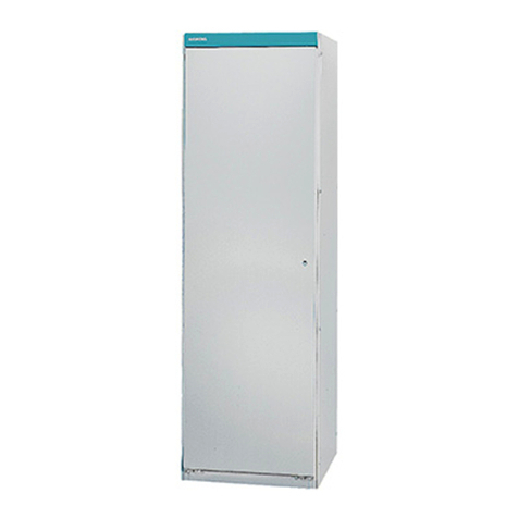
The EB-32, EB-33 and EB-35 Enclosures (See Figure
1) from Siemens Industry, Inc. are designed to accom-
modate System 3 control panels, input and output
modules, and all power supplies utilized in the system.
They can be either surface or semi-flush mounted.
Each enclosure consists of a back box and door cover
assembly fabricated of heavy gauge sheet steel. The
back box, which is finished in a black enamel, is
designed for mounting the "Z" brackets and "U"
channel supports on which are mounted the controls,
modules, and power supplies.
INSTALLATION
Securely fasten the control panel enclosure to a shock
and vibration-free surface in a clean, dry area. It
should be mounted with the top of the enclosure
approximately 6 feet above the floor. The location
should ensure that the control panel is easily visible
and readily accessible for maintenance. Leave
sufficient room to open the enclosure door.
Wiring should be in accordance with national and local
codes for fire alarm circuits. For AC supply power, use
No. 14 or larger AWG, 600V insulation wire.
1. Remove knockouts in the backbox where field
wiring is required. (Refer to Table 1, Table 2 and
Figure 1.)
2. Hold the empty enclosure against the wall at the
designated height.
3. Mark drill points on the wall in the center of the
two slots on the upper rear of the box (Refer to
Figure 1).
4. Drill the two holes and screw in the top bolts,
leaving a small gap between the wall and each
top bolt.
5. Mount the enclosure on the two bolts and then
install the bottom bolts.
6. Tighten all bolts securely against the back wall of
the enclosure.
7. Pick up the module/frame assembly by the straps
provided at the end of the wiring channels. Do not
place hands behind the modules, as the circuitry
may be damaged.
8. Install the module/frame assembly in the enclo-
sure, securing it to the studs with the 5/16 inch
nuts provided.
CAUTION: Do not overtighten nuts (do not use
ratchet type wrench), as the studs can be
broken if excessive force is applied.
WIRING
In compliance with UL-864, all power limited fire
protective signaling conductors must be separated a
minimum of ¼ inch from all of the following items
located within a control panel:
• electric light
• power
• Class 1 or non-power limited signaling conductors
To meet these requirements, the following guidelines
must be observed when installing modules and
wiring to a System 3 control panel.
When installing power limited field wiring, the installer
must comply with NEC article 760-54, which states:
The fire alarm power-limited circuits are installed
using Types FPL, FPLR, FPLP or permitted
substitute cable, provided these power-limited
cable conductors extending beyond the jacket are
separated by a minimum of 0.25 in. (6.35 mm) or
by a nonconductive sleeve or nonconductive
barrier from all other conductors.
P/N 315-093680-9
Siemens Industry, Inc.
Building Technologies Division
Florham Park, NJ
Siemens Canada Limited
Building Technologies Division
2 Kenview Boulevard
Brampton, Ontario L6T 5E4 Canada
2
NOTE: If power limited wiring is not used within a
System 3 enclosure, the following guidelines
do not apply. In that case, be sure to follow
standard wiring practices.
WIRING ENTERING THE ENCLOSURE
Non-power Limited Wiring
Wiring to the System 3 module terminations shown in
Table 1 is considered non-power limited and must
enter through the knockouts in the top right side of the
enclosure (See Figure 2). Wiring between the knock-
outs specified and the module termination must be in
the shortest route, and must not overlap any other
wiring.
1ELBAT
ELUDOMNOITANIMRET
U03-AA
U03-EA
73-CB
53-PC
53-PC
23-MP
53-SP
S53-SP
022/53-SP
U03-CR
U03-MR
03-MS
03-RS
23-RS
53-RS
U03-CT
R-IRT
8,7,4,3noitisoP1BT
4,3noitisoP1BT
snoitisoPllA
12-31noitisoPBT
83,73,53-23noitisoPBT
snoitisoPllA
6-4,2,1noitisoP
1BT
6-4,2,1noitisoP1BT
6-4,2,1noitisoP1BT
snoitisoPllA
snoitisoPllA
snoitisoPllA
snoitisoPllA
,21-01,8-6,4-2
noitisoPBT
34-14,93-73,53-33,13-41
snoitisoPllA
snoitisoPllA
8-6noitisoPBT
WIRING IN THE ENCLOSURE
Non-power Limited Wiring
Wiring from the batteries to the BC-37 is considered
non-power limited. To maintain the required separa-
tion, the wiring must be routed in the right side of the
enclosure.
All wiring within the enclosure must be routed as
shown in Figure 2. To maintain the required ¼inch
minimum spacing, tie-wrap the wiring to the
module mounting screws.
WIRING ENTERING THE ENCLOSURE
Power Limited Wiring
Wiring to the System 3 module terminations shown in
Table 2 is considered power limited and must enter
through the knockouts in the top left side of the
enclosure (See Figure 2).
2ELBAT
ELUDOMNOITANIMRET
53-IB
53-PC
U03-LT
D-IRT
R-IRT
S-IRT
U13-NZ
SU/AU43-NZ
SD53/ST53/53-UZ
01-4noitisoPBT
21-
1noitisoPBT
snoitisoPllA
7-1noitisoPBT
5-1noitisoPBT
5-1noitisoPBT
6-1noitisoPBT
21-1noitisoPBT
21-1noitisoP
BT
WIRING LEAVING THE ENCLOSURE
Power Limited Wiring
Where power limited wiring is desired for audible
circuits, use the model PLM-35. Refer to the PLM-35
Installation Instructions, P/N 315-093495, for informa-
tion on installation of the module and wiring to the
audible circuits.
3
Figure 1
System 3 Enclosure Mounting Dimensions
Enclosure A B C D
EB-32 201/2in (52.07 cm) 223/8in (56.83 cm) 241/2in (62.23 cm)
EB-33 31 in (78.74 cm) 327/8in (83.50 cm) 35 in (88.95 cm) 151/2in (39.37 cm)
EB-35 52 in (132.08 cm) 53 7/8in (136.84 cm) 56 in (142.24 cm) 26 in (66.04 cm)
POWER LIMITED
POWER LIMITED
NON-
POWER
LIMITED
P = POWER LIMITED N = NON-POWER LIMITED
NON-POWER LIMITED
AC
MAIN
BATTERY
INPUT
TB1
TB1
+-
CP-35
PS-35
ZU-35TS BC-37
AE-30U
SR-32
AE-30U AA-30U
AA-30U
TRI-R
TRI-S
TRI-R
TRI-D
PLM-35PLM-35
ZU-35DSZU-35ZN-31UZN-34U2
1
2
3
4
5
8
7
6
1
2
3
4
5
8
7
6
1
2
3
4
5
8
7
6
1
2
3
4
5
8
7
6
Figure 2
System 3 Power Limited Wiring
P/N 315-093680-9
Siemens Industry, Inc.
Building Technologies Division
Florham Park, NJ
Siemens Canada Limited
Building Technologies Division
2 Kenview Boulevard
Brampton, Ontario L6T 5E4 Canada

This manual suits for next models

2

Other Siemens Enclosure manuals

Siemens H200 User manual

Siemens

Siemens H200 User manual

Siemens CAB2-BD/-RD User manual

Siemens

Siemens CAB2-BD/-RD User manual

Siemens Simatic 6DL2804-0 Series User manual

Siemens

Siemens Simatic 6DL2804-0 Series User manual

Siemens TH 180 AP User manual

Siemens

Siemens TH 180 AP User manual

Siemens 8MF2000 User manual

Siemens

Siemens 8MF2000 User manual

Siemens SIRIUS 3SB380D Series User manual

Siemens

Siemens SIRIUS 3SB380D Series User manual

Siemens 549-521 User manual

Siemens

Siemens 549-521 User manual

Siemens MTE-2 User manual

Siemens

Siemens MTE-2 User manual

Siemens 7KE6020-1AA00 User manual

Siemens

Siemens 7KE6020-1AA00 User manual

Siemens CAB1-X User manual

Siemens

Siemens CAB1-X User manual

Siemens BZLLRHSE User manual

Siemens

Siemens BZLLRHSE User manual

Siemens EAD-3 User manual

Siemens

Siemens EAD-3 User manual

Siemens SENTRON VL 3VL93008BD00 User manual

Siemens

Siemens SENTRON VL 3VL93008BD00 User manual

Siemens Milltronics HydroRanger 200 User manual

Siemens

Siemens Milltronics HydroRanger 200 User manual

Siemens FDMH292-R User manual

Siemens

Siemens FDMH292-R User manual

Siemens SINAMICS G120P User manual

Siemens

Siemens SINAMICS G120P User manual

Siemens BB-55 User manual

Siemens

Siemens BB-55 User manual

Siemens FHD2012-U1 User manual

Siemens

Siemens FHD2012-U1 User manual

Siemens FS-250-ENCL/-R User manual

Siemens

Siemens FS-250-ENCL/-R User manual

Siemens CERBERUS PYROTRONICS ALI-8 User manual

Siemens

Siemens CERBERUS PYROTRONICS ALI-8 User manual

Siemens FHA2040-A1 User manual

Siemens

Siemens FHA2040-A1 User manual

Siemens SIRIUS ACT 3SU180-N Series User manual

Siemens

Siemens SIRIUS ACT 3SU180-N Series User manual

Siemens 8MF4900 User manual

Siemens

Siemens 8MF4900 User manual

Siemens MLE-6 User manual

Siemens

Siemens MLE-6 User manual

Popular Enclosure manuals by other brands

StarTech.com HSB1SATSASVA quick start guide

StarTech.com

StarTech.com HSB1SATSASVA quick start guide

OBERON 1026 Series installation guide

OBERON

OBERON 1026 Series installation guide

L-Acoustics L-CASE II owner's manual

L-Acoustics

L-Acoustics L-CASE II owner's manual

Pulsar AWO-270 user manual

Pulsar

Pulsar AWO-270 user manual

Outline SCALA 90 user manual

Outline

Outline SCALA 90 user manual

MTX ThunderForm HONDA CIVIC user manual

MTX

MTX ThunderForm HONDA CIVIC user manual

ZALMAN HD135 user manual

ZALMAN

ZALMAN HD135 user manual

Supero SC743TQ-865 user manual

Supero

Supero SC743TQ-865 user manual

Kohler 301 installation guide

Kohler

Kohler 301 installation guide

Hubbell GAI-TRONICS 733-006 manual

Hubbell

Hubbell GAI-TRONICS 733-006 manual

GAMDIAS Talos-E3 Quick installation guide

GAMDIAS

GAMDIAS Talos-E3 Quick installation guide

Salsbury Industries S-61000 Series installation instructions

Salsbury Industries

Salsbury Industries S-61000 Series installation instructions

Caselabs magnum tx10 Assembly manual

Caselabs

Caselabs magnum tx10 Assembly manual

BlueStork BS-EHD-35/COMBO/30 user manual

BlueStork

BlueStork BS-EHD-35/COMBO/30 user manual

Electro-Voice Marquis KD9 Instruction booklet

Electro-Voice

Electro-Voice Marquis KD9 Instruction booklet

Rittal HD 1302.600 Assembly and operating instructions

Rittal

Rittal HD 1302.600 Assembly and operating instructions

Thermaltake GTS VO3000 Series user manual

Thermaltake

Thermaltake GTS VO3000 Series user manual

Antec P190 user manual

Antec

Antec P190 user manual

manuals.online logo
manuals.online logoBrands
  • About & Mission
  • Contact us
  • Privacy Policy
  • Terms and Conditions

Copyright 2025 Manuals.Online. All Rights Reserved.