Siemens RAJA+ Operating instructions

Installation, Maintenance
& Troubleshooting Guide
For RAJA
+
Agriculture Starters
& Controllers

Contents:
3. Direct On Line Controller:
3.1 Product description
3.2 Wiring diagram
3.3 Technical Details
3.4 Installation
3.5 Operating procedure in normal condition
3.6 Troubleshooting guidelines in case any incoming fault is
present before switching ON the motor
3.7 Troubleshooting guidelines in fault condition when motor stops
while it is in running condition
3.8 Troubleshooting guidelines in case any fault is at the load side

Installation, Maintenance & Troubleshooting guide | Version 03
Product: Direct On
Line Controller
3.1: Product description
3
3
1
2
5
7
12
13
4
11
6
8
9
10
1. ‘ON’ push button (green)
2. ‘OFF/RESET’ push button (red)
3. Door knob
4. Metal Enclosure
5. Door
6. Mechanical Latch (OFF push button) to be used for preventing undesired ON operation of Starter
7. Name plate
8. LED (amber) to indicate availability and healthiness of incoming power supply
9. Green LED to indicate Motor ON status
10. Rocker switch (Control ON/OFF)
11. Dual VA meter (For indication)
12. Phase Selector switch
13. Earthing screw

Installation, Maintenance & Troubleshooting guide | Version 03
4
Inside view of Direct On Line Controller
Fig.8
1: Amber LED
2: Green LED
3: Rocker Switch
4: Contactor
5: ON push button
6: OFF push button
7: Thermal Overload Relay
8: Terminal Block TB1
9: Terminal Block TB2
10: Earthing Screw
11: AV meter
12: Line monitoring relay
13: Starter Operating Modes
14: Phase selector switch
1
2
5
6
4
7
8
9
121314
10
3
11

3.2: Wiring Diagram: DOL Controller
5
Installation, Maintenance & Troubleshooting guide | Version 03

6
3.21 Control logic diagram
Installation, Maintenance & Troubleshooting guide | Version 03

7
3.22 Power circuit diagram
Installation, Maintenance & Troubleshooting guide | Version 03

8
Table: 15 Technical details of DOL Controller
Note: xx: Coil voltage; Z6:200-400V AC; Z8: 260-460V AC
yy: Coil voltage; FE:200-400V AC; FF: 260-460V AC
*Type 1 coordination as per IS/IEC 60947-4-1 Standard.
3.3: Technical details
Type (HP /
kW)
Ie
(A) Contactor
Relay
Range
(A)
Line
Monitoring
Relay
Recommended
Max. Back-up
HRC Fuse rating,
SIEMENS Make
type 3NA7
– 500V*
Max.
Recommended
Cu cable size
(sq:mm)
3TE7121-1HC14-1Axx 3 / 2.2 6.5 3TS3010-0Axx-08K 3US5000-1H8K 5-8 7UG0613-0yy20 20A/500V 1.5
3TE7121-1KC16-1Axx 5 / 3.7 10 3TS3110-0Axx-08K 3UW5102-1K 8-12.5 7UG0613-0yy20 25A/500V 1.5
3TE7121-2AC17-1Axx 6 / 4.5 12 3TS3210-0Axx-08K 3UW5102-2A 10-16 7UG0613-0yy20 25A/500V 1.5
3TE7121-2BC18-1Axx 7.5 / 5.5 14.5 3TS3210-0Axx-08K 3UW5102-2B 12.5-20 7UG0613-0yy20 25A/500V 2.5
3TE7121-2CC21-1Axx 10 / 7.5 19.5 3TS3311-0Axx-08K 3UW5202-2C 16-25 7UG0613-0yy20 32A/500V 2.5
Installation, Maintenance & Troubleshooting guide | Version 03

9
3.4: Installation
• Open the door by rotating the door lock anticlockwise.
• Mount the starter on a vertical wall/ plate free from vibrations with proper nuts and bolts.
Refer operating instruction for mounting dimensions.
• Remove the rubber grommets for the incoming and outgoing cable connections. (Refer Fig. 8)
• Connect incoming and outgoing cables as follows (Refer Fig. 8):
- Use proper cable glands to ensure dust proofing. For conduit entry use packed washers.
- Select correct size of cables from Table 15
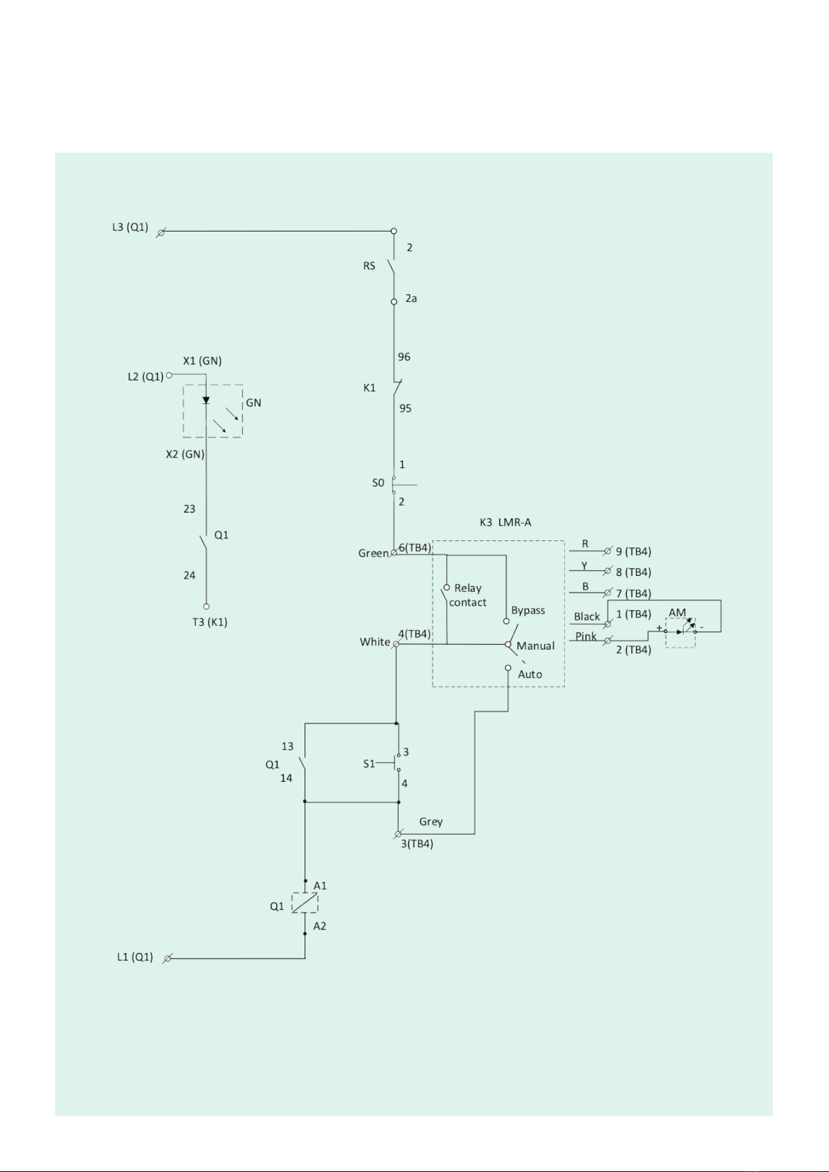
- Connect line and motor leads exactly as per wiring diagram pasted inside the cover of the starter.
- Terminate the incoming supply cables on terminal block TB1 & outgoing cables to motor on terminal block
TB2,(Tightening torque -Refer table 15B)
NOTE: LMRA is set in Manual mode (Factory setting)
- Connect the earthing conductor to terminals marked (earth) on the starter body with torque 1.2 to 1.6Nm.
The Starter is now ready for commissioning.
Commissioning :
Installation, Maintenance & Troubleshooting guide | Version 03
Operating Characteristics:
The given characteristics (Fig. 6) are average values of all ranges and sizes of bimetal relays and are mainly intended to indicate
the inverse time current characteristics & tripping times of the same. The tripping times shown are for relays starting from the cold
state. At operating temperatures (heated at rated current) these are reduced to about 25% of the value obtained from the
characteristics.
Caution
• During commissioning or maintenance always ensure that the main supply is disconnected by switching
off the main switch & Rocker switch.
• If the relay trips even when set at rated motor current the suitability of the starter/relay for the particular application
should be checked with the nearest Siemens office.
For exact setting of overload relay, follow the instruction given below:
Before switching ON recheck all external connections.
• Overload relay setting:
- For closer protection set the overload relay to actual phase current as measured by an ammeter. In the absence
of an ammeter, use the procedure given below:
- Start the motor and let it run for 30 mins. Then gradually reduce the relay settings till it trips. Set the relay at a
slightly higher value than this setting. Overload relay characteristics shown in Fig. 6 can be used to estimate the
average tripping time at different multiples of set current.
- Allow a reset time of approx. 4 min. before pressing the blue knob on the relay to reset it.
- Restart the motor after some time. If the relay does not trip then consider it to be properly set. If the relay trips,
set at a little higher value than before and recheck.
• Close the front door.

Table: 15A Mounting torque values
Sr. No Location Size Torque
1 Earthing screw (cover to body) M5 2.5-3.0Nm
2 Contactor 3TS30..33 M4 0.8-1.4Nm
3 LMR-A M4 0.8-1.4Nm
4 Terminal block 30A M4 0.8-1.4Nm
5 ON& OFF /Rest link ST4.2x9.5 0.8-1.2Nm
6 Dual VA Meter M4 0.2-0.3Nm
7 Selector Switch 3LD4 M4 0.8-1.1Nm
Table: 15B Terminal torque values
Operation:
• Ensure the door is closed.
• Rotate the Latch away from OFF push button
• Switch On the rocker switch.
• Check the status of amber LED. Wait till amber LED is continuously ON then only proceed.
• Depending upon Selector switch knob position for phase selection, Indication of incoming power
supply voltage can be seen on Dual VA meter.
• For starting the motor, press Green push button marked ‘I’ (Fig. 7)
• Line current of R phase is indicated by Dual VA meter.
• Indication of Motor ON can be seen on starter door through green LED.
• For stopping the motor press Red push button marked ‘O’ (Fig. 7)
Reset Operation
– If the overload relay trips, Reset manually.
(Allow a reset time of approx. 4 min.)
10
Installation, Maintenance & Troubleshooting guide | Version 03
Sr. No Type Size Torque
1 3TS30..32 M4 0.8-1.4Nm
2 3TS33 M4 1.0-1.5Nm
3 Terminal block 30A M4 0.8-1.4Nm
4 Contact block 3SB5 M3.5 0.8-1.2Nm
5 Coil Terminals A1/A2 M3.5 0.8-1.2Nm
6 Aux. terminals of all Relays M3.5 0.8-1.2Nm
7 3UW51/52,3US50 M4 1.0-1.5Nm
8 3TX4010-2A M4 0.8-1.1Nm
9 Indicating light – Amber/Green M3 0.8Nm
10 Dual VA Meter – Current terminals M4 1.2Nm
11 Dual VA Meter – Voltage terminals M4 1.2Nm
12 3TS30..32 M4 0.8-1.4Nm

1011
LMR-A: Manual mode
7A : Keep the LMR-A in Manual mode.
7B : Switch ON 3-Phase incoming main supply.
7C : Turn ON the rocker switch
7D : Amber LED will start blinking for a period of min 0.5 min.
7E : 0.5 min is the default setting which can vary from min 0.5 min to max.5min.
7F : After the ON-delay duration, amber LED will ON continously indicating that the incoming supply is Healthy
(Assuming incoming supply is healthy).
7G : Press the green push putton for switching ON the starter.
7H : Starter gets switched ON
7I : Green LED turns ON indicating that the starter is ON.
7J : Starter switches OFF automatically after water tank level reach P3 sensor level.
7K : Green LED turns OFF indicating that the starter is OFF.
7L : Amber LED indication remains continous ON.
7M : Switch OFF the 3-phase incoming main supply.
7N : Amber LED indication gets turned OFF indicating that there is no incoming main supply.
3.5: Operating procedure in normal condition
Starter operation:
Table: 11 FASD starter operating sequence in normal condition
LMR-A
Mode
Manual
Auto
Bypass
7A
3ф main
supply
ON
ON
ON
7B
Rocker
switch
ON
ON
ON
7C
Amber
LED
Blink
(On-delay
duration)
Blink
(On-delay
duration)
Blink
(On-delay
duration)
7D
LMR-A
On-Delay
0.5-5min
0.5-5min
0.5-5min
7E
Amber
LED
ON
ON
ON
ON
ON
ON
ON
ON
ON
7F
‘ON’ Push
button
ON
NA
ON
7G
Starter
Operation
7H
Starter
Operation
7I
ON operation
Starter
Operation
OFF
OFF
OFF
7J
OFF
OFF
OFF
Green
LED
7K
OFF
OFF
OFF
3ф main
supply
7M
Amber
LED
7L
ON
ON
ON
OFF
OFF
OFF
Amber LED
indication
7N
OFF operation
Installation, Maintenance & Troubleshooting guide | Version 03

LMR-A: Auto mode
7A : Keep the LMR-A in Auto mode.
7B : Switch ON the 3-Phase incoming main supply.
7C : Turn ON the rocker switch.
7D : Amber LED will start blinking for a period of min 0.5 min.
7E : 0.5 min is the default setting which can vary from min 0.5 min to max.5min.
7F : After the ON-delay duration, amber LED will ON continously indicating that the incoming supply is
healthy(Assuming incoming supply is healthy).
7G : Not applicable (No need to press ON push button)
7H : Starter gets switched ON automatically.
7I : Green LED turns ON indicating that the starter is ON.
7J : Starter switches OFF automatically after the above step ‘1K‘
7K : Green LED turns OFF indicating that the starter is OFF.
7L : Amber LED indication remains continous ON.
7M : Switch OFF the 3-phase incoming main supply.
7N : Amber LED indication gets turned OFF indicating that there is no incoming main supply.
LMR-A: Bypass mode
7A : Keep the LMR-A in Bypass mode.
7B : Switch ON the 3-Phase incoming main supply.
(*Customer may switch ON the starter directly after switching ON the 3 phase incoming supply irresepctive of Blinking
status as there is only indication for incoming supply faults and no Protection in Bypass mode).
7C : Turn ON the rocker switch.
7D : Amber LED will start blinking for a period of min 0.5 min.
7E : 0.5 min is the default setting which can vary from min 0.5 min to max.5min.
7F : After the ON-delay duration, amber LED will ON continously indicating that the incoming supply is healthy
(Assuming incoming supply is healthy).
7G : Press the green push putton for switching ON the starter.
7H : Starter gets switched ON.
7I : Green LED turns ON indicating that the starter is ON.
7J : Starter switches OFF automatically after delivery tank water level reach P3 sensor level.
7K : Green LED turns OFF indicating that the starter is OFF.
7L : Amber LED indication remains continous ON.
7M : Switch OFF the 3-phase incoming main supply.
7N : Amber LED indication gets turned OFF indicating that there is no incoming main supply.
Installation, Maintenance & Troubleshooting guide | Version 03
12

13
#: Phase loss1, Phase reversal2, Under voltage3, Over voltage4, Phase unbalance5
NA – Starter is unprotected from incoming power supply faults,only protection from load side faults. In this mode, amber LED
will continously ON if incoming power supply is healthy and will blink if the incoming power supply is unhealthy– Refer 3.8
1) LMR-A: Manual mode
8A : Check the mode of LMR-A, if it is manual mode.
8B : Switches ON the 3-Phase incoming main supply.
8C : Switch ON the rocker switch
8D : Amber LED will start blinking
8E : Amber LED will blink for a duration of min.30sec.
8F : After the ON delay duration, amber LED remains blinking indicating that the 3phase incoming supply is unhealthy.
18G : - Check the rated operational voltage of the starter in incoming terminal block (TB1) between L1- L2 , L2-L3, L1-L3
with suitable equipment e.g. multimeter.
- Check for the phase loss in any phase (L1,L2,L3) with suitable equipment e.g. multimeter.
18H : - After resuming incoming main supply to normal condition,
- Repeat the steps from 8A to 8F and then go to step no.8I
If fault still exists, then
28G : - Check the phase sequence of all the phases of incoming main supply.
- Identify the wrong sequence of phase connected in any of the incoming terminal.
28H : - Connect the phase sequence of all the phases correctly (R phase to L1 , Y phase to L2, B phase
to L3) to the incoming main supply terminals of Terminal block TB1.
- Repeat the steps from 8A to 8F and then go to step no.8I
3.6: Troubleshooting Guidelines in case any incoming
supply fault is present before switching ON the Starter
Starter Fault conditon:
Table: 17 DOL Controller operating sequence in fault condition
8A 8B 8C 8D 8E 8F 8G 8H 8L8J 8K8I
Installation, Maintenance & Troubleshooting guide | Version 03
Manual
Auto
Bypass
3ф
main
supply
ON
ON
ON
Rocker
switch
ON
ON
ON*
LMR-A
On-Delay
0.5-5min
0.5-5min
0.5-5min
Amber
LED
Blink
(On-delay
duration)
Blink
(On-delay
duration)
Blink
(On-delay
duration)
Amber
LED
Blink
Blink
Blink
#
#
NA
Possible
causes
of fault
1)
2)
NA
ON
ONONON
ON
Corrective
action
Amber
LED
‘ON’ Push
button
Starter
Operation
ONON
NA
ON
ON
ONON
Green
LED
LMR-A
Mode
ON operation

14
If fault still exists, then
38G : - Check the rated operational voltage of the starter in incoming terminal block (TB1) between L1-L2, L2-L3, L1-L3
with suitable equipment e.g. multimeter.
- Check whether the 3-phase voltage in the incoming terminals of terminal block TB1 is <minimum required voltage
(Refer table no.18).
38H : - Keep the 3-phase voltage to the incoming terminals of terminal block TB1 to a voltage between min.required voltage
& Max.voltage allowed (Refer table no.18).
- Repeat the steps from 8A to 8F and then go to step no.8I
If fault still exists, then
48G : - Check the rated operational voltage of the starter in incoming terminal block (TB1) between L1-L2, L2-L3, L1-L3
with suitable equipment e.g. multimeter.
- Check whether the 3-phase voltage in the incoming terminals of terminal block TB1 is >Maximum voltage allowed.
(Refer table no.18).
48H : - Keep the 3-phase voltage to the incoming terminals of terminal block TB1 to a voltage between min.required voltage
& Max.voltage allowed (Refer table no.18).
- Repeat the steps from 8A to 8F and then go to step no.8I
If fault still exists, then
58G : - Check the rated operational voltage of the starter in incoming terminal block (TB1) between L1-L2, L2-L3, L1-L3.
- Check whether the operational line voltage difference between any 2 phase in the incoming. terminals of terminal
block TB1 is >50V.
58H : - Starter will be operational only if the incoming supply voltage difference between any 2 phase in the incoming terminal
block TB1 of the starter is <=50V.
- Repeat the steps from 8A to 8F and then go to step no.8I
8I : Amber LED will remain ON continously indicating that the fault is cleared
8J : Press the Green ON push button to switch ON the starter.
8K : Starter gets switched ON.
8L : Green LED turns ON indicating that the starter is ON.
Installation, Maintenance & Troubleshooting guide | Version 03
2) LMR-A: Auto mode
8A : Check the mode of LMR-A, if it is Auto mode.
8B to 8I : Follow steps from 8B to 8I of LMR-A Manual mode.(Corrective action 1)
8J : No need to press ON push button.
8K : Starter switches ON automatically.
8L : Green LED turns ON indicating that the starter is ON.
* LMR-A: Bypass mode
As in Bypass mode there is no protection from the incoming supply faults, however there may be some conditions, example
mentioned below where Starter may not ON –
1. Phase loss
2. Incoming supply voltage less than the minimum required operational voltage of the Starter.
3. Incoming supply voltage is very high etc.......
In the above conditions check the Starters as explained in Auto & Manual Mode.
Manual
195
250
205
260
400
455
390
445
(Z6) 200-400
(Z8) 260-460
Table: 18 Range of Under voltage & Over voltage
Starter
Voltage Range
(V)
Undervoltage fault
Trip voltage for
undervoltage fault
(V)
Healthy voltage
(V)
Trip voltage for
Overvoltage fault
(V)
Healthy voltage
(V)
Overvoltage fault

15
3.7: Troubleshooting Guidelines in fault condition when
motor stops while it is in running condition
Table: 19 DOL Controller operating sequence in fault condition
1) LMR-A: Manual mode
9A : Motor suddenly stops after running for some time.
9B : Check the mode of LMR-A, if it is Manual mode.
9C : Amber LED will start blinking
9D to 9I : Follow steps from 8G to 8L of Table 17 LMR-A manual mode (Corrective action 1)
9J : Motor starts running again.
2) LMR-A: Auto mode
9A : Motor suddenly stops after running for some time.
9B : Check the mode of LMR-A, if it is Auto mode.
9C : Amber LED will start blinking
9D to 9I : Follow steps from 8G to 8L of Table 17 LMR-A Auto mode (Corrective action 2)
9J : Motor starts running again.
Starter Fault conditon:
3) LMR-A: Bypass mode
As in Bypass mode there is no protection from the incoming supply faults, however there may be some conditions, example
mentioned below where Starter may not ON –
1. Phase loss
2. Incoming supply voltage less than the minimum required operational voltage of the Starter.
3. Incoming supply voltage is very high
etc.......
In the above conditions check the Starters as explained in Auto & Manual Mode.
Motor
conditon
Not
Running
Not
Running
Not
Running
Installation, Maintenance & Troubleshooting guide | Version 03
LMR-A
Mode
Manual
Auto
Bypass
Motor
conditon
Running
Running
Running
Amber
LED
Blink
Blink
Blink
Possible
causes
of fault
#
#
NA
Corrective
action
1)
2)
NA
ON
ON
Amber
LED
ON
ON
ON
Starter
operation
ON
Green
LED
ON
ON
ON
9A 9B 9J9C 9D 9E 9F 9H 9I9G
ON
NA
ON
‘ON’
Push
button
#: Phase loss1, Phase reversal2, Under voltage3, Over voltage4, Phase unbalance5
NA – Starter is unprotected from incoming power supply faults,only protection from load side faults. In this mode, amber LED
will continously ON if incoming power supply is healthy and will blink if the incoming power supply is unhealthy– Refer 3.8
ON operation

16
3.8: Troubleshooting Guidelines in case
any fault is at load side
Thermal overload relay provide protection from:
a) overload condition at Motor
b) single phasing at load side
a) overload condition at Motor: check the suitable Motor current rating and adjust the overload relay setting
dial as per the requirement.
b) Single phasing at load side – Overload relay tripped as inbuilt feature to protect from single phase faults.
Check the single phasing condition at Motor side terminal TB2,TB3 to Motor.
For both conditions restart the Starter after proper reset time of approx. 4 min.
Steps to be followed
Installation, Maintenance & Troubleshooting guide | Version 03

Article no. SI EP CC RajaSM3 042021
Published by
Siemens Ltd
Smart Infrastructure
Electrical Products
R&D Building, 48,
Thane-Belapur Road
Thane 400708, India
Smart Infrastructure intelligently connects energy systems,
buildings and industries, enhancing the way we live and
work to significantly improve efficiency and sustainability.
We work together with customers and partners to create
an ecosystem that both intuitively responds to the needs of
people and helps customers achieve their business goals.
It helps our customers to thrive, communities to progress
and supports sustainable development to protect our planet
for the next generation.
Creating environments that care.
siemens.com/smart-infrastructure
Subject to changes and errors. The information given in this document only contains
general descriptions and/or performance features which may not always specifically
reflect those described, or which may undergo modification in the course of further
development of the products. The requested performance features are binding only
when they are expressly agreed upon in the concluded contract.
Other manuals for RAJA+
2
Table of contents