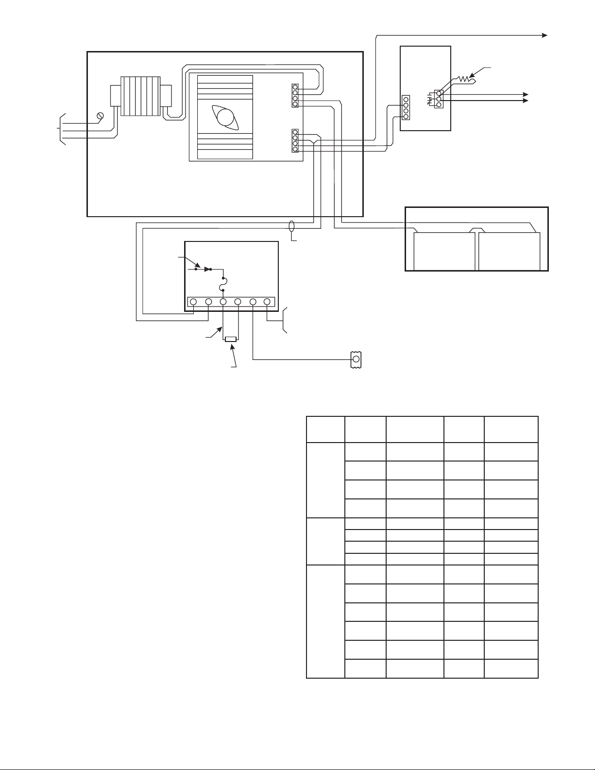
manuals.online logo
Brands
  1. Home
  2. •
  3. Brands
  4. •
  5. Siemens
  6. •
  7. Firefighting Equipment
  8. •
  9. Siemens RM-30U User manual

Siemens RM-30U User manual

Wiring Instructions
Models RM-30U/RM-30RU
Release Modules
Fire Safety
P/N 315-085100-10
Siemens Building Technologies, Inc.
8 Fernwood oad
Florham Park, New Jersey 07932
Siemens Building Technologies, Ltd.
2 Kenview Boulevard
Brampton, Ontario L6T 5E4 CN
RM-30U
CP-35
CP-35
6
42
38
37
5
4
3
2
1
+
_
DISCONNECT
SWITCH S1
(SEE NOTE 4)
INPUT POWER
(SEE NOTE 1)
3 OHMS MAX
TOTAL LINE RESISTANCE OF
DISCHARGE DEVICE CIRCUIT
CONNECTING WIRES
OPERATING SOLENOID
OR OTHER APPROVED LOAD
(SEE NOTE 1 AND TABLE 1)
CLASS B CONNECTED RELEASING DEVICE CIRCUIT
POLARITY SHOWN IN SUPERVISORY CONDITION
SUPV: 1.0 VDC, 5mA
ACTIVATED: 24 VDC, 1.5mA MAX
ALARM ACTIVATED INPUT
24 VDC, 21mA FROM CP-35
(AS SHOWN) OR EQUIVALENT
ACTUATION INPUT
24 VDC, 3mA FROM
CP-35, TERMINAL 42,
ZU-35, TERMINAL 1 OR 7,
OR TL-30U, TERMINAL 3
THIS CONNECTION MUST
BE MADE TO PROVIDE
ACTUATION POWER
DURING ALARM ONLY
3A FUSE
RM-30RU
CP-35
CP-35
6
42
38
37
5
4
3
2
1
+
_
DISCONNECT
SWITCH S1
(SEE NOTE 4)
JUMPERS
(3 PLACES--
SEE TABLE 1)
INPUT POWER
(SEE NOTE 1)
3 OHMS MAX
TOTAL LINE RESISTANCE OF
DISCHARGE DEVICE CIRCUIT
CONNECTING WIRES
SERIES CONNECTED OPERATED
SOLENOID(S) RATED 6 VDC EACH
OR OTHER APPROVED LOAD
(SEE NOTES 1 AND 2)
ALARM ACTIVATED INPUT
24 VDC, 21mA FROM CP-35
(AS SHOWN) OR EQUIVALENT
ACTUATION INPUT
24 VDC, 3mA FROM
CP-35, TERMINAL 42,
ZU-35, TERMINAL 1 OR 7,
OR TL-30U, TERMINAL 3
THIS CONNECTION MUST
BE MADE TO PROVIDE
ACTUATION POWER
DURING ALARM ONLY
3A FUSE
LOAD
ADJUST
JUMPERS
NOTES for RM-30RU:
1. Operating solenoids, relay, or other approved loads
operate from a 24 VDC source. Use Battery ransfer
Modules BC-35 or DC Program Plug JP-D in P2 of the
CP-35.
2. he RM-30RU Releasing Device Module may be used
to activate up to four 6 VDC solenoids. able 1
describes the only acceptable combinations of
solenoids and/or resistors. Any other combination not
described in able 1 is not permitted.
3. A manual control for halon release must be utilized to
satisfy UL/FM requirements. he control may be
accomplished by connecting a manual station to the
ZU-35 with output terminal 1 or 7 connected to the
actuation input (terminal 6) of the RM-30U or RM-30RU.
4. Placing the disconnect switch in the disconnect position
removes the power to the operating loads and causes
an associated trouble condition of that module.
FM Approval
Refer to the System 3 Pre-Action Sprinkler Control Diagram
(P/N 315-091776) for an FM approved configuration.
NOTE: HE RELEASING DEVICE MUS BE AN FM
APPROVED ELEC RIC SOLENOID VALVE FOR
AN AU OMA IC WA ER CON ROL VALVE
RELEASE.
1ELBAT
noitacilppA
snemeiS
ledoM
rodneV
rebmuNtraP
forebmuN
niseciveD
seireS
forebmuN
srotsiseR
seireSni
forebmuN
srepmuJ
tuot
1002APFN
)002-MF(
6-CEYPCOCSA
6-235812VH
CDV6enO33
6-CEYPCOCSA
6-235812VH
CDV6owT22
6-CEYPCOCSA
6-235812VH
CDV6eerhT11
6-CEYPCOCSA
*6-235812VH
CDV6ruoF00
21-CEYPCETITPANS
**5F4A-N2-A3282
CDV21owT00
42-CEYPCETITPANS
6F2A-60X-A3282
CDV42enO00
.desuebtsumsdionelosV6detcennocseiresruoF*
sdionelosCDV6ehtfonoitanibmocynahtiwdionelosCDV21enoximotdettimreptonsitI**
.srotsiserro/dna
NOTES for RM-30U:
1. For NFPA 13 Automatic Water Control Valve Release,
use an electric solenoid valve. See able 2. One valve
max per circuit.
2. For NFPA 12A Halon Releasing Service, use only an
electric solenoid valve from able 2. One valve max
per circuit.
3. For NFPA 2001 Releasing Service, use only an
approved electric actuator. See able 2.
4. Placing the disconnect switch in the disconnect
position has the following effect:
 removes power to the operating loads
 causes a trouble condition associated with that module
5. A manual control for Halon release must be used to
satisfy UL and FM requirements. o make this control,
connect a manual station to the ZU-35, with output
terminal 1 or 7 connected to RM-30U actuation input
terminal 6.
6. Solenoid supervised for open only.
P/N 315-085100-10
24 VAC
BATTERY +
_
+
_
+
_
DC OUT
FAULT
SUPERVISED BY ZN-34U2
TO ZN-34U2 FOR POWER
SUPPLY SUPERVISION
MOUNT RPR-1 IN
ALARM-SAF CABINET
CHASSIS
CHASSIS
120 VAC
INPUT NEUTRAL
HOT
RPR-1
RM-30U
6
42
5
4
3
2
1
+
++
_
__
+
+
_
_
O
TB2
TB1
A
C
CONNECT TO PS-35, TB1-6
END OF LINE
RESISTOR
3.6K, 1/4W
P/N 140-820185
DISCONNECT
SWITCH S1
(SEE NOTE 4)
MUST BE WITHIN 20 FEET
OF RIGID CONDUIT
BETWEEN PANELS
3 OHMS MAX TOTAL LINE RESISTANCE
OF DISCHARGE DEVICE CIRCUIT
CONNECTING WIRES, SEE NOTE 6
OPERATING SOLENOID OR OTHER
APPROVED LOAD (SEE NOTES 1, 2, AND 3)
CLASS B CONNECTED RELEASING DEVICE CIRCUIT
POLARITY SHOWN IN SUPERVISORY CONDITION
FOR NFPA 13 AND NFPA 2001
ALARM ACTIVATED INPUT 24 VDC, 21mA
FROM CP-35 (AS SHOWN) OR EQUIVALENT
ACTUATION INPUT 24 VDC, 3mA
FROM CP-35, TERMINAL 42,
ZU-35, TERMINAL 1 OR 7,
OR TL-30U, TERMINAL 3
THIS CONNECTION MUST BE MADE
TO PROVIDE ACTUATION POWER
DURING ALARM ONLY
3A FUSE
ALARM - SAF
MODEL AS/PS5-BFS-24-UL
UL GUIDE UTRZ
FILE NO. S3584 BATTERY ENCLOSURE
UL LISTED FOR FIRE PROTECTIVE SERVICE
12 VDC LEAD ACID
31 AHBTX-1
12 VDC LEAD ACID
31 AHBTX-1
1
2
3
4
1
2
3
4
2ELBAT
noitacilppA
snemeiS
ledoM
rodneV
rebmuNtraP
forebmuN
sdioneloS
seireSni
mumixaM
repsU03-MR
SPFAS-MRALA
31APFN
noitcaerP(
)eguleD
A/NrennikS
52XL2VL
CDV42enO5
A/NOCSA
701A012T
CDV42enO5
A/NOCSA
701A0128R
CDV42enO5
A/NOCSA
701A0128
CDV42enO5
A21APFN
)nolaH(
42-VSHA/NCDV42enO
42-3VSHA/NCDV42enO
42-C-SSPCA/NCDV42enO
42-C-3SSPCA/NCDV42enO
1002APFN
)002-MF(
6-CEYPCOCSA
6-235812VH
CDV6enO
6-CEYPCOCSA
6-235812VH
CDV6owT
6-CEYPCOCSA
6-235812VH
CDV6eerhT
6-CEYPCOCSA
*6-235812VH
CDV6ruoF
21-CEYPCETITPANS
**5F4A-N2-A3282
CDV21owT
42-CEYPCETITPANS
6F2A-60X-A3282
CDV42enO
.dettimreptonsielbatehtnidebircsedtondionelosynA
.desuebtsumsdionelosV6detcennocseiresruoF*
CDV6ehtfonoitanibmocynahtiwdionelosCDV21enoximotdettimreptonsitI**
.sdionelos

This manual suits for next models

1

Other Siemens Firefighting Equipment manuals

Siemens FDB293 User manual

Siemens

Siemens FDB293 User manual

Siemens FC361-ZZ User manual

Siemens

Siemens FC361-ZZ User manual

Siemens DMS8000 User manual

Siemens

Siemens DMS8000 User manual

Popular Firefighting Equipment manuals by other brands

DEVA GEPARD MAX User information

DEVA

DEVA GEPARD MAX User information

QTAC 85HPK owner's manual

QTAC

QTAC 85HPK owner's manual

Tyco Fire Suppression & Building Products ANSUL AQUASONIC Design, Installation, Recharge, and Maintenance Manual

Tyco Fire Suppression & Building Products

Tyco Fire Suppression & Building Products ANSUL AQUASONIC Design, Installation, Recharge, and Maintenance Manual

TFT Extend-A-Gun RC3 Instructions for installation, safe operation and maintenance

TFT

TFT Extend-A-Gun RC3 Instructions for installation, safe operation and maintenance

Akron 3578 STREAMMASTER Installation, operating and maintenance instructions

Akron

Akron 3578 STREAMMASTER Installation, operating and maintenance instructions

Projoy Electric PEFS-24V-CN Series installation guide

Projoy Electric

Projoy Electric PEFS-24V-CN Series installation guide

Meggitt F251 Series Maintenance manual

Meggitt

Meggitt F251 Series Maintenance manual

Endurance EFP1.5H user manual

Endurance

Endurance EFP1.5H user manual

Eaton DPCT Instruction and operation manual

Eaton

Eaton DPCT Instruction and operation manual

TFT Working Fire Instructions for installation, safe operation and maintenance

TFT

TFT Working Fire Instructions for installation, safe operation and maintenance

Akron Brass 5148 Installation, operating and maintenance instructions

Akron Brass

Akron Brass 5148 Installation, operating and maintenance instructions

Autronica BS-200 System description

Autronica

Autronica BS-200 System description

manuals.online logo
manuals.online logoBrands
  • About & Mission
  • Contact us
  • Privacy Policy
  • Terms and Conditions

Copyright 2025 Manuals.Online. All Rights Reserved.