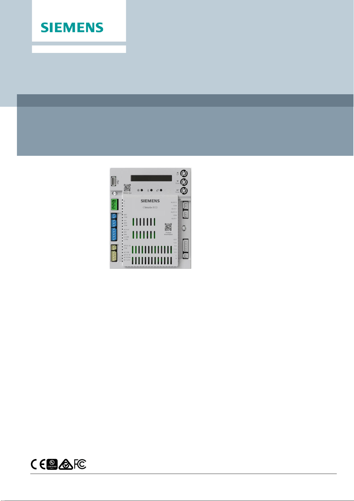
Siemens Climatix ECO User manual
Other Siemens Industrial Equipment manuals

Siemens
Siemens BD01-AK IP55 Series User manual

Siemens
Siemens 3VT9300-8LA00 User manual

Siemens
Siemens 3SU1400-2H 10-6AA0 Series User manual

Siemens
Siemens SIMOCODE pro 3UF70 0-1A 00-0 Series User manual

Siemens
Siemens 3VM9 0JA1 Series User manual

Siemens
Siemens SITRANS F M Verificator User manual

Siemens
Siemens SIMATIC ET 200SP User manual

Siemens
Siemens SPCW110 User manual

Siemens
Siemens 3VA9137-0CK12 User manual

Siemens
Siemens SIRIUS 3RT126 A/N Series User manual

Siemens
Siemens BD2 User manual

Siemens
Siemens RUGGEDCOM WIN7235 User manual

Siemens
Siemens 411625A00 User manual

Siemens
Siemens 3WN6 User manual

Siemens
Siemens 3VT Series User manual

Siemens
Siemens SIRIUS 3RT263-1 Series User manual

Siemens
Siemens RUGGEDCOM RX1510 User manual

Siemens
Siemens milltronics ILE-37 User guide

Siemens
Siemens SIMATIC PROFINET Parts list manual

Siemens
Siemens MICROMASTER 440 User manual