Siemens GAS-Guard 8 Instruction Manual

SIEMENS
GAS-Guard 8 and GAS-Guard 3
Operations and Maintenance Guide
810-1734-00 Rev A

Corporate Office: +1 (800) 880-2552
Technical Support: +1 (866) 273-7763
Copyright © 2006 Serveron Corporation
All rights reserved
Serveron, TrueGas, and LoadGuide are registered trademarks of Serveron Corporation.
All other trademarks, registered trademarks, service marks, and trade names are the
property of their respective owners.

810-1734-00 Rev A GAS-Guard 8 and GAS-Guard 3 Operations and Maintenance Guide
1 of 18
Table of Contents
Introduction..............................................................................................................................................................3
Product Symbols......................................................................................................................................................4
Operation..................................................................................................................................................................5
Calibration ............................................................................................................................................................5
Alarm Settings......................................................................................................................................................5
New transformers or transformers with no previous gas data:.................................................................................6
Transformers with a stable gassing history:.................................................................................................................6
Gassing Transformers which have been degassed:.....................................................................................................7
Transformers with an unstable gassing history which have not been degassed: ...................................................7
Viewing GAS-Guard Data..................................................................................................................................7
Front panel lights (Indicators) ...........................................................................................................................8
Turning the GAS-Guard On/Off ......................................................................................................................9
Manual DGA Sampling ....................................................................................................................................10
Operational Parameters ....................................................................................................................................10
Maintenance ...........................................................................................................................................................11
Helium and Verification Gas ...........................................................................................................................11
Helium Gas .....................................................................................................................................................................11
Helium Dryer..................................................................................................................................................................11
Helium Cylinder and Dryer Removal and Replacement..........................................................................................11
Verification Gas ..............................................................................................................................................................13
Verification Gas Cylinder Removal and Replacement..............................................................................................13
Leak Check Fittings ...........................................................................................................................................14
Replacing Fuses..................................................................................................................................................14
Oil Filter Service.................................................................................................................................................15
Customer Replaceable Units (CRU’s).............................................................................................................16
Cleaning ..............................................................................................................................................................16
Internal Cleaning............................................................................................................................................................ 16
External Cleaning...........................................................................................................................................................16
Return Shipping Instructions...............................................................................................................................17
Forms.......................................................................................................................................................................18
Verification Cylinder Data Sheet.....................................................................................................................18
Table of Figures
Figure 1: Siemens GAS-Guard...............................................................................................................................3
Figure 2: Oil shut off valve.....................................................................................................................................9
Figure 3: DGA sample port ..................................................................................................................................10
Figure 4: Installed verification cylinder..............................................................................................................14
Figure 5: Filter assembly.......................................................................................................................................15
Figure 6: Internal foam support...........................................................................................................................17

GAS-Guard 8 and GAS-Guard 3 Operations and Maintenance Guide 810-1734-00 Rev A
2 of 18
Table of Tables
Table 1: Product Symbols .......................................................................................................................................4
Table 2: Recommended caution/alarm settings for transformers with no previous gas data.....................6
Table 3: Recommended caution/alarm settings for transformers with a stable gassing history.................6
Table 4: Recommended caution/alarm settings for gassing transformers after degassing..........................7
Table 5: Front panel lights ......................................................................................................................................8
Table 6: Customer Replaceable Units .................................................................................................................16
Table 7: Verification cylinder datasheet .............................................................................................................18

810-1734-00 Rev A GAS-Guard 8 and GAS-Guard 3 Operations and Maintenance Guide
3 of 18
Introduction
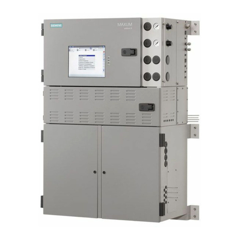
The Siemens GAS-Guard is an on-line laboratory-grade gas chromatograph. The GAS-Guard detects
and measures fault gases found in the cooling oil of power transformers. The GAS-Guard is designed
and constructed to operate under those environmental conditions typical of a power substation or
generating facility.
Figure 1: Siemens GAS-Guard

GAS-Guard 8 and GAS-Guard 3 Operations and Maintenance Guide 810-1734-00 Rev A
4 of 18
Product Symbols
The following symbols are used throughout the GAS-Guard or accessories. They are defined by the
International Electrotechnical Commission, IEC 878 and IEC 417A. It is important for safety reasons to
have an understanding of their representation.
Voltage Output
Voltage Input
Fuse
High Voltage
Caution: Refer to GAS-Guard Installation Guide and accompanying
documentation.
Protective earth (ground)
V~ Alternating Current and Voltage
HConnect to mains live conductor (brown)
LConnect to mains neutral conductor (blue)
__I__
O
The Iposition indicates the power switch is ON
The Oposition indicates the power switch is OFF
This device has been tested and certified by the Canadian Standards
Association International to comply with applicable U.S. and
Canadian safety standards.
Table 1: Product Symbols
WARNING statements in this manual identify conditions or practices that could result in personal
injury.
CAUTION statements in this manual identify conditions or practices that could result in damage to the
equipment or other property.
NOTE statements provide additional important information.

810-1734-00 Rev A GAS-Guard 8 and GAS-Guard 3 Operations and Maintenance Guide
5 of 18
Operation
Once installed, the Siemens GAS-Guard requires very little setup before operation commences. To
retrieve DGA data from the GAS-Guard, set caution/alarm levels, sampling schedules etc. use either
GAS-Guard View software or the Serveron Monitoring Service (SMS). Refer to the GAS-Guard View
Software User’s Manual or the SMS User’s Guide. For more information, manuals are available for
Calibration
Every Siemens GAS-Guard is calibrated at the factory. Following installation and commissioning, the
GAS-Guard’s auto-calibration feature verifies calibration automatically every three days. Siemens
recommends confirming calibration of your GAS-Guard every six months by viewing the ‘Verification
PPM in Gas’ graph in GAS-Guard View (Graph Tools→Maintenance→Verification Data). A manual
recalibration should not be required unless a new certified verification cylinder is installed,
approximately once every three years. If Siemens has connectivity to the GAS-Guard during the
standard warranty period (12-months from date of shipment) Siemens will periodically confirm
calibration of the GAS-Guard as well.
Note: For Serveron Monitoring Service customers, upon installing a new verification
cylinder fill out and return the Verification Cylinder Datasheet located at the end of this
document and return it to Technical Support.
Alarm Settings
Following installation of the GAS-Guard and after an initial 24 hour stabilization period, the gas
caution and alarm levels can be set in the GAS-Guard. These levels can be set using the GAS-Guard
View software which was included with your GAS-Guard or by the Serveron Monitoring Service.
There are no universal rules regarding the values at which to set the caution and alarm levels in the
GAS-Guard. In the most general case caution and alarm settings are disabled while the
GAS-Guard runs for approximately thirty (30) days to establish gassing trends and a baseline PPM
level for each of the fault gases. After the GAS-Guard PPM data has been established, you can use the
history to set the caution and alarm levels directly or consult with the support group at
The following guidelines may be useful for setting the initial gas caution and alarm levels. Keep in
mind that these are recommendations. The appropriate caution and alarm settings for your
GAS-Guard may vary from these recommendations.

GAS-Guard 8 and GAS-Guard 3 Operations and Maintenance Guide 810-1734-00 Rev A
6 of 18
New transformers or transformers with no previous gas data:
Set the GAS-Guard caution level to 50% and the alarm level to 100% of the low-end CAUTION ppm
limits proposed by IEEE PC57.104 Draft 11, published April 21, 2004; except acetylene, as noted below.
Gas Caution PPM Alarm PPM Notes:
Hydrogen 50 100
Methane 60 120
Acetylene 2 5 Per Draft 11
Ethylene 25 50
Ethane 33 65
Carbon Monoxide 175 350
Carbon Dioxide 1750 3500
Oxygen baseline+10% Baseline+20% above initial measured PPM
Table 2: Recommended caution/alarm settings for transformers with no previous gas data
Transformers with a stable gassing history:
Use the GAS-Guard to measure the transformer oil for thirty (30) days in order to establish baseline
levels of the eight fault gases. Set the GAS-Guard caution/alarms levels to the measured baseline levels
+ value (PPM) shown below.
Gas Caution PPM
+value (PPM)
Alarm PPM
+value (PPM) Notes:
Hydrogen +50 +100
Methane +60 +120
Acetylene +2 +5
Ethylene +25 +50
Ethane +33 +65
Carbon Monoxide +175 +350
Carbon Dioxide +1750 +3500
Oxygen baseline+10% Baseline+20% above initial measured PPM
Table 3: Recommended caution/alarm settings for transformers with a stable gassing history

810-1734-00 Rev A GAS-Guard 8 and GAS-Guard 3 Operations and Maintenance Guide
7 of 18
Gassing Transformers which have been degassed:
Set the caution level to 50% and the alarm level to 100% of the low-end CAUTION ppm limits
proposed by IEEE PC57.104 Draft 11, published April 21, 2004; except acetylene, as noted below.
Gas Caution PPM Alarm PPM Notes:
Hydrogen 50 100
Methane 60 120
Acetylene 2 5 Per Draft 11
Ethylene 25 50
Ethane 33 65
Carbon Monoxide 175 350
Carbon Dioxide 1750 3500
Oxygen baseline+10% Baseline+20% above initial measured PPM
Table 4: Recommended caution/alarm settings for gassing transformers after degassing
Transformers with an unstable gassing history which have not been
degassed:
There are no recommendations possible for transformers in this category. In order to establish the
caution and alarm levels, allow the GAS-Guard to run for thirty (30) days to establish gassing trends
and baseline measurements. After this data has been collected, you should consult with Siemens
([email protected]) to determine the appropriate caution and alarm settings for the transformer.
Viewing GAS-Guard Data
The GAS-Guard data can be viewed using the supplied GAS-Guard View software or the optional
Serveron Monitoring Service Client software. A copy of the GAS-Guard View software and user’s
manual can be found on the CD that shipped with the GAS-Guard. Alternatively, the GAS-Guard can
present data to SCADA systems using DNP3 or Modbus protocols. Please contact a Siemens
representative for further information regarding the Serveron Monitoring Service or to integrate the
GAS-Guard with a SCADA system

GAS-Guard 8 and GAS-Guard 3 Operations and Maintenance Guide 810-1734-00 Rev A
8 of 18
Front panel lights (Indicators)
The Siemens GAS-Guard has three colored lights (LED’s) located on the front panel. These lights are
described in the following Table as they appear on the front panel, from top to bottom.
Light Notes:
Alarm The GAS-Guard has detected one or more gas values equal to or
greater than their respective alarm settings.
Service
The GAS-Guard needs service. The service indicator is activated by
a number of GAS-Guard-specific parameters. For cause
identification proceed as follows-
GAS-Guard View:
Open GAS-Guard View program and update the unit database. After
updating the database open the event-log and view recorded event
condition.
Serveron Monitoring Service:
Open the Serveron Monitoring Service Client program and view the
event log. Contact Technical Support group at
Note: Depending on the cause for Service, the GAS-Guard may
need to perform an analysis before the blue Service LED is turned
OFF.
Power The GAS-Guard is ON.
Table 5: Front panel lights

810-1734-00 Rev A GAS-Guard 8 and GAS-Guard 3 Operations and Maintenance Guide
9 of 18
Turning the GAS-Guard On/Off
CAUTION: Always ensure helium is being supplied to the analyzer. Never leave the helium
inlet to the GAS-Guard exposed to atmosphere.
CAUTION: The GAS-Guard is designed to operate continuously. When powering down the
GAS-Guard for extended periods of time (more than 24 hours), always close the oil supply and
return valves to the analyzer.
To isolate (shut off) the oil inlet and oil outlet ports, close the transformer oil supply and return valves
or close the Siemens manual DGA (sample port/oil shutoff) valve as well as the Siemens oil return
valve located on the bleed fixture.
The figure below is a typical example of one of these valves. There are at least two valves per
installation, one for the inlet and one for the outlet. The exact location and number of these valves will
vary by installation. The valve is shown in the ON position in the following figure.
Figure 2: Oil shut off valve
For whatever reason, if the GAS-Guard is consistently unable to complete its sample runs, Siemens
recommends powering down the GAS-Guard and closing the supply and return valves (described
above) until the exact nature of the problem is understood and/or corrected. This will ensure no
damage is caused to the GAS-Guard.

GAS-Guard 8 and GAS-Guard 3 Operations and Maintenance Guide 810-1734-00 Rev A
10 of 18
Manual DGA Sampling
A manual DGA sample port is installed in-line with the GAS-Guard oil supply tubing. Siemens
recommends this port for correlation of GAS-Guard data to manual DGA data. The location of the
sample port will vary by installation. The sample port provided with the GAS-Guard is a ¼-in locking
valve with a 1/4-in FNPT fitting. No special procedures are required when obtaining a manual DGA
sample.
Figure 3: DGA sample port
Operational Parameters
Please see the “Siemens GAS-Guard Data Sheet” available online at www.serveron.com.

810-1734-00 Rev A GAS-Guard 8 and GAS-Guard 3 Operations and Maintenance Guide
11 of 18
Maintenance
The Siemens GAS-Guard has been designed to keep maintenance to a minimum. The following will
help you determine the best service plan.
Helium and Verification Gas
Helium Gas
The helium gas cylinder will last greater than four (4) years based on the default four hour sampling
interval. It is important that the gauge on the regulator be checked quarterly and a leak-check solution
applied to fittings biannually to ensure no leaks have developed. The helium cylinder should be
replaced when the pressure gauge reads less than 150psi (10.34 bar).
Helium Dryer
The helium dryer will last greater than four (4) years based on the default four hour sampling interval.
A leak-check solution should be applied to the helium dryer fittings bi-annually to ensure no leaks
have developed. The helium dryer should be replaced when the helium cylinder is replaced.
Helium Cylinder and Dryer Removal and Replacement
WARNING: When full, the helium cylinder is pressured to greater than 2000psi (138
bar). Helium is regulated to 80psi (5.5 bar), nominal, before entering the GAS-Guard,
Always follow Compressed Gas Association (CGA) guidelines when handling and
transporting compressed gases.
CAUTION: Use of helium other than 99.9999% pure research or chromatographic grade
with less than (0.2 ppm) H2O content will VOID the GAS-Guard warranty.
1) Turn off power to the GAS-Guard by opening the GAS-Guard door and toggling the power
switch located in the upper right hand corner to the OFF position.
2) Turn the helium cylinder valve clockwise to the fully OFF position.
3) Using a 7/16-in wrench, remove the 1/8-in helium inlet and outlet lines from the top and
bottom of the helium dryer.
WARNING: A small amount of high-pressure helium will be released upon loosening
the fitting.
4) Using a suitable wrench, remove the helium regulator from the cylinder valve.

GAS-Guard 8 and GAS-Guard 3 Operations and Maintenance Guide 810-1734-00 Rev A
12 of 18
5) Carefully support the regulator to prevent any damage to the 1/8-in helium line or
regulator.
CAUTION: It is extremely important that no water or other foreign contaminates be
allowed to enter the open regulator fitting or tubing.
6) Remove the helium cylinder from its mounting bracket.
7) Remove the helium dryer from its mounting clips.
8) Verify the replacement cylinder meets the following specifications:
Chromatographic grade helium
99.9999% pure/Grade (6.0)
Less than 0.2 ppm H2O
CGA-580 fitting
9) Position the new helium cylinder in the mounting bracket and secure the cylinder in place.
10) Reinstall the regulator onto the helium cylinder. Do not use Teflon tape or pipe dope.
11) Orient the gauge vertically and tighten the CGA fitting.
12) If necessary, reorient the helium cylinder so that the gauge on the regulator can be clearly
seen.
13) Install the new helium dryer in the mounting clips. The dryer is not flow directional.
Note: Do not remove the helium dryer plugs at this time.
14) Verify the helium regulator shutoff valve is closed and slowly turn the valve located on top
of the helium cylinder fully counterclockwise (open).
15) Slowly turn helium regulator shutoff valve counterclockwise (open) until helium begins to
flow. At this point, gas should be escaping from the stainless steel tubing.
CAUTION: Do not open the regulator shutoff valve completely to regulate the helium flow.
16) Leaving the helium flowing, remove the top helium dryer plug and attach the free end of
the 10-ft helium line to the top of the helium dryer.
17) With the helium continuing to flow reinstall the line to the bottom of the helium dryer.
18) Now turn the regulator shutoff valve fully counterclockwise (open).
19) Confirm all four helium connections and the helium regulator to helium tank connections
are leak-tight by applying a leak-check solution to the fittings.
Note: The leak check is very important as even the smallest leak can substantially reduce the
life of the helium cylinder.
The helium regulator outlet pressure is preset at 80psi (5.5 bar), nominal, and requires no adjustment.

810-1734-00 Rev A GAS-Guard 8 and GAS-Guard 3 Operations and Maintenance Guide
13 of 18
Verification Gas
The verification gas certification is three (3) years and the cylinder holds enough gas for over 4 years
worth of verification runs based on the default ‘every three days’ sampling interval. It is important that
the gauge on the regulator be checked quarterly and a leak-check solution applied to fittings bi-
annually to insure no leaks have developed. The verification cylinder should be replaced when the
high pressure gauge reads less than 25psi (1.72 bar).
CAUTION: Use of verification gas that does not meet Siemens specifications will VOID
the GAS-Guard warranty.
Verification Gas Cylinder Removal and Replacement
WARNING: When full, the verification gas cylinder is pressured to greater than 500psi (34 bar).
Verification gas is regulated to 8psi (0.5 bar), nominal, before entering the GAS-Guard. Always
follow Compressed Gas Association (CGA) guidelines when handling and transporting
compressed gases.
The verification gas cylinder is used to automatically verify and calibrate the GAS-Guard. The cylinder
contains a certified NIST-traceable concentration of the eight-transformer fault gases measured by the
GAS-Guard.
1) Turn off power to the GAS-Guard by opening the GAS-Guard door and toggling the power
switch located in the upper right hand corner to the OFF position.
2) Turn the verification cylinder tank valve to the fully OFF (clockwise) position.
3) Using a 9/16-in wrench loosen the verification cylinder to regulator union.
WARNING: A small amount of high-pressure verification gas will be released upon loosening
the fitting.
4) While supporting the verification cylinder release the Velcro strap retaining the verification
cylinder in the bracket.
5) Install the new verification cylinder into the mounting bracket and secure using the Velcro
strap.
6) Connect the cylinder to the regulator union and tighten.
7) Turn the knob on the top of the verification cylinder counterclockwise until it is fully open.
The regulator requires no pressure adjustment.
8) Confirm that the bottle to regulator connection is leak-tight by applying a leak-check
solution to the fitting. Wipe away any excess leak-check solution.
Note: The leak check is very important, as even the smallest leak can substantially reduce the
life of the verification cylinder.

GAS-Guard 8 and GAS-Guard 3 Operations and Maintenance Guide 810-1734-00 Rev A
14 of 18
9) For Serveron Monitoring Service users, please complete and return the Verification cylinder
replaced.
Figure 4: Installed verification cylinder
Leak Check Fittings
After the first month of continuous use, all regulator, gas and oil fittings should be checked for leaks. A
semi-annual check of these fittings is recommended following the one month initial check.
Replacing Fuses
The GAS-Guard has a variable input power supply capable of receiving input of 115VAC or 230VAC
±15%, 50/60 Hz. Current draw is 6A max. at 115VAC and 3A max. at 230VAC. There are three
4A/250V type 3AG (T) fuses installed for the power supply (line and neutral) and the GAS-Guard’s
enclosure heater (line).
CAUTION: Replace fuses with same type and rating only.

810-1734-00 Rev A GAS-Guard 8 and GAS-Guard 3 Operations and Maintenance Guide
15 of 18
Oil Filter Service
The GAS-Guard uses two inline screen type oil filters. Under normal operation, no filter maintenance is
required. If service is require, the filter consist of three main parts: the filter housing, filter screen and
the filter cap. For filter service proceed as follows:
1) Turn off power to the GAS-Guard by opening the GAS-Guard door and toggling the power
switch located in the upper right hand corner to the OFF position.
2) Loosen the filter cap while supporting the filter housing with an adjustable end wrench. The
exact filter location will vary by installation.
3) After loosening the filter cap slowly back off the cap until transformer oil starts flowing out
the purge hole located on the side of the filter cap.
4) Let the oil continue to flow until a clear stream of oil void of any contaminates is visible.
5) Tighten filter cap.
6) Turn on power to GAS-Guard.
Figure 5: Filter assembly

GAS-Guard 8 and GAS-Guard 3 Operations and Maintenance Guide 810-1734-00 Rev A
16 of 18
Customer Replaceable Units (CRU’s)
Customer Replaceable Units (CRU’s) are defined as customer replaceable parts onsite without
decommissioning the GAS-Guard.
Part # Description
270-0004-XX Helium Dryer
290-0020-XX Regulator, CAL,
290-0017-XX Cylinder, Verification
292-0018-XX Regulator Helium
292-0019-XX Regulator Helium w/ Pressure Switch
370-0025-XX LED, Front Panel, Green
370-0026-XX LED, Front Panel, Red
370-0027-XX LED, Front Panel, Blue
430-0032-XX Fuse, TD, 4 Amps, 1/4" x 1 1/4"
750-0076-XX Column Assembly, GAS-Guard 8
750-0084-XX Assy, Power Supply
750-0090-XX Column Assembly, GAS-Guard 3
250-0130-XX Filter, Oil
R750-0076-XX Replacement Column Assembly1, GAS-Guard 8
R750-0084-XX Refurbished Power Supply Assy
Table 6: Customer Replaceable Units
Cleaning
Internal Cleaning
No internal cleaning of the GAS-Guard is required; doing so may cause damage the internal
components and void the warranty.
External Cleaning
No external cleaning of the GAS-Guard is required. If external cleaning is desired, water is the only
recommended cleaning solution. Direct spray of high-pressure water onto the GAS-Guard door seal,
LED’s, oil/helium bulkhead fittings and cable glands should be avoided.
1GAS-Guard 3 does not require replacement column assembly

810-1734-00 Rev A GAS-Guard 8 and GAS-Guard 3 Operations and Maintenance Guide
17 of 18
Return Shipping Instructions
Prior to returning parts to Siemens a Return Material Authorization (RMA) number must be obtained
from Siemens technical support:
Technical Support: +1 (866) 273-7763
Returned items should be shipped in the original packaging or like packaging to avoid shipping
damage. If original packaging or like packaging is not available contact Technical Support for shipping
assistance.
Warning: Shipping of the GAS-Guard without installing the internal foam support, part #
010-0038-XX, can cause damage to the GAS-Guard and void the warranty.
Figure 6: Internal foam support

GAS-Guard 8 and GAS-Guard 3 Operations and Maintenance Guide 810-1734-00 Rev A
18 of 18
Forms
Verification Cylinder Data Sheet
Upon successful installation of your verification cylinder; please complete and fax or e-
mail this Verification Cylinder Data Sheet to Technical Support at:
+1 (503) 924-3290 fax
Attn: Siemens Product Support
From:
Customer Information
Company:
Site:
Site Address:
City, State and Zip:
Country:
Gas Cylinder Information
Installer’s Name:
Installation Date:
GAS-Guard Serial
Number:
Helium high pressure
gauge (psig):
Verification high pressure
gauge (psig):
Verification Cylinder
Lot Number: Verification Cylinder
Manufacture Date:
Verification Cylinder
Gas Components Certified Concentrations
Hydrogen H2ppm
Oxygen O2ppm
Methane CH4ppm
Carbon Monoxide CO ppm
Carbon Dioxide CO2ppm
Ethylene C2H4ppm
Ethane C2H6ppm
Acetylene C2H2ppm
Table 7: Verification cylinder datasheet
This manual suits for next models
1
Table of contents
Other Siemens Laboratory Equipment manuals

Siemens
Siemens Maxum II User manual

Siemens
Siemens Healthineers ADVIA User manual

Siemens
Siemens PGC 302 Edition II User manual

Siemens
Siemens ADVIA 2400 Manual

Siemens
Siemens ADVIA LabCell User manual

Siemens
Siemens Hematek User manual

Siemens
Siemens PFA-100 System User manual

Siemens
Siemens Simatic MV220 User manual

Siemens
Siemens ADVIA Centaur Quick start guide

Siemens
Siemens Maxum II User manual