Yamato IL603 User manual

Low Temperature
Constant-Temperature Chamber
Air Jacket System
Model IL603
Instruction Manual
First edition
●Thank you very much for purchasing this Yamato
IL603 low temperature constant-temperature chamber.
●Please read the “Operating Instructions” and
“Warranty” before operating this unit to assure proper
operation. After reading these documents, be sure to
store them securely together with the “Warranty” at a
handy place for future reference.
Warning: Before operating the unit, be sure
to read carefully and fully
understand important warnings in
the operating instructions.
Yamato Scientific America Inc.
Santa Clara,CA
Printed on recycled paper.

Contents
1. Safety precautions ................................................................. 1
Explanation of pictograms ............................................................. 1
List of symbols ....................................................................... 2
Warning・Cautions ................................................................... 3
2. Before operating the unit ........................................................... 4
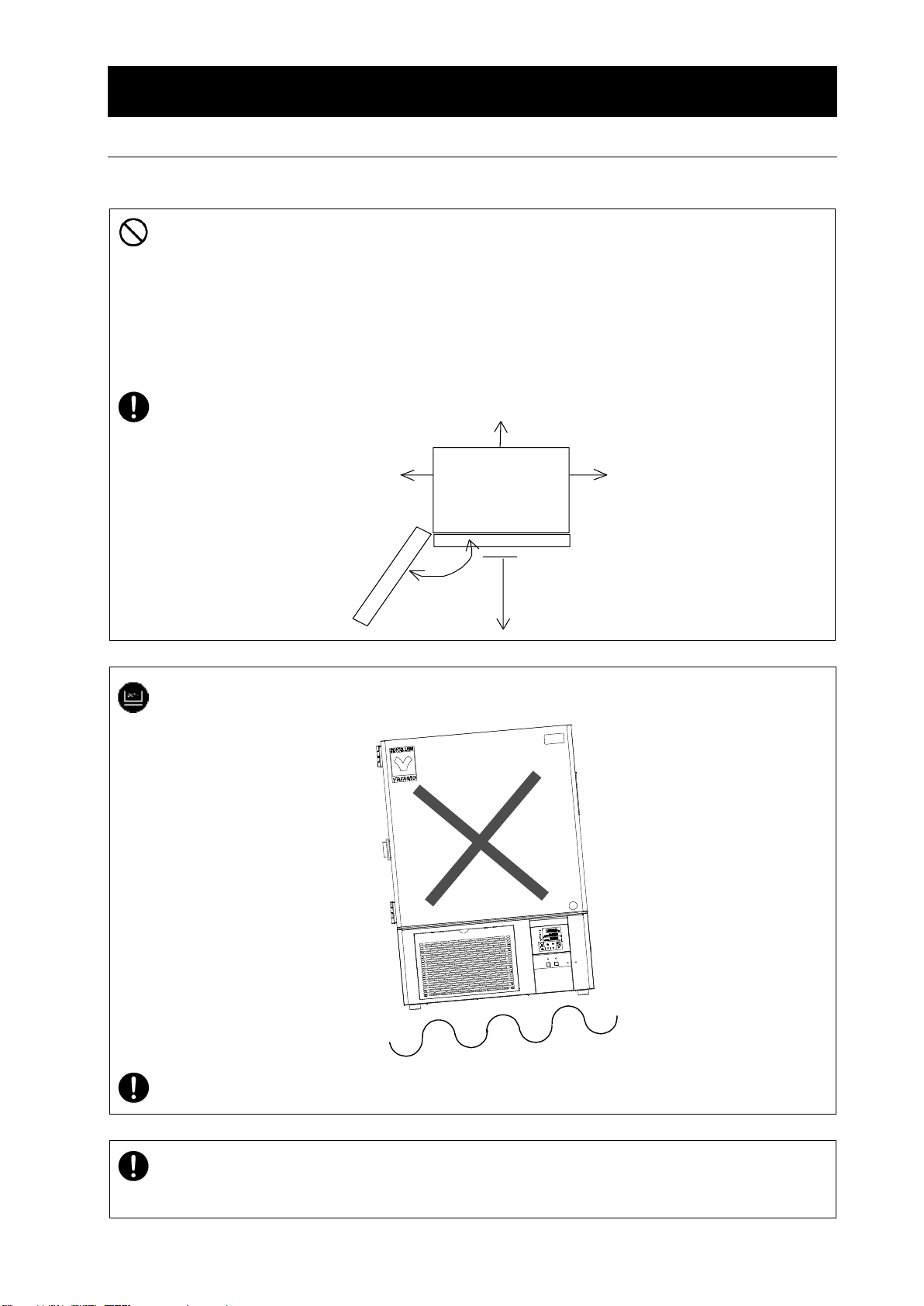
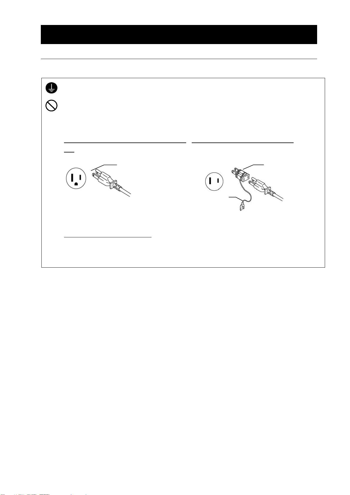
Precautions when installing the unit ..................................................... 4
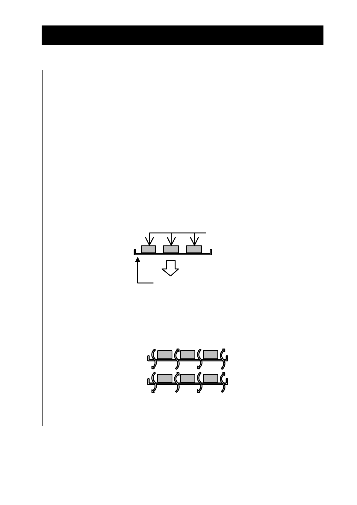
Installation procedures/precautions...................................................... 8
About defrosting of the freezer......................................................... 10
3. Names and functions of parts ...................................................... 12
Main unit ........................................................................... 12
Operation panel ..................................................................... 13
Characters of the Controller ........................................................... 15
4. Operation Method................................................................. 16
Operation Mode and Function List ..................................................... 16
Operation Mode, Function Setting Key, and Characters ................................... 20
Setting of Overheating Prevention Device ............................................... 21
Fixed Temperature Operation.......................................................... 23
Quick Auto Stop Operation............................................................ 25
Auto Stop Operation ................................................................. 27
Auto Start Operation ................................................................. 29
Calibration Offset Function............................................................ 31
Lock Function....................................................................... 32
Freezer operation mode function....................................................... 33
Temperature rise/fall characteristics .................................................... 34
Introduction of optional parts .......................................................... 35
Temperature Output Terminal.......................................................... 36
RS485 Communication Function....................................................... 38
5. Cautions on handling.............................................................. 50
6. Maintenance procedures........................................................... 52
Daily inspection/maintenance.......................................................... 52
7. When the unit is not to be used for a long time or when disposing ..................... 54
When the unit is not to be used for a long time or when disposing........................... 54
Notes about disposition............................................................... 54
8. Troubleshooting .................................................................. 55
Safety device and error codes......................................................... 55
When a malfunction is suspected ...................................................... 56
9. After sales service and warranty.................................................... 57
When requesting a repair ............................................................. 57
10. Specifications ................................................................... 58
11. Wiring diagram .................................................................. 59
12. Replacement parts list............................................................ 60
13. List of dangerous materials....................................................... 61
14. Standard installation manual ...................................................... 62

1
1. Safety precautions
Explanation of pictograms
About pictograms
A variety of pictograms are indicated in this operating instruction and on
products for safe operation. Possible results from improper operation
ignoring them are as follows.
Be sure to fully understand the descriptions below before proceeding to the
text.
Warning
Caution
Indicates a situation which may result in minor injury (Note 2) and
property damages (Note 3.)
(Note 1)Serious injurymeans a wound, an electrical shock, a bone fracture or intoxication that may
leave after effects or require hospitalization or outpatient visits for a long time.
(Note 2)Minor injury means a wound or an electrical shock that does not require hospitalization or
outpatient visits for a long time.
(Note 3)Property damage means damage to facilities, devices and buildings or other properties.
Meanings of pictograms
This pictogram indicates a matter that encourages the user to adhere to warning
(“caution”included).
Specific description of warning is indicated near this pictogram.
This pictogram indicates prohibitions
Specific prohibition is indicated near this pictogram.
This pictogram indicates matters that the user must perform
Specific instruction is indicated near this pictogram.
Indicates a situation which may result in death or serious injury (Note 1.)

2
1. Safety precautions
List of symbols
Warning
General warnings
Danger!: High
voltage
Danger!: High
temperature
Danger!: Moving
part
Danger!: Hazard
of explosion
Caution
General cautions
Electrical shock!
Burning!
Caution for no
liquid heating!
Caution for water
leak!
For water only
Poisonous
material
Prohibitions
General bans
Fire ban
Do not
disassemble
Do not touch
Compulsions
General
compulsions
Connect ground
wire
Install levelly
Pulloutthepower
plug
Regular
inspection

3
1. Safety precautions
Warning・Cautions
Warning
Never operate the unit in an atmosphere containing flammable or explosive gas
Never operate the unit in an atmosphere containing flammable or explosive gas.
Otherwise, an explosion or a fire may result since the unit is not explosion-proof.
See section “13. List of dangerous materials” on page 61.
Be sure to connect the ground wire.
Be sure to connect the ground wire correctly. Otherwise, electrical leak may result and cause an
electrical shock or a fire.
Ban on operation when an abnormality occurs
When a smoke or an unusual odor is seen or sensed, immediately turn the ELB on the main unit off
and pull out the power plug.A fire or an electrical shock may result.
Never use electrical power cords bundled.
When these are used bundled, they might overheat causing a fire.
Take care not to damage electrical power cords.
Avoid tightly bend, pull with a strong force or twist to prevent electrical power cords from damaging.
Afire or an electrical shock may result.
Never use an explosive or a flammable material with this unit.
Never use an explosive material, a flammable material or a material containing them. An explosion
or an electrical shock may result.
See section “13. List of dangerous materials” on page 61.
Never try to touch a hot part.
Some parts of the unit are hot during and immediately after operation. Take special care for possible
burning.
Never try to disassemble or alter the unit.
Never try to disassemble or alter the unit.A malfunction, a fire or an electrical shock may result.
Caution
When a thunder is heard.
When a thunder is heard, turn the main power off immediately. A malfunction, fire or an electrical
shock may result.

4
2. Before operating the unit
Precautions when installing the unit
1. Carefully select an installation site.
Take special care not to install the unit at a place described below:
・Uneven surfaces or dirty surfaces
・Where flammable gas or corrosive gas exists
・Where the ambient temperature is 35℃or more
・Where temperature changes severely
・Where humidity is high
・Where subject to direct sunlight
・Where vibration is severe
・Outdoors
Install this unit at a place with spaces shown below.
15cm
or
more
15cm
or
more
Front
15cm or more
1m or more
2. Install the unit on a level surface.
Install the unit on a level surface. If the whole bottom surface of the unit does not contact
the surface evenly, vibrations or noises may result. This might cause unexpected
troubles or malfunctions.
The unit weight is approx. 109 kg.
When lifting the unit for transportation and installation, carefully handle it by at least two
people.
3. Installation
The unit might fall down or move by an earthquake or an impact resulting a personal injury.
We recommend making safety measures such as to avoid installing the unit at a place other
than busy places.

5
2. Before operating the unit
Precautions when installing the unit
4. Secure sufficient ventilation for the unit.
Do not operate the unit when its side panels and vent holes are blocked.
Internal temperature of the unit will rise degrading the performance and an accident, a
malfunction or a fire may result.
5. Do not operate the unit at such a place that may subject to splash.
Do not operate the unit at such a place that may subject to splash. Liquid entering the inside
may cause an accident, a malfunction, an electrical shock or a fire.
6. Never operate the unit in an atmosphere containing flammable or explosive gas.
Never operate the unit in an atmosphere containing flammable or explosive gas. Since the
unit is not explosion-proof, an arc is discharged when switching the ELB “ON” and “OFF” and
during operation and a fire or an explosion may result.
See the section “13. List of dangerous materials on page 61 for flammable and explosive
gases.
Explosive
gas
Flammable gas

6
2. Before operating the unit
Precautions when installing the unit
7. Be sure to connect the power plug to the dedicated power distribution panel or a wall
outlet.
Use a power distribution panel or a wall outlet that meets the electrical capacity of the unit.
Electrical capacity:
IL603 115VAC 11.5A
*When the unit will not start even when you turn the Electric Leakage Breaker to “ON”, check for
low main voltage or if the unit is connected to the same power supply line as other devices and
connect it to another line if necessary.
Avoid connecting too many devices using a branching outlet or extending a wire with a cord reel or
refrigerating function and temperature controlling function may degrade due to voltage drop.
Do not connect the unit to any parts or lines other than a correct power supply line such as a
gas pipe, a water pipe or a telephone line.
Otherwise, an accident or a malfunction may result.
8. Handling of a power cord
Never use electrical power cords bundled. When these are used bundled, they might overheat
causing a fire.
Do not convert, forcibly bend, twist or pull the power cord. Otherwise, a fire or an electrical
shock may result.
Do not place the power cord under a desk or a chair, or sand between objects to avoid it from
being damaged.
Otherwise, a fire or an electrical shock may result.
Do not place the power cord close to a stove or other heat generating device. Sheath of the
cord may burn and result in a fire or an electrical shock.
If the power cord should be damaged (exposure of core wire or disconnection), immediately turn
the ELB off, turn the power supply off and ask your dealer to replace the cord. If the unit is
operated with a damaged power cord, a fire or an electrical shock may result.
Connect the power cord to an appropriate wall outlet.

7
2. Before operating the unit
Precautions when installing the unit
9. Be sure to connect the ground wire.
・Be sure to connect the earth wire (the green core wire of the power cord) to the earth plug
or the earth terminal to prevent an electric shock from electric leakage.
・Never connect the earth wire to a gas pipe or a water pipe. Otherwise, a fire may result.
・Never connect the earth wire to an earth plug of a telephone line or a lightning rod.
Otherwise, a fire or an electric shock may result.
・Never use a branch outlet which may generate heat and cause a dangerous situation.
We recommend use of a ground type outlet
tap.
Outlet with an earth pole
When there is no ground terminal.
●In this case, class D grounding work is
necessary and please consult your dealer or
our customer service center.
When a bipolar type outlet tap is used
接地アダプタ
●Insert the ground adaptor included as an option,
into a power plug confirming the polarity of the
outlet. Connect the grounding wire (green) of the
ground adaptor to the ground terminal on the
power supply equipment.
w
G
Earth electrode
3-polar power plug with
earth pole
To 2-pole 115V
power supply
Earth adaptor
3-polar power plug with
earth pole
Earth wire
W

8
2. Before operating the unit
Installation procedures/precautions
(1)
Select an installation site.
Make sure that the four feet completely sit on a flat surface.
(2)
Install a drain pan.
Prepare a drain pan by yourself or purchase an optional OIL24 drain bottle for defrosting
during which water comes out from the drain hose.
(3)
Install shelf boards.
・Install shelf pegs at heights you want on the right and left shelf posts in the internal bath of
the main body.
・Completely push shelf boards by sliding to the end.
*Take care to put each shelf board on correct pairs of right and left shelf pegs.
・Make sure that shelf boards will not fall nor rattle.
・Withstand load of each shelf board is 15 kg in even loading. When putting specimens,
arrange them as dispersed as possible.
Shelf board
Specimen
15kg
・Put specimens with appropriate spaces between them. Too many specimens may prevent
proper temperature control. To assure proper temperature control, put specimens with a
space at least 30% of the shelf board area.
Assure at least 30% of space

9
2. Before operating the unit
Installation procedures/precautions
(4)
Do not put an specimen on the bottom of the internal bath.
・Operating the unit with a specimen directly put on the bottom of the internal bath might
degrade its temperature characteristics. This also may cause corrosion, damage or rust of
the internal bath. Never put any specimen on the bottom surface.
・When putting specimens, take care not to allow them touching the wall on which the heater,
the sensor or other devices are installed. Put specimens on the shelf board included with the
unit.
(5)
Take special care for specimens including:
①Specimen that contains a flammable or explosive component.
・This unit is not explosion-proof. Never attempt to dry or process a specimen that contains a
flammable or explosive component.
②Corrosive specimen
・Take care for handling a corrosive specimen. Although stainless steel is used for major
components of this unit, they might corrode if they are subject to strong acid. Also note
that packing may corrode with acid, alkaline substances, oil, or organic solvent.
③Specimen that contains much moisture
・While operating the unit at a lower temperature, cooling capacity of the evaporator may be
degraded and the set temperature may not be maintained due to too much frost on the
evaporator. When frost is confirmed through the frost observation window at the bottom of
the bath in the unit, perform defrosting.

10
2. Before operating the unit
About defrosting of the freezer
If a lot of frost is generated on the evaporator of the freezer, its freezing capacity may be
compromised and the set temperature may not be maintained. The unit allows the user to
monitor frosting to the evaporator through the frost observation window at the back inside the
bath. Frosting speed will change depending on the conditions below.
(1) Operating temperature ・・・・・・More frost tends to generate when operated at a lower
temperature.
(2) External temperature and humidity ・・・・・・More frost tends to generate at higher external
temperature and humidity.
(3) State of the specimen in the bath ・・・・・・The more water the specimen contains, the more
frost will be generated.
The unit allows the following operation modes as measures against frosting. Select proper
settings depending on the actual operating conditions. These modes will be valid during the
fixed-value operation by pressing the defrost key on the controller operation panel separately
from the fixed-value operation.
1 Manual defrost operation (operation is started manually and stopped automatically)
Carry out defrosting operation when a lot of frost is on the unit. Although defrosting operation
is started manually but it will automatically stop after about 5 minutes with the internal timer.
→See P.18 “Defrost function” for operating procedures.
2 Cyclic defrosting operation (both of starting/stopping of operation are automatic)
When you are going to operate the unit for an extended period of time, it is effective to set a
cyclic defrosting operation. In most cases, frost can be removed by carrying out defrosting
operation for about 5 minutes every day.
*The amount of frost is different according to the operating conditions.
→See P.18 “Defrost function” for operating procedures.
Caution
●While it depends on operating conditions, a 5-minute defrosting will raise the temperature in
the bath by about 4℃and you need to pay attention to possible effects on the specimen you
are using.Also, the temperature indicated might rise by 10℃or more.

11
2. Before operating the unit
About defrosting of the freeze
3 Setting a freezing operation mode (continuous, cycle) of the freezer
Freezer operation mode function allows the user to set the freezer to continuous operation,
cycle operation, or stop.
Continuous operation is used when placing priority on the temperature control precision, in
which mode the lower the set temperature becomes within the range of 0~30℃, the more
likely frost is generated.
In the cyclic operation mode, the freezer will repeat operation (12 min)→pause (8 min) cycles
and the temperature control precision is slightly lower than the continuous operation mode
but can reduce frosting. When the set temperature is 10℃is less, the freezer will
automatically switches to the continuous operation because of its freezing capacity.
You can also reduce drying out of moisture of the specimen by setting to the cyclic operation.
Caution
●Even if the cyclic operation mode is set, frost amount will differ depending on the operating
conditions and it may gradually increase as operating duration becomes longer. When the
amount of frost is large, carry out the defrost operation or the cyclic defrost operation to remove
frost.
Before carrying out defrosting, be sure to place a drain pan to receive meltwater from the drain
hose.

12
3. Names and functions of parts
Main unit
Φ50mm cable port
With silicone plug
Inner door
Door
Magnet packing
ELB
Serial#/rating sticker
Filter
Shelf peg/shelf board
3 sets included as standard
Shelf pillar
Up to 12 shelf boards accepted
Observation window
(for monitoring frosting
on the evaporator
External output terminal
Temperature output terminal
RS485 com terminal
External alarm terminal
Power cord with plug
2.5m
Drain hose
Φ10mm×13mm×1m
Door key
Operation panel
Defrost operation sheet

13
3. Names and functions of parts
Operation panel
No.
Name
Function
①
RUN/STOP Key:
Starts/stops the operation.
②
▲▼ Key:
Uses for rising UP/lowering DOWN the setting value.
③
SUB MENU Key:
Uses for setting the overheating prevention temperature,
calibration offset temperature, or key lock function.
④
ENTER Key:
Settles the inputted value.
⑤
FIXED TEMP Key:
Chooses the fixed temperature operation.
⑥
TIMER Key:
Chooses the timer operation (Quick Auto Stop/Auto Stop/Auto
Start).
⑦
HEATER Lamp:
Lights while the heater works.
⑧
ALARM Lamp:
Lights up when an error occurs. (Buzzer sounds
simultaneously.)
⑨
AUTO STOP Lamp:
Blinks while setting quick auto stop timer or auto stop timer.
Lights while quick auto stop timer or auto stop timer is running.
⑩
AUTO START Lamp:
Blinks while setting auto start timer.
Lights while auto start timer is running.
⑪
FIXED TEMP Lamp:
Blinks while setting fixed temperature operation.
Lights while fixed temperature operation is running.
⑫
Measurement Temperature
Display:
Displays the measured temperature, setting character, alarm
information.
⑬
Setting Temperature
Display:
Displays the setting temperature, setting value for timer mode,
remaining time.
⑭
Overheating Prevention
Temperature Display:
Displays the setting temperature for overheating prevention
device.
ALARM
AUTO STOP
AUTO START
FIXED TEMP.
ENTER
FIXED
TEMP.
TIMER
SUB
MENU
RUN
STOP
SET TEMP.
OVER TEMP.
PROTECTOR
HEATER
⑦
⑧
⑨
⑩
⑪
⑫
⑬
⑭
①
②
③
⑤
⑥
④

14
3. Names and functions of parts
Control panel
No.
Name
Operation/Function
①
MANUAL DEFROST key
Used to activate the manual defrost function.
②
CYCLE DEFROST key
Used to activate the cycle defrost function.
③
Manual defrost lamp
Lights while the manual defrost function is active.
④
Cycle defrost lamp
Lights while the cycle defrost function is active AND
defrosting is active and flashes while the cycle defrost
function is activeAND defrosting is stopped.
④
②
③
①
MANUAL
CYCLE
DEFROST

15
3. Names and functions of parts
Characters of the Controller
The characters controller shows are as follows:
Character
Identifier
Name
Purpose
FiX
Fixed Temperature
Setting Mode
Used for setting the fixed temperature
operation.
Sv
Temperature Setting
Used for setting the temperature.
AStP
Auto Stop Setting
Used for setting the auto stop operation.
AStr
Auto Start Setting
Used for setting the auto start operation.
tim
Time Setting
Used for setting the time.
End
Time-up
Displayed when timer operation is ended.
Refer to Pages 25 .
cAL
Calibration Offset
Setting
Used for inputting the calibration offset
temperature. (Refer to Page 31 "Calibration
Offset Function".)
oH
Overheating
Prevention Setting
Used for setting temperature for overheating
prevention device. (Refer to Page 21 "Setting
of Overheating Prevention Device ".)
LocK
Key Lock
Locks the keys on control panel to protect
from unnecessary operation. (Refer to Page
32 "Lock Function".)
rEFr
Fcnt
Freezer Operation
Mode Function Setting
Used when you prefer more effective
prevention of frosting on the evaporator.
See “Using the freezer operation mode
function”on P.33
* Also refer to Page 20 "Operation Mode, Function Setting Key, and Characters".

16
4. Operation Method
Operation Mode and Function List
The operation modes of the unit are as follows.
No.
Name
Description
Page
1
Fixed Temperature
Operation
Pressing the FIXED TEMP key enters into the fixed
temperature operation setting mode.
Pressing it again enters into the temperature setting mode.
The "▲▼" are used to set temperature.
Pressing the RUN/STOP key starts or stops operation.
P.23
2
Quick Auto Stop
Operation
This operation is used to specify the period up to automatic
stop during operation.
The period up to operation stop can be set by pressing the
TIMER key during fixed temperature operation.
The "▲▼" are used to set the time.
Pressing the RUN/STOP key starts the quick auto stop
operation, activates the timer function and stops the operation
automatically after specified period.
P.25
3
Auto Stop Operation
This operation is used to specify the automatic stop time in
the fixed temperature operation.
Pressing the TIMER key displays "AStP".
The setting temperature "Sv" can be set by pressing the
ENTER key.
The operation time "tim" can be set by pressing it again.
Pressing the RUN/STOP key starts the auto stop operation.
P.27
4
Auto Start Operation
This operation is used to specify the period up to automatic
start after power on.
Pressing the TIMER key displays "AStr".
The setting temperature "Sv" can be set by pressing the
ENTER key.
The operation time "tim" can be set by pressing it again.
Pressing the RUN/STOP key starts the auto start operation.
P.29
※This unit is impossible to be changed the mode during the operation. If the mode requires to be
changed, stop the operation.

17
4. Operation Method
Operation Mode and Function List
The operation functions of this unit are as follows;
No.
Name
Description
Page
1
Overheating
prevention
function
Auto overheating
prevention
function
This function is set to be automatically activated (auto
reset) when the temperature exceeds the setting
temperature by 6℃.
P.21
Independent
overheating
prevention
device
Though the device shares power source, display, and
key input with the controller, it has independent
temperature measurement circuit, CPU, sensor and
output circuit. Overheating prevention temperature
can be set using the operation panel.
The unit stops operation when the device is activated.
The unit starts operation again when the SUB MENU
key is pressed again (manual reset).
2
Calibration offset function
This calibration offset function is for calibrating the
difference occurred between the required in- bath
temperature and control temperature (sensor
temperature) of the controller. This unit can be
calibrated toward either plus side or minus side of the
whole temperature range. Press SUB MENU key to
set this function.
P.31
3
Setting value locking
This function locks the established operation status.
It can be set and cancelled with the SUB MENU key.
Press SUB MENU key to set this function.
P.32
4
Temperature Output Terminal
Transmits and outputs the measured temperature of
the controller at 4 to 20 mA.
P.36
5
RS485 Communication
Function
The function to allow communication between the
VS3 controller and a personal computer or another
unit. An optional RS485-RS232C conversion adapter
is required for external communication.
Asample program is uploaded on our website.
http://www.yamato-net.co.jp/support/program/index.ht
m
P.38

18
4. Operation Method
Operation Mode and Function List
№
Name
Description
6
Defrost function
When a lot of frost sticks to the evaporator during operation at a lower
temperature, its cooling capacity may be compromised and cannot keep
the set temperature.
The model IL603 has an observation window inside the bath to allow the
operator to check how much the evaporator is frosted. The frosting speed
will differ depending on the actual conditions.
(1)Operating
temperature
:Operation at a lower temperature will tend to cause
more frost.
(2)External
temperature/
humidity
:Operation at a higher temperature and a humidity
will tend to cause more frost.
(3)Inside the
bath
:Higher in-bath temperature will tend to cause more
frost.
(For example, when the water content of the
specimen is high.)
The model IL603 supports operation modes below to prevent frosting and
select an operation mode suited to the operating conditions. You can
enable these operation modes by pressing the DEFROST key at the
defrost control assembly below the unit controller independently from the
fixed-temperature operation settings.
1. Manual defrost operation(Operation is started manually and stopped
automatically.)
Perform defrost operation when you have found that a lot of frost on the
evaporator through the frost observation window. Note that temperature
control will be paused during defrost operation.
Although you need to start defrost operation manually, it will
automatically stop after about five minutes with the internal timer.
2. Cycle defrost operation (Both starting and stopping operation are
automatic.)
It is effective to set the cycle defrost operation when you are going to
start a long time operation.
Cycle repeats cycle defrost operation→normal operation→cycle defrost
operation→normal operation→and 24 hours comprises of five minutes
for cycle defrost operation and 23 hours 55 minutes for normal
operation.
Although it depends on the specific operating
conditions, the in-bath temperature will rise beyond the
set temperature during defrost operation and take care
for possible adverse effects on the specimen. At this
time, the temperature on the gauge may rise by 10℃or
more.
(The increase margin will differ depending on the set
temperature, the specimen, or the external
temperature.)
※Reference data:Temperature increase is within about
4℃when set temperature is at 37 ℃and the
external temperature is 20℃.)
Table of contents
Other Yamato Laboratory Equipment manuals

Yamato
Yamato IC103CW User manual

Yamato
Yamato NeoCool Circulator CF301 User manual

Yamato
Yamato BM510 User manual

Yamato
Yamato SK101C User manual

Yamato
Yamato RT200 User manual

Yamato
Yamato BK300 User manual

Yamato
Yamato Fish Analyzer PRO DFA110 User manual

Yamato
Yamato DF411 User manual

Yamato
Yamato SM520 User manual

Yamato
Yamato DL410 User manual

Yamato
Yamato CA300 User manual

Yamato
Yamato SK200C User manual

Yamato
Yamato RE300 User manual

Yamato
Yamato DF410 User manual

Yamato
Yamato DP23C User manual

Yamato
Yamato BS 200 User manual

Yamato
Yamato BA300 User manual

Yamato
Yamato BM500 User manual

Yamato
Yamato SM201 User manual

Yamato
Yamato IL702 User manual