6
SITRANS F M MAGFLO®®
®®
®Electromagnetic flowmeter type MAG 3100 with PTFE or PFA liner
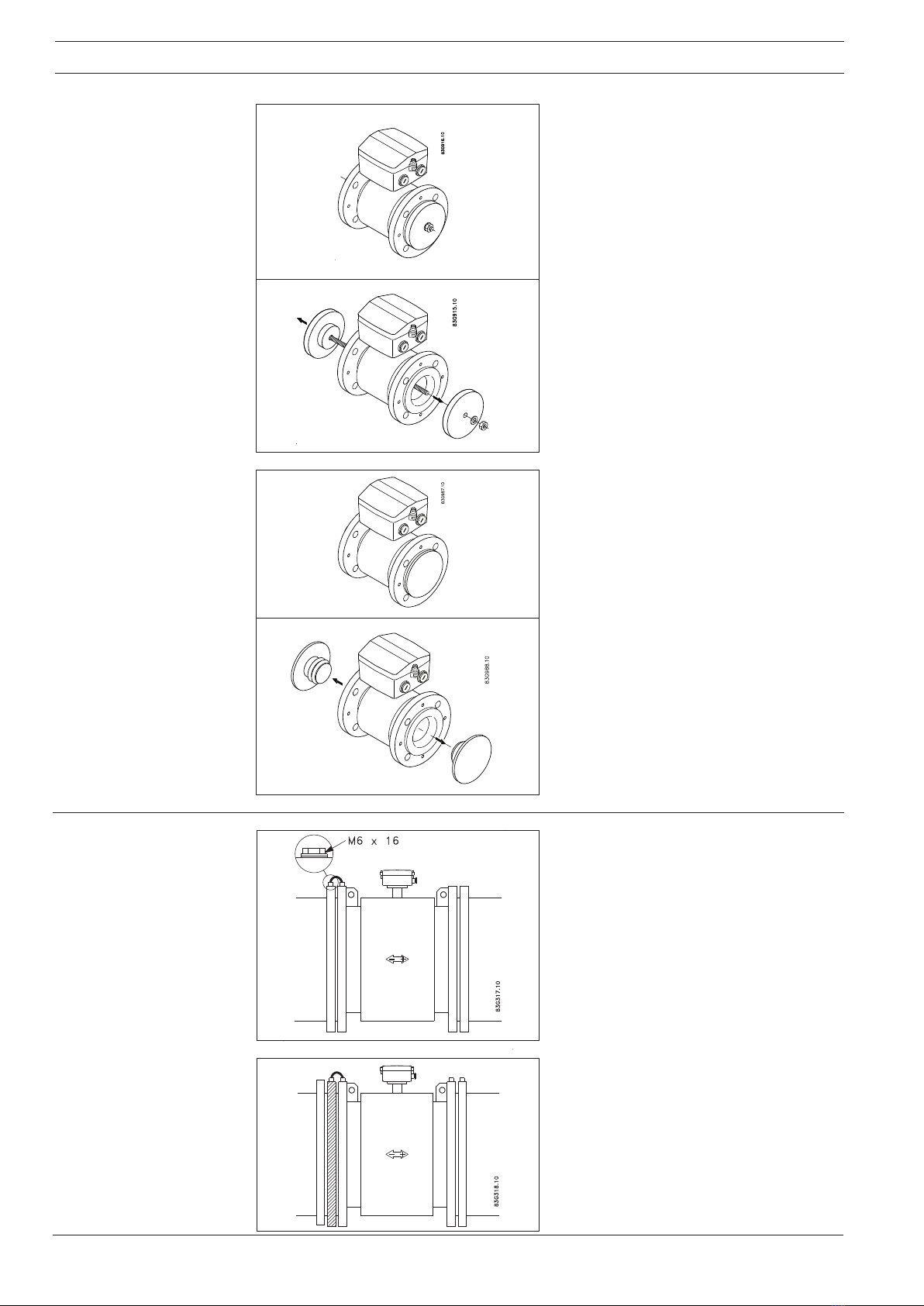
The sensor must be mounted between two
flanges. Gaskets are only necessary when the
flowmeter is installed with earthing flanges as
the liner replaces gaskets.
Installation
Standard bolts must be well lubricated and
tightened evenly around the gasket. Leakage/
damage to the flowmeter or piping may arise if
bolts are overtightened.
Tightening
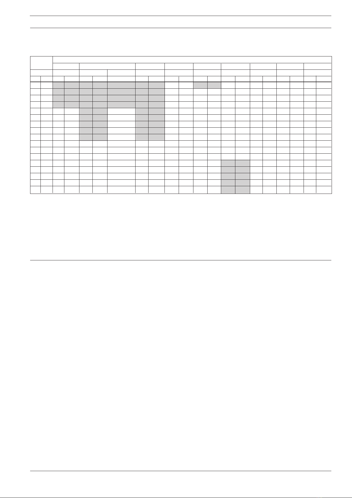
Effect of temperature and
material on working
pressure PN rated flanges
Material Flange Temperature °°
°°
°C
group rating −20 50 100 150 180
1C1 PN 6 6.0 6.0 6.0 5.8 5.6
(A105) PN10 10.0 10.0 10.0 9.7 9.4
PN16 16.0 16.0 16.0 15.6 15.1
PN 25 25.0 25.0 25.0 24.4 23.7
PN 40 40.0 40.0 40.0 39.1 37.9
2C1 PN 6 5.5 5.3 4.5 4.1 3.8
(304) PN 10 9.1 8.8 7.5 6.8 6.3
PN 16 14.7 14.2 12.1 11.0 10.2
PN 25 23.0 22.1 18.9 17.2 16.0
PN 40 36.8 35.4 30.3 27.5 25.5
2C2 PN 6 5.5 5.3 4.6 4.2 3.9
(316) PN 10 9.1 8.9 7.8 7.1 6.6
PN 16 14.7 14.3 12.5 11.4 10.6
PN 25 23.0 22.3 19.5 17.8 16.5
PN 40 36.8 35.6 31.3 28.5 26.4
Metric (Pressures in bar)
PN rated flanges
Material Flange Temperature °°
°°
°F
group rating −5 122 212 302 356
ASTM PN 6 87 87 87 84 81
A105 PN 10 145 145 145 141 136
PN 16 232 232 232 226 219
PN 25 363 363 363 354 344
PN 40 580 580 580 567 550
ASTM PN 6 80 77 65 59 55
A240 PN 10 132 128 109 99 91
304 PN 16 213 206 175 160 148
PN 25 334 320 274 249 232
PN 40 534 513 439 399 370
ASTM PN 6 80 77 67 61 57
A240 PN 10 132 129 113 103 96
316 PN 16 213 207 181 165 154
PN 25 334 323 283 258 239
PN 40 534 516 454 413 383
Imperial (Pressures in Psi)
ANSI flanges
Material Flange Temperature °°
°°
°C
group rating −2 0 38 93 149 180
1.1 Cl. 150 19.7 19.7 17.9 15.9 14.7
(A105) Cl. 300 51.0 51.0 46.6 45.2 44.4
2.1 Cl. 150 19.0 19.0 15.9 14.1 13.6
(F304) Cl. 300 49.7 49.7 41.4 37.2 35.5
2.2 Cl. 150 19.0 19.0 16.2 14.8 14.1
(F316) Cl. 300 49.7 49.7 42.8 38.6 36.9
ANSI flanges
Material Flange Temperature °°
°°
°F
group rating −5 100 200 300 356
ASTM Cl. 150 285 285 260 230 213
A105 Cl. 300 740 740 675 655 644
ASTM Cl. 150 275 275 230 205 197
A240 Cl. 300 720 720 600 540 515
F304
ASTM Cl. 150 275 275 235 215 204
A240 Cl. 300 720 720 620 560 535
F316
The above tables show the effect that an increase of temperature or change of material have
on the maximum working pressure of the flange. The values are independent of nominal size.
For intermediate temperatures use value from nearest higher temperature.
Example
For a PN 16 flange in 2C2 (316) material at 80 degrees the maximum working pressure should
be taken as 12.5 bar.