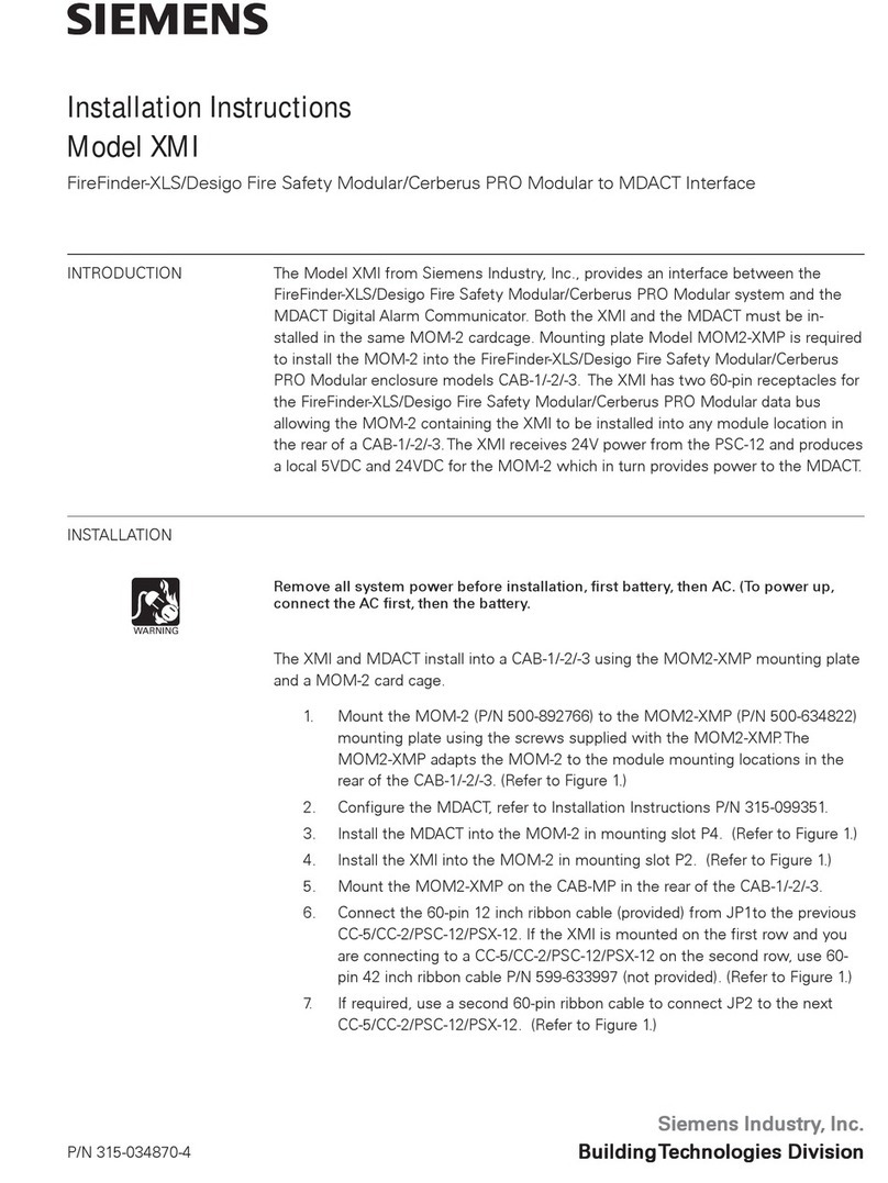
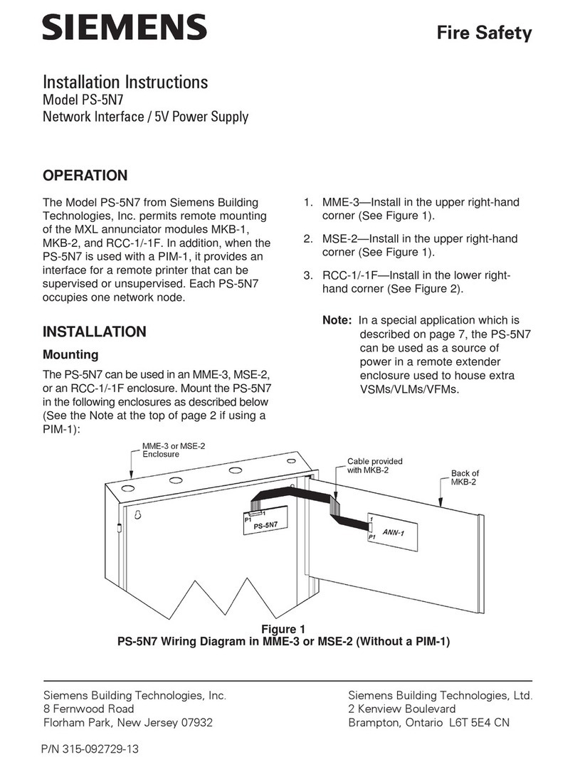
manuals.online logo
Brands
  1. Home
  2. •
  3. Brands
  4. •
  5. Siemens
  6. •
  7. Recording Equipment
  8. •
  9. Siemens SENTRON 7KN POWERCENTER 3000 User manual

Siemens SENTRON 7KN POWERCENTER 3000 User manual

Gerät einbauen
Mounting the device
Gerät anschließen
Connecting the device
1
2
WICHTIG: Beachten Sie alle dem Gerät beiliegenden Dokumente und die Betriebsanleitung, bevor
Sie das Gerät einbauen und anschließen. Die vollständige Dokumentation des Geräts finden Sie im
Internet.
(https://support.industry.siemens.com/cs/ww/de/view/109763838).
IMPORTANT: observe all documents enclosed with the device and the operating instructions manual
before mounting and connecting the device. You find the complete documentation of the device on
the internet.
(https://support.industry.siemens.com/cs/ww/en/view/109763838).
Das Handbuchsymbol weist auf detaillierte Informationen in der Betriebsanleitung hin.
The manual symbol refers to detailed information in the operating instructions.
Stellen Sie sicher, dass die klimatischen Umgebungsbedingungen für die jeweilige Einbaulage
eingehalten werden.
Ensure that the climatic environmental conditions for the specific mounting position are
observed.
Beachten Sie die Position der Feder beim
Anbringen der Hutschienenklammer.
Observe the position of the clip when
attaching the DIN rail clamp.
0.75 ... 2.5 mm2
L+
M
2.5 mm²
T20
M4
T10
T10
T10
T10
Das Gerät darf nur an eine DC 24 V Stromversorgung angeschlossen werden, die den Anforderungen
einer sicheren Kleinspannung (SELV) gemäß der IEC/EN/DIN EN/UL 61010 entspricht.
Im Geltungsbereich UL/CSA 61010-2-201 muss das Gerät beim Betrieb außerhalb eines Gehäuses
nach UL/CSA 61010-2-201 mit NEC Class 2 oder einem energiebegrenztem Stromkreis gemäß
UL/CSA 61010-1 versorgt werden.
The device must only be connected to a 24 VDC power supply which satisfies the requirements of
safety extra low voltage (SELV) according to IEC/EN/DIN EN/UL 61010.
Within the scope of UL / CSA 61010-2-201, the device must be supplied with NEC Class 2 or an
energy-limited circuit according to UL / CSA 61010-1 when operated outside an enclosure according
to UL / CSA 61010-2-201.
Requirements:
• Ensure that the mounting surface on the wall can bear four times the total weight of the
device, including fixing elements.
• Use only the anchors and screws specified in the operating instructions.
• Only use the included screws to fasten the mounting bracket. Longer screws can damage
the inside of the device.
Voraussetzungen:
• Stellen Sie sicher, dass die Anschraubfläche an der Wand das Vierfache des Gesamtgewichts des
Geräts einschließlich Befestigungselemente tragen kann.
• Verwenden Sie nur die in der Betriebsanleitung angegebenen Dübel und Schrauben.
• Verwenden Sie zur Befestigung des Montagewinkels ausschließlich die mitgelieferten
Schrauben. Längere Schrauben können das Geräteinnere beschädigen.
Beachten Sie die Position der Feder beim
Anbringen der Hutschienenklammer.
Observe the position of the clip when
attaching the DIN rail clamp.
Beachten Sie die Orientierung der
Schlüsselloch-Bohrungen beim Anbrin-
gen des Montagewinkels.
Observe the orientation of the keyhole
drill when attaching the mounting bracket.
Stromversorgung anschließen – Connecting the power supply
Schutzleiter anschließen – Connecting the protective earth
Zulässige Einbaulagen – Valid Mounting positions
1.1
1.2
2.2
2.1
Vor Einbau und Inbetriebnahme – Before mounting and commissioning
Gerät anbauen – Mounting the device1.3
Erforderlicher Freiraum um das Gerät
Free space required around the device
1
2
3
0.5 x 2
1
4
Buchmontage
Upright mounting
Basis-Gerät (Schnittstellen vorne / oben / unten)
Base device (Interfaces front)
Hutschienenmontage
Mounting on DIN rails
Wandmontage
Wall mounting
Buchmontage Hutschiene
Upright mounting on DIN rails
Buchmontage
Upright mounting
Wandmontage
Wall mounting
Basis-Gerät (Schnittastellen oben / unten / rechts / links)
Base device (Interfaces top / bottom / right / left)
Buchmontage Hutschiene
Upright mounting on DIN rails
Basis-Gerät (Schnittstellen vorne / oben / unten)
Base device (Interfaces front / top / bottom)
Hutschienenmontage
Mounting on DIN rails
Basis-Gerät (Schnittstellen oben / unten / links / rechts)
Base device (Interfaces top / bottom / left / right)
≥ 50 mm
≥ 50 mm
2
01/2020
L1V30579222002-02
SENTRON
7KN POWERCENTER 3000
Quick Install Guide
Technical Support
http://www.siemens.com/low-
voltage/technical-support
Gerät einbauen
Mounting the device
Gerät anschließen
Connecting the device
Gerät in Betrieb nehmen
Commissioning the device
1
2
3
X1 P1 PN/IE (LAN) X2 P1
3.1 Gerät einschalten – Switching on the device
Gerät in Betrieb nehmen
Commissioning the device
3
Das Gerät startet im Auslieferungszustand automatisch, sobald DC 24 V anliegen.
The device starts automatically as soon as DC 24 V is applied.
1
Haftungsausschluss
Wir haben den Inhalt der Druckschrift auf Übereinstimmung mit der beschriebenen Hard- und
Software geprüft. Dennoch können Abweichungen nicht ausgeschlossen werden, so dass wir für
die vollständige Übereinstimmung keine Gewähr übernehmen. Die Angaben in dieser Druckschrift
werden regelmäßig überprüft, notwendige Korrekturen sind in den nachfolgenden Auflagen
enthalten.
Disclaimer of Liability
We have reviewed the contents of this publication to ensure consistency with the hardware and
software described. Since variance cannot be precluded entirely, we cannot guarantee full
consistency. However, the information in this publication is reviewed regularly and any necessary
corrections are included in subsequent editions.
Siemens AG
Smart Infrastructure
Low Voltage Products
Postfach 10 09 53
93009 REGENSBURG
DEUTSCHLAND
Abbildungen
Das vorliegende Dokument enthält Abbildungen zu den beschriebenen Geräten und Zubehör.
Die Abbildungen können bezogen auf das gelieferte Gerät und Zubehör in Einzelheiten abweichen.
Illustrations
This document contains illustrations of the described devices and accessories.
The illustrations may deviate from the particularities of the delivered device and accessories.
3
Betriebsanzeigen
LED Name Status Beschreibung
PC ON/WD Aus Keine Spannung
Grün BIOS aktiv
Blinkt Grün / Gelb (4 Hz) Hardware-Selbst-Test
Gelb Leerlauf
Blinkt Gelb (4 Hz) Fehlerüberwachung hat ausgelöst
L1 RUN/STOP Aus nicht verwendet
Blinkt Grün (2 Hz) POWERCENTER startet
Grün POWERCENTER aktiv
Gelb nicht verwendet
L2 ERROR Aus nicht verwendet
Rot Schwerwiegender Fehler
Gelb Warnung
L3 MAINT Aus nicht verwendet
Blinkt Gelb (2 Hz) Firmware-Update läuft (nicht ausschalten)
Gelb nicht verwendet
Rot nicht verwendet
L1 RUN/STOP
L2 ERROR Blinkt Gelb (2 Hz) POWERCENTER wird vom Partner angepingt
L3 MAINT
Status Indicators
LED Name Status Description
PC ON/WD OFF No power supply
Green BIOS booting
Flashing Green/Yellow (4 Hz) Power ON self test
Yellow Idle state
Flashing Yellow (4 Hz) Fault monitoring has triggered
L1 RUN/STOP OFF not used
Flashing Green (2 Hz) POWERCENTER started
Green POWERCENTER active
Yellow not used
L2 ERROR OFF not used
Red Fatal error
Yellow Warning
L3 MAINT OFF not used
Flashing Yellow (2 Hz) Firmware update ongoing (don‘t switch OFF)
Yellow not used
Red not used
L1 RUN/STOP
L2 ERROR Flashing Yellow (2 Hz) POWERCENTER is being pinged
L3 MAINT
Erstinbetriebnahme
Zur Erstinbetriebnahme verbinden Sie die aktuellste powerconfig Version oder Web-Interface
über X2 P1. Default IP-Adresse: 192.168.1.2
First setup
For the first setup connect the latest powerconfig version or web-interface via X2 P1. Default IP
address: 192.168.1.2
PC ON/
WD
http://www.siemens.com/lowvoltage/dangerousgood
DE Produkt ist Gefahrgut, Gefahrgutvorschriften beachten!
EN Product is classified as a dangerous good, observe dangerous goods regulations!

Other manuals for SENTRON 7KN POWERCENTER 3000

3

Other Siemens Recording Equipment manuals

Siemens IAQ6-1 User manual

Siemens

Siemens IAQ6-1 User manual

Siemens SIMATIC NET CP 5613 User manual

Siemens

Siemens SIMATIC NET CP 5613 User manual

Siemens SIMATIC NET DP/AS-i Link 20E User manual

Siemens

Siemens SIMATIC NET DP/AS-i Link 20E User manual

Siemens PMI User manual

Siemens

Siemens PMI User manual

Siemens RNI User manual

Siemens

Siemens RNI User manual

Siemens SIPLUS CMS4000 ION BINARYINPUT T001 User manual

Siemens

Siemens SIPLUS CMS4000 ION BINARYINPUT T001 User manual

Siemens SIMATIC HMI KP400 Comfort User manual

Siemens

Siemens SIMATIC HMI KP400 Comfort User manual

Siemens N148/23 User manual

Siemens

Siemens N148/23 User manual

Siemens simatic ET 200MP User manual

Siemens

Siemens simatic ET 200MP User manual

Siemens N148/22 Service manual

Siemens

Siemens N148/22 Service manual

Siemens SITOP PSU6200 Instructions for use

Siemens

Siemens SITOP PSU6200 Instructions for use

Siemens SIPROTEC 7XV5662-0AC03 User manual

Siemens

Siemens SIPROTEC 7XV5662-0AC03 User manual

Siemens AS-i Master CM 1243-2 a User manual

Siemens

Siemens AS-i Master CM 1243-2 a User manual

Siemens SIMATIC HMI KTP700F Mobile User manual

Siemens

Siemens SIMATIC HMI KTP700F Mobile User manual

Siemens SINAMICS V90 User manual

Siemens

Siemens SINAMICS V90 User manual

Siemens NIC-C User manual

Siemens

Siemens NIC-C User manual

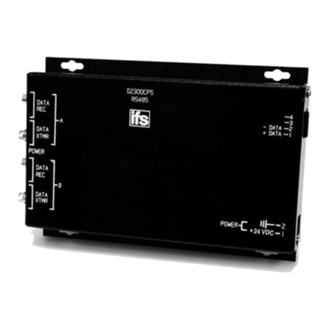
Siemens D2300CPS User manual

Siemens

Siemens D2300CPS User manual

Siemens CIM User manual

Siemens

Siemens CIM User manual

Siemens VIU-20 User manual

Siemens

Siemens VIU-20 User manual

Siemens VDO DTCO 1381 Parts list manual

Siemens

Siemens VDO DTCO 1381 Parts list manual

Siemens CERBETUS PYROTRONICS VDT Specification sheet

Siemens

Siemens CERBETUS PYROTRONICS VDT Specification sheet

Siemens SIMATIC ET 200SP User manual

Siemens

Siemens SIMATIC ET 200SP User manual

Siemens SIMATIC Distributed I/O System DP/ASi Link User manual

Siemens

Siemens SIMATIC Distributed I/O System DP/ASi Link User manual

Siemens SINAMICS S120 Installation and operation manual

Siemens

Siemens SINAMICS S120 Installation and operation manual

Popular Recording Equipment manuals by other brands

MIDIbox SpeakJet K64 Modul manual

MIDIbox

MIDIbox SpeakJet K64 Modul manual

Flightcell VAM Installation and configuration manual

Flightcell

Flightcell VAM Installation and configuration manual

Midian Electronics TTE-7 quick guide

Midian Electronics

Midian Electronics TTE-7 quick guide

Alesis iO14 Quick start owner's manual

Alesis

Alesis iO14 Quick start owner's manual

Roland TR-08 user guide

Roland

Roland TR-08 user guide

Vesta Fire MR-30 owner's manual

Vesta Fire

Vesta Fire MR-30 owner's manual

Brady ProImage Plus3000 PosterPrinter Helpful operation tips

Brady

Brady ProImage Plus3000 PosterPrinter Helpful operation tips

Briteq VP-P37.5 Preliminary Setup Instructions

Briteq

Briteq VP-P37.5 Preliminary Setup Instructions

Cochlear Baha 5 SuperPower user manual

Cochlear

Cochlear Baha 5 SuperPower user manual

EMT PSP 244 Operation manual

EMT

EMT PSP 244 Operation manual

Behringer ULTRAFLEX PRO EX3200 user manual

Behringer

Behringer ULTRAFLEX PRO EX3200 user manual

XFIRE AUDIO XFR Series quick guide

XFIRE AUDIO

XFIRE AUDIO XFR Series quick guide

IK Multimedia iRig Keys 37 user manual

IK Multimedia

IK Multimedia iRig Keys 37 user manual

Patching Panda PARTICLES user manual

Patching Panda

Patching Panda PARTICLES user manual

GMTCNT GOP52-150AT Installation instruction

GMTCNT

GMTCNT GOP52-150AT Installation instruction

Superscope PSD330 owner's manual

Superscope

Superscope PSD330 owner's manual

Phonic FIREFLY 302 USB user manual

Phonic

Phonic FIREFLY 302 USB user manual

Pfeiffer Vacuum ASI 35 operating instructions

Pfeiffer Vacuum

Pfeiffer Vacuum ASI 35 operating instructions

manuals.online logo
manuals.online logoBrands
  • About & Mission
  • Contact us
  • Privacy Policy
  • Terms and Conditions

Copyright 2025 Manuals.Online. All Rights Reserved.