manuals.online logo
Brands
  1. Home
  2. •
  3. Brands
  4. •
  5. Siemens
  6. •
  7. Security Sensor
  8. •
  9. Siemens FDO421 User manual

Siemens FDO421 User manual

A6V10323926_d_en_-- SIEMENS Industry, Inc.
2022-07-11 Smart Infrastructure
Installation Instructions
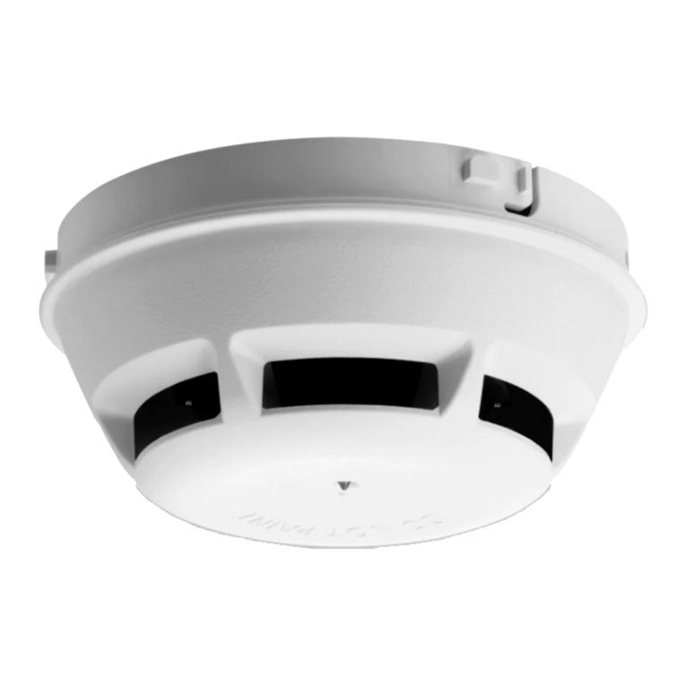
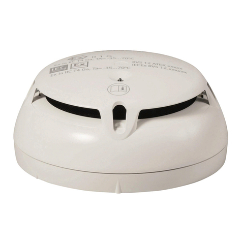
Model FDO421
Photoelectric Detector
UL268 7th edition listed
Scan for electronic version
Figure 1
These instructions are written in accordance with the
installation guidelines of NFPA 72,
National Fire Alarm
Code, and CAN/ULC-
S524, The Installation of Fire Alarm
Systems.
Do not locate the detectors next to an oil burner, or
garage where exhaust fumes can trigger an alarm. Other
causes of false alarms are dust accumulation, heavy
concentrations of steam, heavy pipe or cigar smoke, and
certain aerosol sprays.
CAUTION
DO NOT install this detection device until all construction
is completed.
DO NOT store this detection device where it can be
contaminated by dirt, dust, or humidity.
AIR
CURRENTS
Before a detector can sense a fire, the products of
combustion or smoke must travel from the fire to the
detector. This travel is especially influenced by air
currents; therefore, consider air movement when
designing the system. Whi
le combustion products tend
to rise, drafts from hallways, air diffusers, fans, etc., may
help or hinder the travel of combustion products to the
detector. When positioning a detector at a particular
location, give consideration to windows and doors, both
open and closed, to ventilating systems, both in and out
of operation, and to other factors influencing air
movement. Do not install a detector in the air stream of
a room air supply diffuser. It is better to position a
detector closer to an air return.
Th
e distance that products of combustion or smoke
travel from a fire to the detector is not usually the shortest
linear route. Combustion products or smoke usually rise
to the ceiling, then spread out. Average ceiling heights of
8 to 10 feet do not abnormall
y affect detector response.
High ceilings, located in churches, warehouses,
auditoriums, etc., do affect detector response and should
be considered.
SPECIAL CEILING CONSTRUCTION FACTORS
Ceiling obstructions change the natural movement of air
and
combustion products. Depending on the direction of
smoke travel, joists and beams can slow the movement
of heated air and smoke, while pockets between them
can contain a reduced level of smoke. Take obstructions
created by girders, joists, beams, air condi
tioning ducts,
or architectural design into consideration when
determining area protection. Refer to the Initiating
Devices chapter of NFPA Standard 72 for Location and
Spacing requirements for specific types of construction;
e.g. beam, suspended, level, s
loped and peaked
ceilings. The detector is also compatible with the
following mechanical protection guard model: STI-
9604
(see www.STI-USA.com for details).
DETECTOR PLACEMENT
Although no specific spacings are set for the detectors
used for a clean air application, use 30-foot
center
spacing (900 sq ft) from NFPA Standard 72 initiating
devices chapter and CAN/ULC-
S524, if practical, as a
guide or starting point for a detector installation layout.
This spacing, however, is based on ideal conditions
–
smooth ceiling, no air movement, and no physical
obstructions. In some applications, therefore,
considerably less area is protected adequately by each
smoke detector. This is why it is mandatory to closely
follow the installation drawings. In all installat
ions place
the detector on the ceiling, a minimum of 6 inches from
a side wall, or on a wall, 12 inches from the ceiling.
For an ideal, smooth ceiling condition, place the
detectors at a maximum center spacing of 50 feet (2500
square feet). Drawings provided or approved by
Siemens Industry, Inc., or by its authorized distributors
are extremely important.The detector placements
shown on these drawings were chosen after a careful
evaluation of the area that is protected. Such factors as
air currents, temperature, humidity, pressure, and the
nature of the fire load were carefully considered.
Especially noted were the room or area configuration
and the type of ceiling (sloped or flat, smooth or
beamed). Siemens Industry, Inc.’s extensive experience
in the design of the system assures the best detector
placement by following these drawings. Sound
engineering judgment by qualified personnel must be
followed.
TO AVOID NUISANCE ALARMS
Do not locate the detectors where excessive smoke
concentrations exist under norma
l conditions, or in areas
of prolonged high relative humidity where condensation
occurs.
2 A6V10323926_d_en_--
TEMPERATURE – HUMIDITY – PRESSURE - AIR
VELOCITY
The temperature range for the FDO421 detector is 32
°F
(0 °C) to 100 °F (38
°C). Use the detector in
environments where the humidity does not exceed 95%
(non-
condensing). Normal changes of atmospheric
pressure do not affect detector sensitivity. The air
velocity range is 0-
300 ft/min for open areas applications
and 0-4000 ft/min for direct in air duct
applications.
Follow detector spacing and location requirements in
NFPA 72 Chapter for High Air Movement Areas and
Control of Smoke Spread.
LED INDICATOR OPERATION
The Model FDO421
contains an LED indicator capable
of flashing either one of three distinct colors: green,
yellow, or red. The microprocessor-
based detector
monitors the following:
Smoke in its sensing chamber

Smoke sensitivity is within the range indicated on the
nameplate label
Internal sensors and electronics
Based on the results of the monitoring, the LED indicator
flashes the following:
F
l
a
sh
C
o
l
o
r
Cond
iti
on
Flash I
n
t
e
r
v
a
l
(
S
e
conds
)
Green *
Normal supervisory operation.
S
moke
sensit ivity is wit hin rated
limits.
10
Yellow Detector is in trouble and
needs
replacemen
t.
4
Red
A
larm 1
No
Flashes
Detector is not powered,
or
replacement is
needed
.
–
* LED can be turned off. Please follow the corresponding
description
o
f the Panel
used
.
DETECTOR PROGRAMMING
Each detector must be programmed to respond to a
n
address between 001 - 252.
To program the detector address, use the Model DPU
Device Programming Unit. Refer to the DPU Manual, P/N
315-033260.
Record the loop and device number (system
address) for
the detector on the detector label and on the base to
prevent installing the detector in the wrong base. The
optional DPU label printer can be used for this purpose.
Each detector provides pre-
programmed parameter sets
which can be selected by
the panel. Follow the
corresponding description of the panel used.
Standard:
To be used for open area protection
applications. The sensitivity is 3.765 ±0.235
%/FT.
Note: Above value for the sensitivity is evaluated
using t
he UL smoke box. The same detector has a
sensitivity of 1.415 ±0.195
%/FT when evaluated
using the ULC smoke box. The ULC smoke box
operates with a faster increase of the smoke density.
Duct:
To be used in direct in air duct applications.
The sensitivity is 1.815 ±0.145 %/FT.
WIRING
The FDO421
supports two operation modes: polarity
insensitive mode and isolator mode. The Detector can be
wired for either mode (refer to Figure 2 and 3). During
the isolator mode, the built-
in dual isolators will work at
both sides of the Detector to isolate the li
ne short in front
or behind the device.
When the FDO421
is wired in polarity insensitive mode,
Line -6 and -5 can be either line of the loop.
When the FDO421 is wired for I
solator mode, the positive
line needs to be connected to 1b and the negative line to
6. The next device needs to be connected to 1b and 5.
The Line Isolator is located between connector 6 and 5.
NOTICE
Ensure that the panel supports Isolator
mode for
the FDO421 product version 17.
Isolator mode must not be used with a FDO421
product version <17. You will find the product
version number on the detector label.
DETECTOR MOUNTING
To ensure proper installation of the detector head into the
base, be sure the wires are properly dressed at
installation:
Position all wires flat against the base.
Take up all slack in the outlet box
Route wires away from connector terminals.
TO INSTALL DETECTOR HEAD

Rotate detector counterclockwise while gently
pressing on it until the detector seats fully into base.

Then rotate the detector clockwise until it stops and
locks in place. Insert optional locking screw (Order
Model LK-11).
TO REMOVE DETECTOR HEAD:

Loosen locking screw, if installed. Then rotate the
detector counterclockwise until stop is reached.
Pull detector out of base.
DETECTOR TESTING
Only qualified service personnel should test. To assure
proper operation of the detector, both the Sensitivity and
Functional Test should be conducted. The minimum test
schedule may be found in the current edition of NFPA
72.
SENSITIVITY MEASUREMENT
The sensitivity of FDO421
detectors can be tested
individually using the DPU. Refer to the DPU Manual,
P/N 315-
033260. The sensitivity can be measured by the
panel. Follow the instructions of the panel used.
FDO421
S54320-F4-A1
17
A6V10323926_d_en_-- 3
FUNCTIONAL TEST
Perform a functional (Go, No-
Go) test by activating the
detector using the following test gases:
Smoke Sabre, P/N SMOKESABRE-01-001
Smoke Centurion (M8), P/N M8-001-024
Solo A5 Smoke Detector Tester Gas
P/N SOLOA5 001
Solo A10, P/N SOLO A10 / A10s
Testifire 1001 / 2001, P/N TS3-001
HSI PurCheck, P/N HO-30S
HSI SmokeCheck™, P/N HO-25S
Follow the instruction on the gas canister label. This test
is simply used to ensure that smoke can enter the
sensing chamber and alarm the control
panel when the
detector reaches the programmed obscuration
(concentration) level.
The FDO421
detectors can also be tested individually
using the DPU.
Refer to the DPU Manual, P/N 315-033260.
MAINTENANCE
The control unit automatically indicates the trouble
message for the FDO421
detector whose smoke
chamber changes to the level where the set sensitivity
cannot be maintained. In such circumstances, the
detector may require replacement.
CAUTION
Under no circ
umstances is the detector head to be
disassembled.
No repairs should be attempted.
DO NOT PAINT
The detector is marked DO NOT PAINT. This is intended
to prohibit painting during routine maintenance of the
occupancy which can affect proper operation of the
detector.
Polarity insensitive wiring:
Figure 2
Isolator mode
wiring:
Figure 3
Wire size: maximum 14 AWG, minimum 18 AWG (Wire larger than 14 AWG can damage the
connector)
TO INITIATING CIRCUIT
OF SIEMENS COMPATIBLE
CONTROL UNIT
OPTIONAL
REMOTE
ALARM
INDICATOR
MODELS
8727W / 8727C /
RL-HW / RL-HC
TO NEXT BASE
TO NEXT BASE
DO NOT USE AN
END OF LINE DEVICE
DETECTOR BASE
MODEL DB-11/DB-11E
LINE 1 *
LINE 2 *
5
6
1a
TB1
TB3
TB2
1b
5
6
1a
1b
** The relay contacts are shown after System reset, which represents the non-alarm condition.
* FDO421 is a polarity insensitive detector. Line 1 and Line 2 can be either line of the loop.
5+
NO
C
NC
6-
RELAY CONTACTS **
3A, 120 VAC
3A, 30 VDC
DO NOT USE AN
END OF LINE DEVICE
OPTIONAL
REMOTE
ALARM
INDICATOR
MODELS
8727W / 8727C /
RL-HW / RL-HC
TO NEXT BASE
TO NEXT BASE
DO NOT USE AN
END OF LINE DEVICE
DETECTOR BASE
MODEL DB-11/DB-11E
LINE 1
LINE 2
5
6
1a
TB1
TB3
TB2
1b
5
6
1a
1b
*
The relay contacts are shown after System reset, which represents the non-alarm condition.
5+
NO
C
NC
6-
RELAY *
CONTACTS
3A, 120 VAC
3A, 30 VDC
DO NOT
USE AN
END OF LINE DEVICE
++
–
–
To initiating circuit of
SIEMENS compatible control unit
Siemens Industry, Inc.
Smart Infrastructure
8, Fernwood Road
Florham Park, New Jersey 07932
www.siemens.com/buildingtechnologies
Siemens Canada Limited
Smart Infrastructure
2 Kenview Boulevard
Brampton, Ontario L6T 5E4
Canada
© Siemens Industry, Inc.
Data and design subject to change without notice.
A6V10323926_d_en_-- P/N A5Q00041068
In the device line, up to 30 of any compatible devices in
polarity insensitive mode with 20 ohms max line
resistance can be isolated between two
modules in
isolator mode in a Class A Style 6 wiring.
In the device line, up to 30 of any compatible devices in
polarity insensitive mode with 20 ohms max line
resistance can be isolated behind one module in isolator
mode in a Class B Style 4 wiring.
HLIM isolator module and SBGA-
34 sounder base
cannot be used in the same loop with the modules in
isolator mode.
FCC Statement
WARNING!
Installation and usage of equipment not in accordance with instructions manual may
result in:
Radiation of radio frequency energy
Interference to radio communications
Install and use equipment in accordance with installation instructions manual
Read the following information
This equipment generates, uses, and can radiate radio frequency energy and if not installed and used in
accordance with the instructions manual, may cause interference to radio communications.
It has been tested and found to comply with the limits for a Class A computing device pursuant to Part 15 of FCC
Rules, which are designed to provide reasonable protection against such interference when operated in a
commercial environment.
Operation of this equipment in a residential area is likely to cause interference in which case the user at his own
expense will be required to take whatever measures may be required to correct the interference.

Other manuals for FDO421

2

This manual suits for next models

1

Other Siemens Security Sensor manuals

Siemens 5SV60 MC Series User manual

Siemens

Siemens 5SV60 MC Series User manual

Siemens SITRANS F FUH1010 Series User manual

Siemens

Siemens SITRANS F FUH1010 Series User manual

Siemens OOH740 User manual

Siemens

Siemens OOH740 User manual

Siemens Cerberus CS1140 Guide

Siemens

Siemens Cerberus CS1140 Guide

Siemens FDOOT271 Guide

Siemens

Siemens FDOOT271 Guide

Siemens 5TC1585 User manual

Siemens

Siemens 5TC1585 User manual

Siemens milltronics User manual

Siemens

Siemens milltronics User manual

Siemens FDOOT271-O Guide

Siemens

Siemens FDOOT271-O Guide

Siemens OH720 User manual

Siemens

Siemens OH720 User manual

Siemens OOH740-A9-Ex User manual

Siemens

Siemens OOH740-A9-Ex User manual

Siemens ANT 3 Administrator guide

Siemens

Siemens ANT 3 Administrator guide

Siemens RAR Series User manual

Siemens

Siemens RAR Series User manual

Siemens FDT181 User manual

Siemens

Siemens FDT181 User manual

Siemens 5WG1 258-2EB22 User manual

Siemens

Siemens 5WG1 258-2EB22 User manual

Siemens SINUMERIK 840D sl TCU 30.3 User manual

Siemens

Siemens SINUMERIK 840D sl TCU 30.3 User manual

Siemens FDO421 User manual

Siemens

Siemens FDO421 User manual

Siemens MSI-51B Technical specifications

Siemens

Siemens MSI-51B Technical specifications

Siemens FDO421 User manual

Siemens

Siemens FDO421 User manual

Siemens DF11 Series User manual

Siemens

Siemens DF11 Series User manual

Siemens 5SM6 01 2 Series User manual

Siemens

Siemens 5SM6 01 2 Series User manual

Siemens QRB Series User manual

Siemens

Siemens QRB Series User manual

Siemens AlgoRex CS1140 Operating instructions

Siemens

Siemens AlgoRex CS1140 Operating instructions

Siemens LAE10 User manual

Siemens

Siemens LAE10 User manual

Siemens DBS721 User manual

Siemens

Siemens DBS721 User manual

Popular Security Sensor manuals by other brands

Powerfix Profi KHH 2927-2 operating instructions

Powerfix Profi

Powerfix Profi KHH 2927-2 operating instructions

GJD D-Tect 1 manual

GJD

GJD D-Tect 1 manual

Me MERCURY D-47 user manual

Me

Me MERCURY D-47 user manual

Thorne & Derrick ToxiRAE 3 user guide

Thorne & Derrick

Thorne & Derrick ToxiRAE 3 user guide

Clas Ohlson ZP3102EU manual

Clas Ohlson

Clas Ohlson ZP3102EU manual

Watts FloodSafe WDS-PV manual

Watts

Watts FloodSafe WDS-PV manual

hager TRC301B quick start guide

hager

hager TRC301B quick start guide

SECO-LARM ENFORCER E-964-Q660Q manual

SECO-LARM

SECO-LARM ENFORCER E-964-Q660Q manual

Optex Fit Series installation instructions

Optex

Optex Fit Series installation instructions

Mule Lighting , Inc. CEL Installation and operation instructions for

Mule Lighting , Inc.

Mule Lighting , Inc. CEL Installation and operation instructions for

Collingwood Lighting HBPIR installation instructions

Collingwood Lighting

Collingwood Lighting HBPIR installation instructions

Keysight 8473B Operating and service guide

Keysight

Keysight 8473B Operating and service guide

Hytronik HIM31 manual

Hytronik

Hytronik HIM31 manual

Crestron PinPoint PP-100 installation guide

Crestron

Crestron PinPoint PP-100 installation guide

ESYLUX DEFENSOR MD 200 24 IR 1C IP55 WH operating instructions

ESYLUX

ESYLUX DEFENSOR MD 200 24 IR 1C IP55 WH operating instructions

STEINEL L830LED iHF Cubo instructions

STEINEL

STEINEL L830LED iHF Cubo instructions

BeaconMedaes DiamondCare installation instructions

BeaconMedaes

BeaconMedaes DiamondCare installation instructions

RAPITEST WPS 115 manual

RAPITEST

RAPITEST WPS 115 manual

manuals.online logo
manuals.online logoBrands
  • About & Mission
  • Contact us
  • Privacy Policy
  • Terms and Conditions

Copyright 2025 Manuals.Online. All Rights Reserved.