HARDWARE INSTALLATION
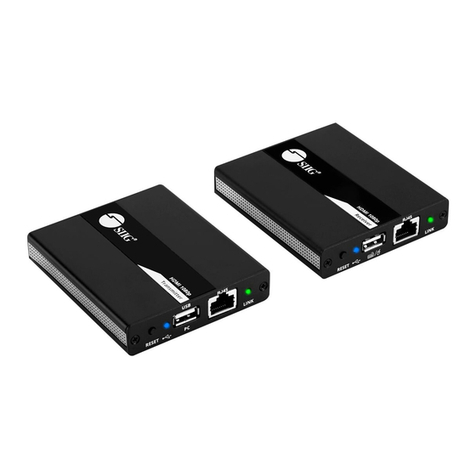
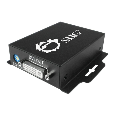
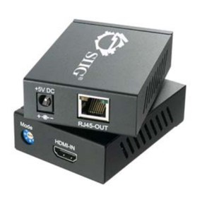
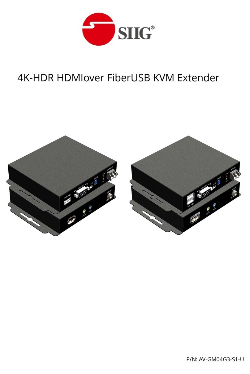
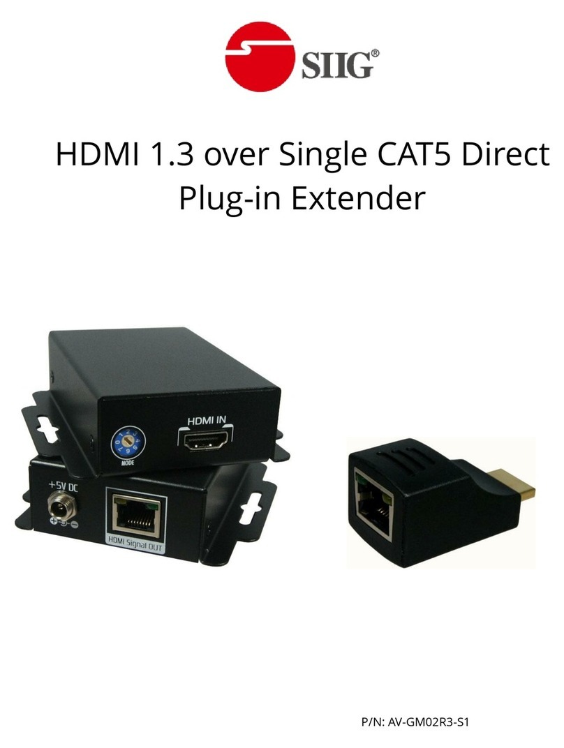
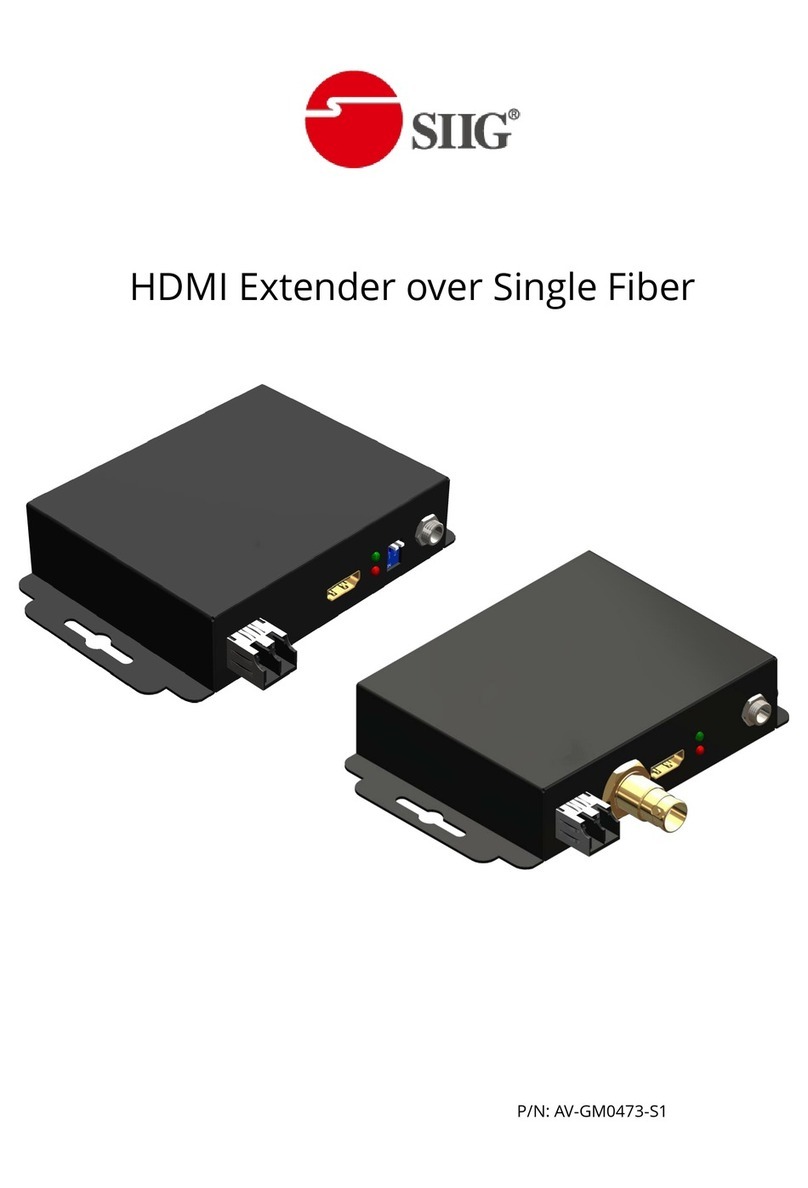
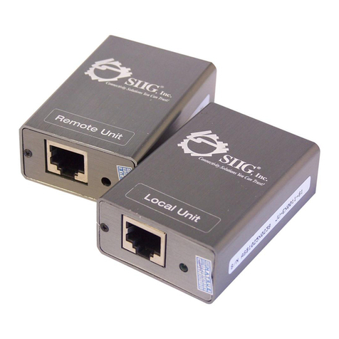
1. Connect a HDMI or DVI source (e.g., a Blu-ray Disc player) to the Transmitting Module.
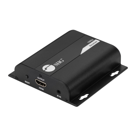
2. Connect a HDMI or DVI display (e.g., a HDTV) to the Receiving Module.
3. Connect two solid Cat-5/5e/6 UTP/STP cable between the Transmitting and Receiving Modules.
4. Make sure these two solid Cat-5/5e/6 UTP/STP cable are tightly connected and not loose.
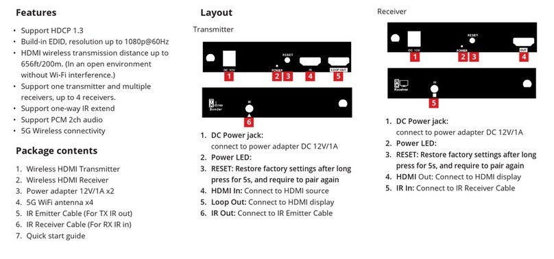
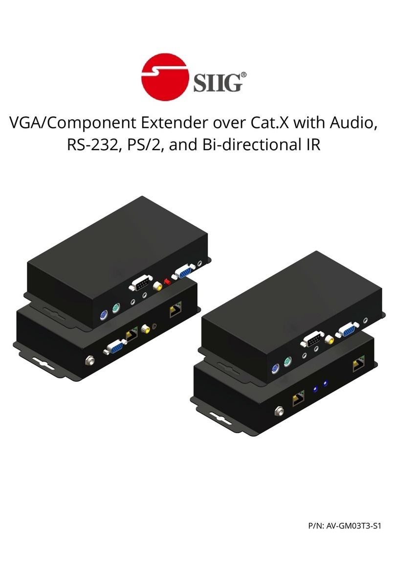
5. If you want to control the source devices at display side, plug in the IR blaster to the
Transmitting Module and the IR receiver to the Receiving Unit. If you want to control the display
at source side, plug in the IR receiver to the Transmitting Module and the IR blaster to the
Receiving Module.
6. Plug in the 5V DC power supply unit to the latch-locking power jack on either the Transmitting
Unit or the Receiving Unit.
7. If you see flickering or blinking image on the display, adjust the rotary control switch to improve
the cable skew. MAX stands for the strongest HDMI signal level for longest possible transmission
length while MIN stands for the weakest HDMI signal level for short transmission length. Try
adjusting the signal level from MIN to MAX to find the optimal setting for the HDMI over CAT5
transmission.
NOTICE
1. When adjusting the signal level on the Receiving unit, please dial the rotary control switch from
MIN to MAX and stop turning the rotary switch whenever the audio/video is playing normally.
Inappropriate signal level setting may cause overpowering issue that would shorten the product
life significantly!
2. Wrongly insert IR blaster and IR receiver to wrong 3.5mm infrared sockets may result in the
failure of the IR extenders. Please check carefully before plugging in the IR extender to the
respective IR sockets.
3. If the DVI or HDMI device requires the EDID information, please use EDID Reader/Writer to
retrieve and provide DVI or HDMI display EDID information.
4. All HDMI over CAT5 transmission distances are measured using Belden 1583A CAT5e 125MHz
UTP cable and ASTRODESIGN Video Signal Generator VG-859C & VG-870B.
5. The transmission length is largely affected by the type of Cat-5/5e/6 cables, the type of HDMI
sources, and the type of HDMI display. The testing result shows solid UTP cables (usually in the
form of 300m [1,000ft] bulk cables) can transmit a lot longer signals than stranded UTP cables
(usually in the form of fixed length patch cords). Shielded STP cables are better suited than
unshielded UTP cables. A solid UTP Cat-5e cable shows longer transmission range than stranded
STP Cat-6 cable. For long extension applications, solid UTP/STP cables are the only viable choice.
6. EIA/TIA-568-B termination (T568B) for Cat-5/5e/6 cables is recommended for better
performance.
7. To reduce the interference among the unshielded twisted pairs of wires in Cat-5/5e/6 cable, one
can use shielded STP cables to improve EMI problems, which is worsen in long transmission.
8. Because the quality of the CAT5/6 cables has the major effect on how long the transmission limit
can achieve and how good is the received picture quality, the actual transmission range is
subject to one's choice of Cat-5/5e/6 cables. For desired resolutions greater than 1080i or
1280x1024, a Cat-6 cable is recommended.
9. If your HDMI display has multiple HDMI inputs, it is found that the first HDMI input [HDMI input
